US998396A - Climbing and scaling device. - Google Patents
Climbing and scaling device. Download PDFInfo
- Publication number
- US998396A US998396A US59413510A US1910594135A US998396A US 998396 A US998396 A US 998396A US 59413510 A US59413510 A US 59413510A US 1910594135 A US1910594135 A US 1910594135A US 998396 A US998396 A US 998396A
- Authority
- US
- United States
- Prior art keywords
- hoops
- pole
- hoop
- climbing
- members
- Prior art date
- Legal status (The legal status is an assumption and is not a legal conclusion. Google has not performed a legal analysis and makes no representation as to the accuracy of the status listed.)
- Expired - Lifetime
Links
Images
Classifications
-
- A—HUMAN NECESSITIES
- A63—SPORTS; GAMES; AMUSEMENTS
- A63B—APPARATUS FOR PHYSICAL TRAINING, GYMNASTICS, SWIMMING, CLIMBING, OR FENCING; BALL GAMES; TRAINING EQUIPMENT
- A63B27/00—Apparatus for climbing poles, trees, or the like
- A63B27/02—Climbing devices for round poles or trees attachable to the feet
Definitions
- the device is useful not only with wooden poles, but with poles of concrete or other materials.
- Figure 1 is a view showing a complete de vice
- Figs. 2 and 8 are views showing a modified connection for the parts of the device, Fig. 2 being a face view, and Fig. 3, a section thereof
- Fig. 4 is a detail View of a clip used in the construction shown in Fig. 1
- Figs. 5, 6, 7, 8 and 9 are detail views showing modifications of the device illustrated in Fig. 1.
- a, a are two hoops of springy steel of any suitable kind, preferably hard silver hoop steel such as is used for saws.
- the ends of the strip of material forming each hoop are connected to gether by a suitable device allowing them to be disconnected when required.
- a metal piece Z) with its edges turned over as shown is riveted to one end of the strip a, and the other end is passed beneath the turned over edges of the piece 6 and is held in place by a bent metal holder 0 which is inserted through a hole in the end carrying the piece I) and in one of a series of holes in the other end of the strip.
- the holder 0 is so made as shown that it can be applied only in one position and when turned from that position will fill the two registering holes and will so prevent the ends of the strip from separating.
- the turned over edges 6 will prevent the ends from opening out so that they can only be separated by sliding longitudinally one upon the other. Slots are formed at d in each of the strips, and pins 6 with their ends riveted over or with washers upon them as shown are passed through the slots (Z to act as pivots connecting the one Specification of Letters Patent.
- f, f are metal stir rups each attached to one of the hoops a at a suitable point as forinstance by a bolt g, the hoop being preferably strengthened by an inserted metal piece it at the point of attachment of the stirrup.
- the edges of the hoops a may be roughened or notched in any suitable way to cause them to grip the pole, as indicated in Figs. 8 and 9 for example, wherein portions of both an upper and a lower curve of the hoops a are shown, with inwardly turned teeth y at their gripping edges; or pieces of hemp rope 70 or the like may be inserted in the hoops to form the gripping surfaces, as indicated in Fig. 1.
- the pieces of rope 70 may be held in place by wires Z having their ends passed through holes in the hoops and twisted as shown to prevent them from being drawn through the holes, or any other suitable device may be used for binding the ropes 7c in place: At the ends where the ropes pass the attachment devices 6, c, the said ropes must be detachably held in place and for this purpose spring clips we may be provided formed for instance as indicated in the detail view, Fig. 4, with a loop to fit around the rope and with bent tongues to engage, over the edges of the hoop.
- a rope may be used which is wrapped around the hoop a as indicated in the detail view, Fig. 5; or the gripping surface may be formed in any other suitable way as for instance by riveting a stout leather or indiarubber strip 1) in the hoop.
- any other suitable form of removable connection may be used.
- Figs. 2 and 3 show a modified construction.
- one end of the hoop a has a metal piece or bridge a riveted around or otherwise attached to it, into which the other end of the hoop a, having a number of holes therein as shown, is inserted.
- the end carrying the bridge piece a has a spring tongue 0 riveted at g thereon, with a stud or pin 79 on its free end adapted to pass through registering holes in the two ends of the hoop a and through a hole'in the bridge piece 72.
- a slide 1" working in guides s and with a slot 25 in it to permit the passage of the head of the stud p, and to lock the latter as illustrated.
- a depression at u in the slide 1" engaging in a corresponding depression in the bridge piece n, will insure that the slide remains in the locking position unless forced away from the same.
- the pivots 6, instead of being formed as shown in Fig. 1, may for instance be formed by brass or other rivets or rollers m, as indicated in Fig. 7, passing through the slots at (Z in the hoops a and connecting the hoops together while forming pivots for the same.
- the device above described is used as follows :VVhen a pole is to be sealed with the device, the connections at Z) of the ends of the hoops are opened, allowing the device to be applied to the pole at the base thereof, and then the connections are remade so as to close the hoops around the pole in approximately the position shown in Fig. 1 with the stirrups f at the bottom of each side.
- the dotted lines marked w in Fig. 1 represent a pole of small diameter to which the device is applied.
- the hoops a For a pole of smaller size the hoops a would be reduced in size by connecting them together by the device 0 or otherwise at holes farther from the end of the strip, and where taper poles are used the diameters of the hoops will be set at the bottom of the pole to be only slightly larger than the diameter of the pole to be scaled;
- each of the hoops besides having the action above referred to in permitting the hoops to grip the pole independently of one another, also allow for the changes in the size of the hoops for different sizes of poles, and permit the stirrups f to be fixed on the hoops, these latter being turned to bring the stirrups to the mid-position between the pivot points when the sizes of the hoops are changed by means of the connections 7), c, or their equivalent.
- the device is to be used on poles of a standard size only it need not necessarily be provided with an adjustable connection for each of the hoops, but the ends of the hoops may be arranged to be always connected together in one and the same position as will be obvious.
- I declare that what I claim is 1.
- a gripping device for use in climbing poles, the combination of a pair of intersecting hoops, and means for pivotally connecting said hoops at their points of intersection, each hoop being flexible in a plane passing through the pivots, and substantially rigid in a plane perpendicular to the first plane; with attachments on the two members adapted to take the weight of the climber applied by the hands or feet to the said attachments.
- a gripping device for use in climbing poles, the combination of a pair of curved members flexible in one plane and substantially rigid in a plane at right-angles thereto, and means for connecting the ends of said curved members upon themselves to form closed hoops which are flexible in the plane of the circumference, but are substantially rigid in a plane at right-angles thereto; with means for pivotally connecting said members together, and attachments on the two members adapted to take the weight of the climber applied by the hands or feet to the said attachments.
- a gripping device for use in climbing poles, the combination of apair of flexible curved members with means for connecting the ends of said members upon themselves to form closed hoops of various sizes, slots in the said members and rivets passed through corresponding slots adapted to connect the two members pivotally together while permitting a certain amount of relative movement across the pivots, and attachments on the two members adapted to take the weight of the climber applied by the hands or feet to the said attachments.
- a gripping device for use in climbing poles, the combination of a pair of fieXible curved members With means for connecting the ends of said members upon themselves to form closed hoops of various sizes, gripping material applied to the inner faces of the curved members to form a resilient gripping surface, slots in the said members and rivets passed through corresponding slots adapted to connect the two members pivotally together while permitting a certain amount of relative movement across the pivots, and attachments on the two members adapted to take the Weight of the climber applied by the hands or feet to the said attachments.
- a gripping device for use in climbing poles, the combination of a pair of hoops and means permitting said hoops to be opened out and closed on themselves as required, pivotal connections holding one hoop across and around the other, and means for applying the Weight of the person to each hoop at a point between the pivotal connections whereby the hoops are caused to grip the pole to which they are applied.
- a gripping device for use in climbing poles comprising a pair of flat hoops of flexible metal, each hoop provided with disconnectible means for connecting its ends together, two longitudinal slots in each hoop at positions which lie approximately at opposite ends of a diameter of the closed hoop, rivets connecting the two hoops together said rivets passing through the corresponding slots in the two hoops and holding one pivotally around the other, means for applying the weight of a person to each hoop at a position intermediate between the pivots, and gripping surfaces applied to the hoops at the places where the principal gripping action occurs.
Landscapes
- Health & Medical Sciences (AREA)
- General Health & Medical Sciences (AREA)
- Physical Education & Sports Medicine (AREA)
- Emergency Lowering Means (AREA)
Description
E. J. RIMMER. CLIMBING AND SUALING DEVICE. APPLICATION FILED-11017.25, 1910.
Patented July 18,1911.
UNITED sTATEs PATENT OFFICE.
EDWARD JOHNSON RIMMER, OF HIGHTOWN, ENGLAND.
CLIMBING AND SCALING DEVICE.
To all whom it may concern:
Be it known that I, EDWARD JOHNSON RIMMER, subject of the King of Great Britain, residing at Hightown, in the county of Lancaster, in the Kingdom of England, have invented a new and useful Climbing and Scaling Device, of which the following is a specification.
It is the object of the invention to provide a simple device which can be readily applied or adapted to any pole, and can be used by a person to enable the pole to be scaled or climbed with ease and certainty.
The device is useful not only with wooden poles, but with poles of concrete or other materials.
The invention is illustrated in the accompanying drawings, in which,
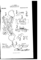
Figure 1 is a view showing a complete de vice; Figs. 2 and 8 are views showing a modified connection for the parts of the device, Fig. 2 being a face view, and Fig. 3, a section thereof; Fig. 4 is a detail View of a clip used in the construction shown in Fig. 1; Figs. 5, 6, 7, 8 and 9 are detail views showing modifications of the device illustrated in Fig. 1.
Referring first to Fig. 1, a, a, are two hoops of springy steel of any suitable kind, preferably hard silver hoop steel such as is used for saws. The ends of the strip of material forming each hoop are connected to gether by a suitable device allowing them to be disconnected when required. In Fig. 1 a metal piece Z) with its edges turned over as shown is riveted to one end of the strip a, and the other end is passed beneath the turned over edges of the piece 6 and is held in place by a bent metal holder 0 which is inserted through a hole in the end carrying the piece I) and in one of a series of holes in the other end of the strip. The holder 0 is so made as shown that it can be applied only in one position and when turned from that position will fill the two registering holes and will so prevent the ends of the strip from separating. The turned over edges 6 will prevent the ends from opening out so that they can only be separated by sliding longitudinally one upon the other. Slots are formed at d in each of the strips, and pins 6 with their ends riveted over or with washers upon them as shown are passed through the slots (Z to act as pivots connecting the one Specification of Letters Patent.
Application filed November 25, 1910.
Patented July 18, 1911.
Serial No. 594,135.
hoop a with the other. f, f, are metal stir rups each attached to one of the hoops a at a suitable point as forinstance by a bolt g, the hoop being preferably strengthened by an inserted metal piece it at the point of attachment of the stirrup. The edges of the hoops a may be roughened or notched in any suitable way to cause them to grip the pole, as indicated in Figs. 8 and 9 for example, wherein portions of both an upper and a lower curve of the hoops a are shown, with inwardly turned teeth y at their gripping edges; or pieces of hemp rope 70 or the like may be inserted in the hoops to form the gripping surfaces, as indicated in Fig. 1. The pieces of rope 70, if such are used, may be held in place by wires Z having their ends passed through holes in the hoops and twisted as shown to prevent them from being drawn through the holes, or any other suitable device may be used for binding the ropes 7c in place: At the ends where the ropes pass the attachment devices 6, c, the said ropes must be detachably held in place and for this purpose spring clips we may be provided formed for instance as indicated in the detail view, Fig. 4, with a loop to fit around the rope and with bent tongues to engage, over the edges of the hoop. Instead of the rope is being arranged as shown in Fig. 1, a rope may be used which is wrapped around the hoop a as indicated in the detail view, Fig. 5; or the gripping surface may be formed in any other suitable way as for instance by riveting a stout leather or indiarubber strip 1) in the hoop.
In place of the attachment device 7), c, any other suitable form of removable connection may be used. For instance, Figs. 2 and 3 show a modified construction. In this case one end of the hoop a has a metal piece or bridge a riveted around or otherwise attached to it, into which the other end of the hoop a, having a number of holes therein as shown, is inserted. The end carrying the bridge piece a has a spring tongue 0 riveted at g thereon, with a stud or pin 79 on its free end adapted to pass through registering holes in the two ends of the hoop a and through a hole'in the bridge piece 72. Upon the bridge piece at is arranged a slide 1" working in guides s and with a slot 25 in it to permit the passage of the head of the stud p, and to lock the latter as illustrated. A depression at u in the slide 1" engaging in a corresponding depression in the bridge piece n, will insure that the slide remains in the locking position unless forced away from the same. The pivots 6, instead of being formed as shown in Fig. 1, may for instance be formed by brass or other rivets or rollers m, as indicated in Fig. 7, passing through the slots at (Z in the hoops a and connecting the hoops together while forming pivots for the same.
The device above described is used as follows :VVhen a pole is to be sealed with the device, the connections at Z) of the ends of the hoops are opened, allowing the device to be applied to the pole at the base thereof, and then the connections are remade so as to close the hoops around the pole in approximately the position shown in Fig. 1 with the stirrups f at the bottom of each side. The dotted lines marked w in Fig. 1 represent a pole of small diameter to which the device is applied. If now the person who wishes to scale the pole places his feet in the stirrups f his weight will cause the hoops a to occupy an inclined position in which they will grip the pole as indicated, and the pins 6 in the slots (Z will permit of transverse movement of one hoop relatively to the other so that one hoop will not interfere with the adequate gripping of the other. The climber, standing erect, will hold the pole in his clasped arms or otherwise and will then draw up his legs when his feet will press against the tops of the stirrups so expanding the device by causing the hoops to turn around the pivots e and to come more nearly into the horizontal plane, whereby the device will be liberated from the pole, when it can be drawn up. The feet are then pressed downward and inward causing the device to grip the pole again and then the arm-hold on the pole is raised and the same operation repeated until the pole is scaled to any desired height. A similar device to that shown may also be used for engaging the pole by the hands if required, the hands holding upon the stirrups f or any other handles applied in place of the stirrups. Usually however it will be suflicient to provide the gripping device as shown for use with the feet, and the climber will rely upon his arms to hold the pole when raising the feet, and of course a belt or rope may be passed around the body of the climber and around the pole in the usual way to prevent accidents. For a pole of smaller size the hoops a would be reduced in size by connecting them together by the device 0 or otherwise at holes farther from the end of the strip, and where taper poles are used the diameters of the hoops will be set at the bottom of the pole to be only slightly larger than the diameter of the pole to be scaled;
then as the climber gets higher on the pole the angular movement of the device will be greater but owing to the flexibility of the hoops they will still effectually shape themselves to and grip the pole even when it is considerably smaller than the size of the aperture through. each of the hoops. The slots d, besides having the action above referred to in permitting the hoops to grip the pole independently of one another, also allow for the changes in the size of the hoops for different sizes of poles, and permit the stirrups f to be fixed on the hoops, these latter being turned to bring the stirrups to the mid-position between the pivot points when the sizes of the hoops are changed by means of the connections 7), c, or their equivalent. Of course however if the device is to be used on poles of a standard size only it need not necessarily be provided with an adjustable connection for each of the hoops, but the ends of the hoops may be arranged to be always connected together in one and the same position as will be obvious.
The invention is not limited to the exact construction or constructions described but modifications in matters of detail may be made without departing from the spirit of the invention.
I declare that what I claim is 1. In a gripping device for use in climbing poles, the combination of a pair of intersecting hoops, and means for pivotally connecting said hoops at their points of intersection, each hoop being flexible in a plane passing through the pivots, and substantially rigid in a plane perpendicular to the first plane; with attachments on the two members adapted to take the weight of the climber applied by the hands or feet to the said attachments.
2. In a gripping device for use in climbing poles, the combination of a pair of curved members flexible in one plane and substantially rigid in a plane at right-angles thereto, and means for connecting the ends of said curved members upon themselves to form closed hoops which are flexible in the plane of the circumference, but are substantially rigid in a plane at right-angles thereto; with means for pivotally connecting said members together, and attachments on the two members adapted to take the weight of the climber applied by the hands or feet to the said attachments.
3. In a gripping device for use in climbing poles, the combination of apair of flexible curved members with means for connecting the ends of said members upon themselves to form closed hoops of various sizes, slots in the said members and rivets passed through corresponding slots adapted to connect the two members pivotally together while permitting a certain amount of relative movement across the pivots, and attachments on the two members adapted to take the weight of the climber applied by the hands or feet to the said attachments.
4. In a gripping device for use in climbing poles, the combination of a pair of fieXible curved members With means for connecting the ends of said members upon themselves to form closed hoops of various sizes, gripping material applied to the inner faces of the curved members to form a resilient gripping surface, slots in the said members and rivets passed through corresponding slots adapted to connect the two members pivotally together while permitting a certain amount of relative movement across the pivots, and attachments on the two members adapted to take the Weight of the climber applied by the hands or feet to the said attachments.
5. lln a gripping device for use in climbing poles, the combination of a pair of hoops and means permitting said hoops to be opened out and closed on themselves as required, pivotal connections holding one hoop across and around the other, and means for applying the Weight of the person to each hoop at a point between the pivotal connections whereby the hoops are caused to grip the pole to which they are applied.
6. A gripping device for use in climbing poles, comprising a pair of flat hoops of flexible metal, each hoop provided with disconnectible means for connecting its ends together, two longitudinal slots in each hoop at positions which lie approximately at opposite ends of a diameter of the closed hoop, rivets connecting the two hoops together said rivets passing through the corresponding slots in the two hoops and holding one pivotally around the other, means for applying the weight of a person to each hoop at a position intermediate between the pivots, and gripping surfaces applied to the hoops at the places where the principal gripping action occurs.
In witness whereof, I have hereunto signed my name this 12th day of November 1910, in the presence of two subscribing witnesses.
EDWARD JOHNSON RIMMER.
Witnesses:
HUBERT ALEXANDER GILL, RICHARD LOVELL CLEAVER.
Copies of this patent may be obtained for five cents each, by addressing the Commissioner of Patents, Washington, D. C.
Priority Applications (1)
| Application Number | Priority Date | Filing Date | Title |
|---|---|---|---|
| US59413510A US998396A (en) | 1910-11-25 | 1910-11-25 | Climbing and scaling device. |
Applications Claiming Priority (1)
| Application Number | Priority Date | Filing Date | Title |
|---|---|---|---|
| US59413510A US998396A (en) | 1910-11-25 | 1910-11-25 | Climbing and scaling device. |
Publications (1)
| Publication Number | Publication Date |
|---|---|
| US998396A true US998396A (en) | 1911-07-18 |
Family
ID=3066725
Family Applications (1)
| Application Number | Title | Priority Date | Filing Date |
|---|---|---|---|
| US59413510A Expired - Lifetime US998396A (en) | 1910-11-25 | 1910-11-25 | Climbing and scaling device. |
Country Status (1)
| Country | Link |
|---|---|
| US (1) | US998396A (en) |
-
1910
- 1910-11-25 US US59413510A patent/US998396A/en not_active Expired - Lifetime
Similar Documents
| Publication | Publication Date | Title |
|---|---|---|
| US4787660A (en) | Rope puller | |
| US363495A (en) | Rope-hook | |
| US910238A (en) | Auxiliary handle for valises and bags. | |
| US998396A (en) | Climbing and scaling device. | |
| US490806A (en) | Baggage-check | |
| US1006584A (en) | Binder. | |
| US810254A (en) | Climbing apparatus. | |
| US2810504A (en) | Rope climbing device | |
| US632114A (en) | Exercising device. | |
| US633632A (en) | Wire-stretcher. | |
| DE3929974C1 (en) | Umbrella support belt and strap - has pocket on belt and hook on diagonal shoulder strap | |
| US157165A (en) | Improvement in spittoon lifters and holders | |
| US373017A (en) | Device for tightening bands | |
| US877418A (en) | Pole-climber. | |
| US821967A (en) | Carrying-handle. | |
| US605745A (en) | Handle | |
| US522882A (en) | Fastening for horse-blankets | |
| US390951A (en) | Hitching-post | |
| US410260A (en) | Fastening for reins | |
| US1020214A (en) | Belt-lacing tool. | |
| US1012587A (en) | Clothes-line fastener. | |
| US754731A (en) | Buckle. | |
| US705504A (en) | Wire-fence tool. | |
| US391307A (en) | Sleeve-holder | |
| US693764A (en) | Jewelry-securer. |