US9983627B1 - Hinge for a computing device with two display devices - Google Patents
Hinge for a computing device with two display devices Download PDFInfo
- Publication number
- US9983627B1 US9983627B1 US15/482,950 US201715482950A US9983627B1 US 9983627 B1 US9983627 B1 US 9983627B1 US 201715482950 A US201715482950 A US 201715482950A US 9983627 B1 US9983627 B1 US 9983627B1
- Authority
- US
- United States
- Prior art keywords
- housing
- bracket
- angle
- degrees
- computing device
- Prior art date
- Legal status (The legal status is an assumption and is not a legal conclusion. Google has not performed a legal analysis and makes no representation as to the accuracy of the status listed.)
- Active
Links
Images


Classifications
-
- G—PHYSICS
- G06—COMPUTING; CALCULATING OR COUNTING
- G06F—ELECTRIC DIGITAL DATA PROCESSING
- G06F1/00—Details not covered by groups G06F3/00 - G06F13/00 and G06F21/00
- G06F1/16—Constructional details or arrangements
- G06F1/1613—Constructional details or arrangements for portable computers
- G06F1/1633—Constructional details or arrangements of portable computers not specific to the type of enclosures covered by groups G06F1/1615 - G06F1/1626
- G06F1/1637—Details related to the display arrangement, including those related to the mounting of the display in the housing
- G06F1/1647—Details related to the display arrangement, including those related to the mounting of the display in the housing including at least an additional display
- G06F1/1649—Details related to the display arrangement, including those related to the mounting of the display in the housing including at least an additional display the additional display being independently orientable, e.g. for presenting information to a second user
-
- E—FIXED CONSTRUCTIONS
- E05—LOCKS; KEYS; WINDOW OR DOOR FITTINGS; SAFES
- E05D—HINGES OR SUSPENSION DEVICES FOR DOORS, WINDOWS OR WINGS
- E05D11/00—Additional features or accessories of hinges
- E05D11/0081—Additional features or accessories of hinges for transmitting energy, e.g. electrical cable routing
-
- E—FIXED CONSTRUCTIONS
- E05—LOCKS; KEYS; WINDOW OR DOOR FITTINGS; SAFES
- E05D—HINGES OR SUSPENSION DEVICES FOR DOORS, WINDOWS OR WINGS
- E05D11/00—Additional features or accessories of hinges
- E05D11/10—Devices for preventing movement between relatively-movable hinge parts
- E05D11/1028—Devices for preventing movement between relatively-movable hinge parts for maintaining the hinge in two or more positions, e.g. intermediate or fully open
- E05D11/105—Devices for preventing movement between relatively-movable hinge parts for maintaining the hinge in two or more positions, e.g. intermediate or fully open the maintaining means acting perpendicularly to the pivot axis
-
- E—FIXED CONSTRUCTIONS
- E05—LOCKS; KEYS; WINDOW OR DOOR FITTINGS; SAFES
- E05D—HINGES OR SUSPENSION DEVICES FOR DOORS, WINDOWS OR WINGS
- E05D7/00—Hinges or pivots of special construction
-
- G—PHYSICS
- G06—COMPUTING; CALCULATING OR COUNTING
- G06F—ELECTRIC DIGITAL DATA PROCESSING
- G06F1/00—Details not covered by groups G06F3/00 - G06F13/00 and G06F21/00
- G06F1/16—Constructional details or arrangements
- G06F1/1613—Constructional details or arrangements for portable computers
- G06F1/1615—Constructional details or arrangements for portable computers with several enclosures having relative motions, each enclosure supporting at least one I/O or computing function
- G06F1/1616—Constructional details or arrangements for portable computers with several enclosures having relative motions, each enclosure supporting at least one I/O or computing function with folding flat displays, e.g. laptop computers or notebooks having a clamshell configuration, with body parts pivoting to an open position around an axis parallel to the plane they define in closed position
- G06F1/1618—Constructional details or arrangements for portable computers with several enclosures having relative motions, each enclosure supporting at least one I/O or computing function with folding flat displays, e.g. laptop computers or notebooks having a clamshell configuration, with body parts pivoting to an open position around an axis parallel to the plane they define in closed position the display being foldable up to the back of the other housing with a single degree of freedom, e.g. by 360° rotation over the axis defined by the rear edge of the base enclosure
-
- G—PHYSICS
- G06—COMPUTING; CALCULATING OR COUNTING
- G06F—ELECTRIC DIGITAL DATA PROCESSING
- G06F1/00—Details not covered by groups G06F3/00 - G06F13/00 and G06F21/00
- G06F1/16—Constructional details or arrangements
- G06F1/1613—Constructional details or arrangements for portable computers
- G06F1/1633—Constructional details or arrangements of portable computers not specific to the type of enclosures covered by groups G06F1/1615 - G06F1/1626
- G06F1/1675—Miscellaneous details related to the relative movement between the different enclosures or enclosure parts
- G06F1/1681—Details related solely to hinges
-
- E—FIXED CONSTRUCTIONS
- E05—LOCKS; KEYS; WINDOW OR DOOR FITTINGS; SAFES
- E05D—HINGES OR SUSPENSION DEVICES FOR DOORS, WINDOWS OR WINGS
- E05D11/00—Additional features or accessories of hinges
- E05D11/10—Devices for preventing movement between relatively-movable hinge parts
- E05D2011/1092—Devices for preventing movement between relatively-movable hinge parts the angle between the hinge parts being adjustable
-
- E—FIXED CONSTRUCTIONS
- E05—LOCKS; KEYS; WINDOW OR DOOR FITTINGS; SAFES
- E05D—HINGES OR SUSPENSION DEVICES FOR DOORS, WINDOWS OR WINGS
- E05D3/00—Hinges with pins
- E05D3/06—Hinges with pins with two or more pins
-
- E—FIXED CONSTRUCTIONS
- E05—LOCKS; KEYS; WINDOW OR DOOR FITTINGS; SAFES
- E05Y—INDEXING SCHEME RELATING TO HINGES OR OTHER SUSPENSION DEVICES FOR DOORS, WINDOWS OR WINGS AND DEVICES FOR MOVING WINGS INTO OPEN OR CLOSED POSITION, CHECKS FOR WINGS AND WING FITTINGS NOT OTHERWISE PROVIDED FOR, CONCERNED WITH THE FUNCTIONING OF THE WING
- E05Y2900/00—Application of doors, windows, wings or fittings thereof
- E05Y2900/60—Application of doors, windows, wings or fittings thereof for other use
- E05Y2900/606—Application of doors, windows, wings or fittings thereof for other use for electronic devices
Definitions
- This invention relates generally to computing devices with two display devices and, more particularly, to a hinge that can rotate approximately 360 degrees and, when the hinge is at approximately 180-degrees, bring the two display devices close to each other (e.g., 4 millimeters (mm) or less).
- An information handling system generally processes, compiles, stores, and/or communicates information or data for business, personal, or other purposes thereby allowing users to take advantage of the value of the information.
- information handling systems may also vary regarding what information is handled, how the information is handled, how much information is processed, stored, or communicated, and how quickly and efficiently the information may be processed, stored, or communicated.
- the variations in information handling systems allow for information handling systems to be general or configured for a specific user or specific use such as financial transaction processing, airline reservations, enterprise data storage, or global communications.
- information handling systems may include a variety of hardware and software components that may be configured to process, store, and communicate information and may include one or more computer systems, data storage systems, and networking systems.
- laptops may include a display device in a first housing and one or more input devices (e.g., keyboard, touchpad, and the like) in a second housing.
- the first housing may be connected to the second housing using a hinge.
- Some laptops may provide 2-in-1 functionality using hinges that can position the two housings at 360 degrees relative to each other.
- the computing device may be used as a conventional laptop when the two housings are positioned at 180-degrees or less relative to each other and the computing device may be used as a tablet when the two housings are positioned at 360 degrees relative to each other.
- the distance between the two housings at various angles between 0 and 360 degree may not be particularly important to the user.
- the distance between the two housings may be important to the user.
- a computing device may include a first housing and a second housing attached by one or more hinges.
- the first housing may house a first set of components, including a first display device.
- the second housing may house a second set of components, including a second display device.
- the one or more hinges may enable the first housing and the second housing to be placed at an angle of between about 0 degrees to about 360 degrees relative to each other. When the first housing is placed at an angle of about 180 degrees relative to the second housing, the one or more hinges may pull the first housing and the second housing towards each other, resulting in a gap between a first edge of the first housing and a second edge of the second housing of 2 millimeters or less.
- FIGS. the left-most digit(s) of a reference number identifies the FIG. in which the reference number first appears.
- the same reference numbers in different FIGS. indicate similar or identical items.
- FIG. 1 is a block diagram of an internal architecture of a computing device that includes two display devices (e.g., a dual-display device) according to some embodiments.
- FIG. 2 is a block diagram illustrating different orientations of a dual-display device according to some embodiments.
- FIG. 3 is a block diagram illustrating vertical orientations of a dual-display device according to some embodiments.
- FIG. 4 is a block diagram illustrating horizontal orientations of a dual-display device according to some embodiments.
- FIG. 5 is a block diagram illustrating different display modes of a dual-display device according to some embodiments.
- FIG. 6 is a block diagram of a hinge according to some embodiments.
- FIG. 7 is a block diagram of a particular view of components of a hinge according to some embodiments.
- FIG. 8 is a block diagram illustrating a distance between two display devices in a 180-degree position according to some embodiments.
- FIG. 9 is a block diagram of components of a hinge in in which two housings are positioned at approximately 0 degrees and approximately 30 degrees relative to each other according to some embodiments.
- FIG. 10 is a block diagram of components of a hinge in in which two housings are positioned at approximately 90 degrees and approximately 120 degrees relative to each other according to some embodiments.
- FIG. 11 is a block diagram of components of a hinge in in which two housings are positioned approximately 175 degrees relative to each other according to some embodiments.
- FIG. 12 is a block diagram of a hinge in which two housings are positioned at approximately 180-degrees relative to each other according to some embodiments.
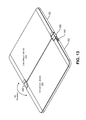
- FIG. 13 is a block diagram of a computing device in which two housings are positioned at approximately 180-degrees relative to each other according to some embodiments.
- FIG. 14 is a block diagram of a computing device in which two housings are positioned at approximately 270-degrees and approximately 360-degrees relative to each other according to some embodiments.
- FIG. 15 illustrates an example configuration of a computing device that can be used to implement the systems and techniques described herein.
- an information handling system may include any instrumentality or aggregate of instrumentalities operable to compute, calculate, determine, classify, process, transmit, receive, retrieve, originate, switch, store, display, communicate, manifest, detect, record, reproduce, handle, or utilize any form of information, intelligence, or data for business, scientific, control, or other purposes.
- an information handling system may be a personal computer (e.g., desktop or laptop), tablet computer, mobile device (e.g., personal digital assistant (PDA) or smart phone), server (e.g., blade server or rack server), a network storage device, or any other suitable device and may vary in size, shape, performance, functionality, and price.
- PDA personal digital assistant
- the information handling system may include random access memory (RAM), one or more processing resources such as a central processing unit (CPU) or hardware or software control logic, ROM, and/or other types of nonvolatile memory. Additional components of the information handling system may include one or more disk drives, one or more network ports for communicating with external devices as well as various input and output (I/O) devices, such as a keyboard, a mouse, touchscreen and/or video display. The information handling system may also include one or more buses operable to transmit communications between the various hardware components.
- RAM random access memory
- processing resources such as a central processing unit (CPU) or hardware or software control logic, ROM, and/or other types of nonvolatile memory.
- Additional components of the information handling system may include one or more disk drives, one or more network ports for communicating with external devices as well as various input and output (I/O) devices, such as a keyboard, a mouse, touchscreen and/or video display.
- I/O input and output
- the information handling system may also include one or more buses operable to transmit
- the systems and techniques described herein may enable a tablet computing device with two display devices connected to each other by one or more hinges to be positioned in a way that enables a user to utilize the two display devices in a manner similar to a single, larger display device.
- the hinges may enable the two display devices to rotate relative to each other from between about 0 degrees to about 360 degrees.
- the user may desire to have the two display devices fairly close to each other, e.g., such that the two display devices appear (and behave) similar to a single display device.
- the tablet computing device may be relatively compact (e.g., 8′′ ⁇ 5′′) when the two display devices are about 0 degrees (e.g., closed position) to enable the computing device to be easily stored and transported.
- the long edge of the first display device may be placed close (e.g., 4 mm or less) to the long edge of the second display device, enabling the user to use the two display devices as if they were a single larger (e.g., 8′′ ⁇ 10′′) display device.
- positioning the two display devices approximately 180-degrees relative to each other may enable the user to work on documents, presentations, or spreadsheets, view videos, and the like using about double the surface area as compared to each individual display device.
- a bezel around each display device may be relatively narrow (e.g., 2 mm or less), at least along the long edge to which the hinge is attached.
- the hinges may use a mechanism (as described herein) to draw the long edges of the two display devices close to each other when the display devices are positioned approximately 180-degrees to each other, to enable the gap between the long edge of the first display device and the long edge of the second display device to be relatively small.
- a computing device may include a first housing coupled to a second housing by one or more hinges.
- the first housing may house a first set of components, including a first display device.
- the second housing may house a second set of components, including a second display device.
- the one or more hinges may enable the first housing to be placed at an angle of between about 0 degrees to about 360 degrees relative to the second housing.
- Placing the first housing at an angle of about 180 degrees relative to the second housing may cause the one or more hinges to (i) pull the first housing 2 millimeters (or less) towards the second housing and (ii) pull the second housing 2 millimeters (or less) towards the second housing, causing a gap between a first edge of the first housing and a second edge of the second housing to be 2 millimeters or less and causing a gap between a first particular edge of the first display device and a second particular edge of the second display device to be 4 millimeters or less.
- An individual hinge of the one or more hinges may include: (i) a first bracket attached to the first housing, (ii) a second bracket attached to the second housing, (iii) a first bracket holder that is attached to the first bracket, and (iv) a second bracket holder that is attached to the second bracket.
- the individual hinge may also include: (i) a first spring in which a first end of the first spring is attached to the first bracket and a second end of the first spring is attached to the first bracket holder, and (ii) a second spring in which the first end of the second spring is attached to the second bracket and the second end of the second spring is attached to the second bracket holder.
- Placing the first housing at the angle of about 180 degrees relative to the second housing may cause the first spring to exert a predetermined amount of force on the first bracket holder, thereby pulling the first edge of the first housing towards the second housing and cause the second spring to exert the predetermined amount of force on the second bracket holder, thereby pulling the second edge of the second housing towards the first housing.
- the individual hinge may also include: (i) a first position pin attached to the first bracket holder, (ii) a first slot in the first bracket in which the first position pin moves from a first end of the first slot to a second end of the first slot based on the angle between the first housing and the second housing, (iii) a second position pin attached to the second bracket holder, and (iv) a second slot in the second bracket in which the second position pin moves from the first end of the second slot to the second end of the second slot based on the angle between the first housing and the second housing.
- a computing device may include a first housing coupled to a second housing by at least one hinge.
- the first housing may include a first set of components (e.g., processors, memory, sensors, and the like) including a first display device.
- the second housing may include a second set of components (battery, battery charger, sensors, and the like) including a second display device.
- the at least one hinge may enable the first housing to be placed at an angle of between about 0 degrees to about 360 degrees relative to the second housing.
- placing the first housing at an angle of about 180 degrees relative to the second housing may cause the one or more hinges to pull a first edge of the first housing 2 millimeters (or less) towards the second housing and pull a second edge of the second housing 2 millimeters (or less) towards the second housing.
- the at least one hinge may include one or more conduits through which at least one cable is routed.
- the at least one cable may carry power from a power source in the second housing to the first set of components in the first housing.
- the at least one cable may carry one or more data signals between the first set of components in the first housing and the second set of components in the second housing.
- the at least one hinge may include a plurality of detents associated to temporarily hold the first housing at an angle relative to the second housing.
- the at least one hinge may include detents at angles of about 0 degrees, about 90 degrees, about 180 degrees, and about 360 degrees.
- the at least one hinge may include a locking mechanism to enable the at least one hinge to temporarily lock the first housing and the second housing at a first particular angle.
- a button (or other mechanism) may be used to unlock the locking mechanism when changing the angle of the first housing relative to the second housing from the first particular angle to a second particular angle.
- a computing device may include a first housing coupled to a second housing by one or more hinges.
- the first housing may be used to house a first set of components and the second housing may be used to house a second set of components.
- the one or more hinges may enable the first housing and the second housing to be placed at an angle of between about 0 degrees to about 360 degrees relative to each other. Placing the first housing at an angle of about 180 degrees relative to the second housing may cause the two housings to be pulled closer to each other, such that a gap between a first edge of the first housing and a second edge of the second housing is 2 millimeters (or less).
- placing the first housing and the second housing at an angle of about 180 degrees relative to each other may cause the one or more hinges to: (i) pull the first edge of the first housing 2 millimeters or less towards the second housing, and (ii) pull the second edge of the second housing 2 millimeters or less towards the first housing.
- the first set of components may include a graphics processing unit (GPU) and a first display device connected to an embedded DisplayPort (eDP) output of the GPU.
- eDP embedded DisplayPort
- the second set of components may include a second display device connected to a DisplayPort (DP) output of the GPU.
- An individual hinge of the one or more hinges may include: (i) a first bracket attached to the first housing, (ii) a second bracket attached to the second housing, (iii) a first bracket holder that is attached to the first bracket, and (iv) a second bracket holder that is attached to the second bracket.
- the individual hinge may also include a first spring in which a first end of the first spring is attached to the first bracket and a second end of the first spring is attached to the first bracket holder, and a second spring in which the first end of the second spring is attached to the second bracket and the second end of the second spring is attached to the second bracket holder.
- Placing the first housing at the angle of about 180 degrees relative to the second housing may (i) cause the first spring to exert a predetermined amount of force on the first bracket holder, thereby pulling the first edge of the first housing towards the second housing, and (ii) cause the second spring to exert the predetermined amount of force on the second bracket holder, thereby pulling the second edge of the second housing towards the first housing.
- the individual hinge may also include (i) a first position pin attached to the first bracket holder, (ii) a first slot in the first bracket in which the first position pin moves from a first end of the first slot to a second end of the first slot based on the angle between the first housing and the second housing, (iii) a second position pin attached to the second bracket holder, and (iv) a second slot in the second bracket in which the second position pin moves from the first end of the second slot to the second end of the second slot based on the angle between the first housing and the second housing.
- FIG. 1 is a block diagram of an internal architecture 100 of a computing device that includes two display devices (e.g., a dual-display device) according to some embodiments.
- the computing device 100 may include a first housing 102 coupled to a second housing 104 via one or more hinges 106 .
- the hinges 106 may enable the two housings 102 , 104 to be positioned at different angles (e.g., between about 0 to about 360 degrees) relative to each other and in different orientations (e.g., vertical orientations and horizontal orientations).
- a first display device 108 may be located in the first housing 102 and a second display device 110 may be located in the second housing 104 .
- the display devices 108 , 110 may use a technology such as liquid crystal display (LCD), light emitting diode (LED), organic LED (OLED), electronic paper (e-paper), electronic ink (e-ink), or the like.
- LCD liquid crystal display
- LED light emitting diode
- OLED organic LED
- a first portion of the components of the computing device 100 may be located in the first housing 102 (e.g., behind the first display device 108 ) while a remaining portion of the components of the computing device 100 may be located in the second housing 104 (e.g., behind the second display device 110 ).
- the components located in the first housing 102 may include at least one central processing unit (CPU) 112 , a graphics process unit (GPU) 114 , and a memory (e.g., computer-readable media) 114 .
- the GPU 114 may be integrated into the CPU 112 or may be a separate device from the GPU 114 .
- the CPU 112 and GPU 114 may be connected to a first input/output (I/O) bus 118 that provides a first set of one or more I/O ports 120 in the first housing 102 and a second I/O bus 122 that is connected to the second housing to provide a second set of one or more ports 128 .
- the ports 120 , 128 may include video ports, such as a video graphics adapter (VGA) port, a digital video interface (DVI) port, a high definition media interface (HDMI) port, a ThunderBolt® port, audio ports (e.g., microphone jack, headphone, jack, and the like), another type of signal port, or any combination thereof.
- VGA video graphics adapter
- DVI digital video interface
- HDMI high definition media interface
- ThunderBolt® port ThunderBolt® port
- audio ports e.g., microphone jack, headphone, jack, and the like
- the ports 120 , 128 may include one or more universal serial bus (USB) ports compliant with USB 2.0, USB 3.0, and the like.
- the ports 120 , 128 may include an Ethernet port, audio I/O ports, and the like.
- the GPU 114 may include two or more lanes of an embedded DisplayPort (eDP) output 124 connected to the first display device 108 in the first housing and two or more lanes of a DisplayPort (DP) output 126 that is connected to the second display device 110 in the second housing 104 .
- eDP embedded DisplayPort
- DP DisplayPort
- the second housing 104 may include a remaining portion of the components of the computing device 100 .
- the remaining portion of the components may be located in the second housing 104 (e.g., behind the second display device 110 ).
- the second housing 104 may include additional components 130 (e.g., keyboard, touchpad, trackball, speaker, microphone, Wi-Fi antenna, Bluetooth antenna, cellular antenna, and the like), a power input 132 (e.g., alternating current (AC) or direct current (DC) input), a charger 134 , and a battery 136 .
- the battery charger 134 may also be used as a power source to provide power instead of (or in addition to) the battery 250 , e.g., when the battery 136 is depleted or inoperable.
- a first power distribution bus in the first housing 102 may receive power from the battery 136 (or the charger 134 ) and distribute the power to the components in the first housing 102 .
- a second power distribution bus in the second housing 104 may distribute power from the battery 136 (or the charger 134 ) to the components in the second housing 104 .
- a cable threaded through one or more of the hinges 106 may be used to connect the first power distribution bus in the first housing 102 to the second power distribution bus in the second housing 104 and to the battery 136 and the charger 134 .
- the first set of components of the computing device 100 shown as being housed in the first housing 102 and the remaining set of components shown in the second housing 104 are purely for illustration purposes. Depending on the implementation, different components may be housed in each of the housings 102 , 104 .
- the GPU 114 and supporting hardware e.g., graphics support chips, graphics memory, and the like
- the ports 120 , 128 may all be located in the first housing 102 or in the second housing 104 rather than being split between the two housings 102 , 104 .
- the battery 136 may include multiple cells, with a portion of the cells located in the first housing 102 and a remaining portion of the cells located in the second housing 104 .
- which components of the computing device 100 are located in each of the housings 102 , 104 may be determined on the thermal characteristics of the components.
- the components may be distributed between the housings 102 , 104 to enable each of the housings 102 , 104 to heat up to approximately the same temperature. Doing so may avoid the situation where components that generate the most heat are grouped into the same housing, thereby causing one housing to be hotter than the other housing.
- Various sensors such as a magnetometer, a compass, an inertial sensor, a global positioning satellite sensor, an accelerometer, a gyroscope, a compass, a barometer, an imaging sensor (e.g., camera with lens), or other type of sensor may be located in one or both of the housings 102 , 104 .
- sensors such as a magnetometer, a compass, an inertial sensor, a global positioning satellite sensor, an accelerometer, a gyroscope, a compass, a barometer, an imaging sensor (e.g., camera with lens), or other type of sensor may be located in one or both of the housings 102 , 104 .
- a computing device 100 may include the first housing 102 connected to the second housing 104 by one or more hinges 106 .
- the hinges 106 may enable the first housing 102 and the second housing 104 to be placed at an angle between about 0 degrees to about 360 degrees.
- a first portion (e.g., first set) of components e.g., 112 , 114 , 116 , and 120 ) may be located in the first housing 102 (e.g., behind the first display device 108 ) of the dual-display computing device 100 .
- a remaining portion (e.g., second set) of the components may be located in the second housing 104 (e.g., behind the second display device 110 ) of the dual-display computing device 100 .
- FIG. 2 is a block diagram illustrating different orientations of a dual-display device (e.g., the computing device 100 of FIG. 1 ) according to some embodiments.
- the computing device 100 may include at least two display devices, the first display device 108 and the second display device 110 .
- the computing device 100 may be placed in a vertical (e.g., portrait) orientation 202 or a horizontal (e.g., landscape) orientation 204 .
- the first display device 108 may be on one side (e.g., the left side or the right side)
- the second display device 110 may be on another side (e.g., the right side or the left side)
- the hinges 106 may join the first display device 108 to the second display device 110 .
- the first display device 108 may be located at the top (or the bottom) of the computing device 100 , with the hinges 106 in the middle, and the second display device 110 at the bottom (or the top) of the computing device.
- FIG. 3 is a block diagram illustrating vertical orientations of a dual-screen device (e.g., the computing device 100 of FIG. 1 ) according to some embodiments.
- the vertical orientation 202 may include a book orientation 302 or a vertical tablet orientation 304 .
- first book orientation 302 ( 1 ) the first display device 108 may be on the left and the second display device 110 may be on the right.
- second book orientation 302 ( 2 ) the second display device 110 may be on the left and the first display device 108 may be on the right.
- the first display device 108 may be on the left and the second display device 110 may be on the right.
- the first display device 108 may be facing a user and the second display device 110 may be rotated approximately 360 degrees to face away from the user.
- the second display device 110 may be facing the user while the first display device 108 may rotated approximately 360 degrees to face away from the user.
- FIG. 4 illustrates horizontal orientations of a dual-screen device (e.g., the computing device 100 of FIG. 1 ) according to some embodiments.
- Examples of the horizontal orientation 404 may include a tent orientation 402 , a presentation orientation 404 , a horizontal tablet orientation 406 , and a clamshell orientation 408 .
- the first display device 108 may be at the top facing the user while the second display device 110 may be at the bottom facing away from the user.
- the second display device 110 may be at the top facing the user and the first display device 108 may be at the bottom facing away from the user.
- the first display device 108 may be at the top facing the user and the second display device 110 may be at the bottom facing down.
- the second display device 110 may be at the top facing the user and the first display device 108 may be at the bottom facing down.
- the first display device 108 may be at the top facing the user and the second display device 110 may be at the bottom facing down (e.g., away from the user).
- the second display device 110 may be at the top facing the user and the first display device 108 may be at the bottom facing down (e.g., away from the user).
- the first display device 108 may be at the top facing the user and the second display device 110 may be at the bottom facing the user (e.g., in a position where traditionally, a keyboard is located in a laptop).
- a QWERTY-based keyboard may be displayed on the second display device 110 and used to receive keyboard input.
- the second display device 110 may be at the top facing the user and the first display device 108 may be at the bottom facing the user (e.g., in a position where traditionally, a keyboard is located in a laptop).
- a QWERTY-based keyboard may be displayed on the first display device 108 and used to receive keyboard input.
- FIG. 5 is a block diagram illustrating different display modes of a dual-display device (e.g., the computing device 100 of FIG. 1 ) according to some embodiments.
- the top half of FIG. 5 illustrates when a display mode of an operating system of the dual-display device is set to display content in a clone mode or in a single display mode.
- first content 502 may be displayed both on the first display device 108 and on the second display device 110 .
- the first content 502 may be displayed on either (but not both) of the first display device 108 or the second display device 110 .
- the bottom half of FIG. 5 illustrates when a display mode of an operating system of the dual-display device is set to display content in an extended display mode, in which the second display device 110 is setup as an extension of the first display device 108 .
- some content such as the first content 502
- additional content may be displayed on either the first display device 108 or the second display device 110 .
- second content 504 may be displayed on the first display device 108 and third content 506 may be displayed on the second display device 110 .
- the hinge 106 may operate to reduce a distance between (i) the right edge of the first display device 108 and (ii) the left edge of the second display device 110 . In this way, the user may interact with the display devices 108 , 110 in a manner similar to a single (e.g., contiguous) display device. For example, the hinge 106 may position the right edge of the first display device 108 about 4 mm or less from the left edge of the second display device 110 .
- FIG. 6 is a block diagram of a hinge (one of the hinges 106 of FIG. 1 ) according to some embodiments.
- a spring 602 is connected to a bracket holder 604 and to a bracket 606 .
- the bracket holder 604 may slide up and down (in the orientation illustrated in FIG. 6 ) as the two housings 102 , 104 are rotated, as illustrated by the arrow in FIG. 6 .
- the bracket 606 may be fixed in place and may not move.
- a position pin 608 that is attached to the bracket holder 604 may slide back and forth within a slot (e.g., opening) in the bracket 606 .
- the position pin 608 may position the bracket holder 604 relative to the bracket 604 .
- the position pin 608 may be positioned as illustrated in FIG.
- the position pin 608 may move when the angle between the housings 102 , 104 is about 0 degrees.
- the bracket holder 604 may move a distance 612 as the hinge 106 moves from 0 degrees to 180-degrees or from 180-degrees to 360 degrees.
- the distance 612 may be about 2 mm or less and preferably 1.5 mm or less.
- a hinge edge 616 (e.g., an edge of a housing to which the hinge 106 is attached) of the first housing 102 and a hinge edge 618 of the second housing 104 may be pulled towards each other to reduce a gap between the housings 102 , 104 to within less than a predetermined amount (e.g., preferably 4 mm or less and most preferably 2 mm or less).
- a predetermined amount e.g., preferably 4 mm or less and most preferably 2 mm or less.
- the hinge 1606 may pull the housings 102 , 104 towards each other such that a distance between the hinge edge 616 (e.g., a first edge of the first housing) and the hinge edge 618 (e.g., a second edge of the second housing) is less than the predetermined amount (e.g., enabling a user to use the display devices 108 , 110 of FIG. 1 in a manner similar to a single display device).
- a distance between the hinge edge 616 e.g., a first edge of the first housing
- the hinge edge 618 e.g., a second edge of the second housing
- the hinge 106 may include a conduit or trough for one or more cables, such as a representative cable 610 .
- the cable 610 may carry power, data signals, or both between components in the housing 102 and components in the housing 104 .
- the hinge 106 comprises a dual pivot hinge with two halves. Each half includes a slot for the hinge bracket holder 606 to slide, which enables the two halves of the hinge 106 to slide close together in the 180-degree position.
- the position of the hinge bracket 604 is driven by the two halves of the hinge 106 contacting each other with the aid of the torsion spring 602 .
- Detents in the bracket holder 606 can be designed for certain positions (e.g., 0 degrees, 90 degrees, 180-degrees, 270 degrees, 360 degrees, and the like) to enable the user to place the housings 102 , 104 at a particular angle and have the housings 102 , 104 remain at the particular angle.
- the housings 102 , 104 may not change in angle due to minor jostling and incidental contact.
- the user may apply a minimum amount of force to overcome the detents and change the angle of the housings 102 , 104 .
- the dual pivot hinge 106 may slide between the housings 102 , 104 to enable the display devices 108 , 110 (of FIG. 1 ) to be relatively close (e.g., 4 mm or less) together, particularly in the 180-degree position.
- the arms 614 may make contact with each other, thereby pushing the bracket holder 604 the distance 612 (e.g., the top bracket holder 604 may move up while the bottom bracket holder 604 may move down), causing the two housings 102 , 104 to be positioned close to each other.
- the two display devices may be used as a single nearly contiguous display device.
- FIG. 7 is a block diagram of a particular view of components of a hinge according to some embodiments.
- FIG. 7 shows an upper side perspective to illustrate additional details of the hinge 106 .
- the spring 602 is connected to the bracket holder 604 and to the bracket 606 .
- the bracket holder 604 may slide as the two housings 102 , 104 are rotated, as illustrated by the arrows.
- the bracket 606 may be fixed in place and may not move.
- the position pin 608 may be attached to the bracket holder 604 and may slide back and forth within a slot (e.g., opening) in the bracket 606 .
- the position pin 608 may position the bracket holder 604 relative to the bracket 604 .
- the position pin 608 may be positioned as illustrated in FIG.
- the position pin 608 may move when the angle between the housings 102 , 104 is about 0 degrees.
- the bracket holder 604 may move the distance 612 as the hinge 106 moves from 0 degrees to 180-degrees or from 180-degrees to 360 degrees.
- the distance 612 may be about 2 mm or less and preferably 1.5 mm or less.
- the hinge 106 may include a conduit or trough for one or more cables, such as the cable 610 , to carry power, data signals, or both between the two housings 102 , 104 .
- the hinge 106 comprises a dual pivot hinge with two halves. Each half includes a slot for the hinge bracket holder 606 to slide, which enables the two halves of the hinge 106 to slide close together in the 180-degree position.
- the position of the hinge bracket 604 is driven by the two halves of the hinge 106 contacting each other with the aid of the torsion spring 602 .
- Detents in the bracket holder 606 can be designed for certain positions (e.g., 0 degrees, 90 degrees, 180-degrees, 270 degrees, 360 degrees, and the like) to enable the user to place the housings 102 , 104 at a particular angle and have the housings 102 , 104 remain at the particular angle.
- the housings 102 , 104 may not change in angle due to minor jostling and incidental contact.
- the user may apply a minimum amount of force to overcome the detents and change the angle of the housings 102 , 104 .
- the arms 614 may make contact with each other, thereby pushing the bracket holder 604 the distance 612 (e.g., the top bracket holder 604 may move up while the bottom bracket holder 604 may move down), causing the two housings 102 , 104 to be positioned close to each other.
- the two display devices may be used as a single nearly contiguous display device.
- FIG. 8 is a block diagram illustrating a distance between two display devices in a 180-degree position according to some embodiments.
- a glass surface 802 may be placed in front of the display devices 108 , 110 (e.g., LCD, LED, OLED, e-ink, or the like).
- Each of the housings 102 , 104 may include an outer case 804 .
- the case 804 may be made from plastic (e.g., polycarbonate or the like), metal, glass, wood, or any combination thereof.
- the hinge 106 may include one or more conduits 806 through which one or more cables 610 may be threaded.
- the cables 610 may carry (e.g., transmit) power, carry data signals, or both between components in the housing 102 and components in the housing 104 .
- the display devices 108 , 110 may not have a bezel on the side where the hinge 106 is attached (or the bezel may be very narrow).
- the distance between a visible edge of the display devices 108 , 110 and an outer edge of the case 804 may be a distance 808 .
- the distance 808 may be 2 mm or less (preferably 1 mm or less).
- the distance between an edge of the display device 108 and an edge of the display device 110 may be a distance 810 .
- the distance 810 may be 4 mm or less (preferably 2 mm or less). In this way, the display devices 108 , 110 may appear to the user as a single (near contiguous) display device.
- FIG. 9 is a block diagram of components of a hinge in in which two housings are positioned at approximately 0 degrees and approximately 30 degrees relative to each other according to some embodiments.
- FIG. 9 illustrates the movement of the various parts of the hinge 106 as the housings 102 , 104 are moved from 0 degrees (top of FIG. 9 ) to about 30 degrees (bottom of FIG. 9 ) relative to each other.
- the two bracket holders 604 begin to touch.
- the arms 614 begin to touch, putting pressure on the bracket holders 604 to move (e.g., slide) away from each other.
- the position pins 608 begin to move closer to each other.
- FIG. 10 is a block diagram of components of a hinge in in which two housings are positioned at approximately 90 degrees and approximately 120 degrees relative to each other according to some embodiments.
- FIG. 10 illustrates the movement of the various parts of the hinge 106 as the housings 102 , 104 are moved from about 90 degrees (top of FIG. 10 ) to about 120 degrees (bottom of FIG. 10 ) relative to each other.
- the two bracket holders 604 are touching and internally (e.g., in the hinge 106 ), the arms 614 are putting pressure on the bracket holders 604 to move (e.g., slide) away from each other.
- the position pins 608 continue to move closer to each other.
- the two bracket holders 604 continue to touch.
- the arms 614 continue to put pressure on the bracket holders 604 to move (e.g., slide) away from each other.
- the position pins 608 continue to move closer to each other.
- FIG. 11 is a block diagram of components of a hinge in in which two housings are positioned approximately 175 degrees relative to each other according to some embodiments. At 175 degrees, the two bracket holders 604 continue to touch. Internally (e.g., in the hinge 106 ), the arms 614 have put enough pressure to slide the bracket holders 604 such that the position pins 608 have moved nearly as close as possible to each other (as compared to the 0-degree position).
- FIG. 12 is a block diagram of a hinge in which two housings are positioned at approximately 180-degrees relative to each other according to some embodiments. At about 180 degrees, the two bracket holders 604 touch each other or almost (less than 1 mm distance) touch other. Internally (e.g., in the hinge 106 ), the arms 614 have caused the bracket holders 604 to move such that the position pins 608 have moved as close as possible to each other (as compared to the 0-degree position).
- FIG. 13 is a block diagram of a computing device in which two housings are positioned at approximately 180-degrees relative to each other according to some embodiments.
- FIG. 13 illustrates how the computing device appears when the housings 102 , 104 are at an angle of about 180 degrees relative to each other.
- detents in the hinges 106 may be designed to temporarily hold the housings 102 , 104 at certain angles, e.g., 0 degrees, 90 degrees, 180-degrees, 270 degrees, 360 degrees, and the like.
- the detents may enable the user to place the housings 102 , 104 at a particular angle and have the housings 102 , 104 remain at the particular angle.
- the hinges 106 may include a locking mechanism that temporarily “locks” the housings 102 , 104 after the housings 102 , 104 have been placed at a particular angle (e.g., 0 degrees, 90 degrees, 180-degrees, 270 degrees, 360 degrees, and the like) relative to each other.
- a particular angle e.g., 0 degrees, 90 degrees, 180-degrees, 270 degrees, 360 degrees, and the like
- the bracket holders 604 (or the position pins 608 ) of FIG. 6 and FIG. 7 may be temporarily be locked in place.
- the temporary lock may enable the housings 102 , 104 to remain at the particular angle even if the computing device 100 encounters minor jostling or the like.
- the user may press a button 1302 to unlock the locking mechanism and move the housings 102 , 104 from a first angle to a second angle (e.g., the second angle is different from the first angle).
- the computing device 100 may be locked in a closed position in which the housings 102 , 104 are at about 0 degrees relative to each other, to enable the user to transport the computing device 100 .
- the user may press the button 1302 , causing the locking mechanism to unlock, enabling the user to move the housings 102 , 104 to an open position.
- the user may press the button 1302 and move the housings 102 , 104 from 0 degrees to about 180 degrees relative to each to use the display devices 108 , 110 as if they were a single display device.
- buttons 1302 While the button 1302 is illustrated in FIG. 13 as being at the bottom of the first housing, the button 1302 may be located at the bottom or the top of either housing 102 or 104 . The button 1302 may be located close to one of the hinges 106 to enable the button to easily interact with the locking mechanism.
- FIG. 14 is a block diagram of a computing device in which two housings are positioned at approximately 270-degrees and approximately 360-degrees relative to each other according to some embodiments.
- FIG. 14 illustrates the movement of the various parts of the hinge 106 as the housings 102 , 104 are moved from about 270 degrees (top of FIG. 14 ) to about 360 degrees (bottom of FIG. 14 ) relative to each other.
- the arms 614 may reduce the amount of pressure applied to allow the bracket holders 604 to slide such that the position pins 608 move further apart as the angle increases from 180 to 270 and then 360.
- FIG. 15 illustrates an example configuration of the computing device 100 of FIG. 1 that can be used to implement the systems and techniques described herein.
- the computing device 100 may include one or more processors 1502 (e.g., the CPU 112 and the GPU 114 of FIG. 1 ), the memory 116 , communication interfaces 1506 (e.g., the I/O ports 120 , 128 ), the display devices 108 , 110 , other input/output (I/O) devices 1510 (e.g., keyboard, trackball, and the like), and one or more mass storage devices 1512 (e.g., disk drive, solid state drive, or the like), configured to communicate with each other, such as via one or more system buses 1514 or other suitable connection. While a single bus 1514 is illustrated for ease of understanding, it should be understood that the system buses 1514 may include multiple buses, such as memory device buses, storage device buses, data buses, video signal buses, and the like.
- the processors 1502 are one or more hardware devices that may include a single processing unit or a number of processing units, all of which may include single or multiple computing units or multiple cores.
- the processors 1502 may include the GPU 114 integrated into the CPU 112 or the GPU 114 may be a separate processor device from the CPU 112 .
- the processors 1502 may be implemented as one or more microprocessors, microcomputers, microcontrollers, digital signal processors, central processing units, graphics processing units, state machines, logic circuitries, and/or any devices that manipulate signals based on operational instructions.
- the processors 1502 may be configured to fetch and execute computer-readable instructions stored in the memory 116 , mass storage devices 1512 , or other computer-readable media.
- Memory 116 and mass storage devices 1512 are examples of non-transitory computer media (e.g., memory storage devices) for storing instructions that can be executed by the processors 1502 to perform the various functions described herein.
- memory 116 may include both volatile memory and non-volatile memory (e.g., RAM, ROM, or the like) devices.
- mass storage devices 1512 may include hard disk drives, solid-state drives, removable media, including external and removable drives, memory cards, flash memory, floppy disks, optical disks (e.g., CD, DVD), a storage array, a network attached storage, a storage area network, or the like.
- Both memory 116 and mass storage devices 1512 may be collectively referred to as memory or computer storage media herein, and may be a non-transitory media capable of storing computer-readable, processor-executable program instructions as computer program code that can be executed by the processor 1502 as a particular machine configured for carrying out the operations and functions described in the implementations herein.
- the computing device 100 may also include one or more communication interfaces 1506 for exchanging data via a network.
- the communication interfaces 1506 can facilitate communications within a wide variety of networks and protocol types, including wired networks (e.g., Ethernet, DOCSIS, DSL, Fiber, USB etc.) and wireless networks (e.g., WLAN, GSM, CDMA, 802.11, Bluetooth, Wireless USB, cellular, satellite, etc.), the Internet and the like.
- Communication interfaces 1506 can also provide communication with external storage (not shown), such as in a storage array, network attached storage, storage area network, or the like.
- the display devices 108 , 110 may be connected to each other using one or more hinges (e.g., the hinges 106 of FIG.
- each display device may be placed at an angle relative to the other display device.
- the display devices 108 , 110 may be used for displaying information and images to users.
- Other I/O devices 1510 may be devices that receive various inputs from a user and provide various outputs to the user, and may include a keyboard, a remote controller, a mouse, a printer, audio input/output devices, and so forth.
- the computer storage media such as memory 116 and mass storage devices 1512 , may be used to store software and data.
- the computer storage media may be used to store an operating system 1526 and software applications 1528 .
- the operating system 1526 may be set to a particular display mode 1530 .
- the operating system 1526 may have a default display mode and a user may set the display mode 1530 to something different than the default display mode.
- the display mode 1530 may be one of (1) an extended display mode (e.g., see bottom of FIG. 5 ), (2) a single display mode (e.g., see top of FIG. 5 ), or (3) a clone mode (e.g., see top of FIG. 5 ).
- the computer storage media may store an orientation 1532 (e.g., vertical orientation, horizontal orientation, or other orientation described herein, such as in FIGS. 2, 3, and 4 ), and one or more software applications 1528 .
- the software applications 1528 may display the content 502 , 504 , 506 of FIG. 5 and may include a word processing application, a spreadsheet application, and the like.
- the controller 1516 may select a routing 1520 from one of multiple routings (e.g., normal, swap, eDP only, or DP only) associated with a crossbar switch 1522 .
- the controller 1516 may modify the content 1522 to create modified content.
- the modified content may be routed by the crossbar switch 1522 to one or both of the display devices 108 , 110 according to the selected routing 1520 .
- module can represent program code (and/or declarative-type instructions) that performs specified tasks or operations when executed on a processing device or devices (e.g., CPUs or processors).
- the program code can be stored in one or more computer-readable memory devices or other computer storage devices.
- this disclosure provides various example implementations, as described and as illustrated in the drawings. However, this disclosure is not limited to the implementations described and illustrated herein, but can extend to other implementations, as would be known or as would become known to those skilled in the art. Reference in the specification to “one implementation,” “this implementation,” “these implementations” or “some implementations” means that a particular feature, structure, or characteristic described is included in at least one implementation, and the appearances of these phrases in various places in the specification are not necessarily all referring to the same implementation.
Abstract
Description
Claims (20)
Priority Applications (1)
| Application Number | Priority Date | Filing Date | Title |
|---|---|---|---|
| US15/482,950 US9983627B1 (en) | 2017-04-10 | 2017-04-10 | Hinge for a computing device with two display devices |
Applications Claiming Priority (1)
| Application Number | Priority Date | Filing Date | Title |
|---|---|---|---|
| US15/482,950 US9983627B1 (en) | 2017-04-10 | 2017-04-10 | Hinge for a computing device with two display devices |
Publications (1)
| Publication Number | Publication Date |
|---|---|
| US9983627B1 true US9983627B1 (en) | 2018-05-29 |
Family
ID=62165959
Family Applications (1)
| Application Number | Title | Priority Date | Filing Date |
|---|---|---|---|
| US15/482,950 Active US9983627B1 (en) | 2017-04-10 | 2017-04-10 | Hinge for a computing device with two display devices |
Country Status (1)
| Country | Link |
|---|---|
| US (1) | US9983627B1 (en) |
Cited By (12)
| Publication number | Priority date | Publication date | Assignee | Title |
|---|---|---|---|---|
| US20180301078A1 (en) * | 2017-06-23 | 2018-10-18 | Hisense Mobile Communications Technology Co., Ltd. | Method and dual screen devices for displaying text |
| US10331177B2 (en) | 2015-09-25 | 2019-06-25 | Intel Corporation | Hinge for an electronic device |
| WO2020055432A1 (en) * | 2018-09-14 | 2020-03-19 | Hewlett-Packard Development Company, L.P. | Hinge adapters |
| CN111102284A (en) * | 2018-10-25 | 2020-05-05 | 加藤电机(香港)有限公司 | Biaxial hinge device and electronic machine using the same |
| CN111577040A (en) * | 2020-05-12 | 2020-08-25 | 合肥余塝电子商务有限公司 | Hinge assembly for door and window |
| US20220100238A1 (en) * | 2020-09-29 | 2022-03-31 | Microsoft Technology Licensing, Llc | Hinge assembly for mobile computing device |
| US20220100239A1 (en) * | 2020-09-29 | 2022-03-31 | Microsoft Technology Licensing, Llc | Hinge assembly for mobile computing device |
| US20220311843A1 (en) * | 2020-08-28 | 2022-09-29 | Samsung Electronics Co., Ltd. | Electronic device including flexible display |
| US11474568B2 (en) * | 2018-12-21 | 2022-10-18 | Intel Corporation | Offset hinge assembly for mobile compute devices |
| US20220365567A1 (en) * | 2021-05-11 | 2022-11-17 | Microsoft Technology Licensing, Llc | Systems and methods for electronic devices with integrated support |
| US11720151B2 (en) | 2020-08-03 | 2023-08-08 | Microsoft Technology Licensing, Llc | Hinged device |
| US11768524B2 (en) * | 2020-06-22 | 2023-09-26 | Microsoft Technology Licensing, Llc | Electronic device hinge with movable rigid display support |
Citations (2)
| Publication number | Priority date | Publication date | Assignee | Title |
|---|---|---|---|---|
| US20150277496A1 (en) * | 2012-10-08 | 2015-10-01 | Flexenable Limited | Foldable electronic display |
| US20160085271A1 (en) * | 2014-09-23 | 2016-03-24 | Dell Products, Lp | Book-style Sliding Pivot Hinge |
-
2017
- 2017-04-10 US US15/482,950 patent/US9983627B1/en active Active
Patent Citations (2)
| Publication number | Priority date | Publication date | Assignee | Title |
|---|---|---|---|---|
| US20150277496A1 (en) * | 2012-10-08 | 2015-10-01 | Flexenable Limited | Foldable electronic display |
| US20160085271A1 (en) * | 2014-09-23 | 2016-03-24 | Dell Products, Lp | Book-style Sliding Pivot Hinge |
Cited By (18)
| Publication number | Priority date | Publication date | Assignee | Title |
|---|---|---|---|---|
| US10331177B2 (en) | 2015-09-25 | 2019-06-25 | Intel Corporation | Hinge for an electronic device |
| US20180301078A1 (en) * | 2017-06-23 | 2018-10-18 | Hisense Mobile Communications Technology Co., Ltd. | Method and dual screen devices for displaying text |
| US11336067B2 (en) | 2018-09-14 | 2022-05-17 | Hewlett-Packard Development Company, L.P. | Hinge adapters |
| WO2020055432A1 (en) * | 2018-09-14 | 2020-03-19 | Hewlett-Packard Development Company, L.P. | Hinge adapters |
| CN111102284A (en) * | 2018-10-25 | 2020-05-05 | 加藤电机(香港)有限公司 | Biaxial hinge device and electronic machine using the same |
| CN111102284B (en) * | 2018-10-25 | 2021-03-23 | 加藤电机(香港)有限公司 | Biaxial hinge device and electronic machine using the same |
| US11474568B2 (en) * | 2018-12-21 | 2022-10-18 | Intel Corporation | Offset hinge assembly for mobile compute devices |
| CN111577040A (en) * | 2020-05-12 | 2020-08-25 | 合肥余塝电子商务有限公司 | Hinge assembly for door and window |
| US11768524B2 (en) * | 2020-06-22 | 2023-09-26 | Microsoft Technology Licensing, Llc | Electronic device hinge with movable rigid display support |
| US11720151B2 (en) | 2020-08-03 | 2023-08-08 | Microsoft Technology Licensing, Llc | Hinged device |
| US20220311843A1 (en) * | 2020-08-28 | 2022-09-29 | Samsung Electronics Co., Ltd. | Electronic device including flexible display |
| US11889006B2 (en) * | 2020-08-28 | 2024-01-30 | Samsung Electronics Co., Ltd. | Electronic device including flexible display |
| US20220100239A1 (en) * | 2020-09-29 | 2022-03-31 | Microsoft Technology Licensing, Llc | Hinge assembly for mobile computing device |
| US20220100238A1 (en) * | 2020-09-29 | 2022-03-31 | Microsoft Technology Licensing, Llc | Hinge assembly for mobile computing device |
| US11567543B2 (en) * | 2020-09-29 | 2023-01-31 | Microsoft Technology Licensing, Llc | Hinge assembly for mobile computing device |
| US11669132B2 (en) * | 2020-09-29 | 2023-06-06 | Microsoft Technology Licensing, Llc | Hinge assembly for mobile computing device |
| US20220365567A1 (en) * | 2021-05-11 | 2022-11-17 | Microsoft Technology Licensing, Llc | Systems and methods for electronic devices with integrated support |
| US11809238B2 (en) * | 2021-05-11 | 2023-11-07 | Microsoft Technology Licensing, Llc | Systems and methods for electronic devices with integrated support |
Similar Documents
| Publication | Publication Date | Title |
|---|---|---|
| US9983627B1 (en) | Hinge for a computing device with two display devices | |
| TWI823974B (en) | Information handling system (ihs), its method of operation, and hardware memory device | |
| US10809962B2 (en) | Orienting content sent to display devices based on a position of a user relative to a computing device | |
| US11639623B2 (en) | Micro-hinge for an electronic device | |
| US9983637B1 (en) | Hinge with 180 degree range for computing device with multiple displays | |
| TWI786347B (en) | Dock for information handling system, hardware memory device and docking method for information handling system | |
| US10296052B1 (en) | Multi-form factor information handling system (IHS) with removable keyboard | |
| US10146278B2 (en) | Thermal spreader spanning two (or more) housings | |
| US9360896B2 (en) | Low-profile hinge for an electronic device | |
| US10852773B2 (en) | Multi-form factor information handling system (IHS) with an accessory backpack | |
| WO2016049942A1 (en) | Electronic device with keyboard protection | |
| US20180203658A1 (en) | Wirelessly communicating data between two housings of a computing device | |
| US20200227000A1 (en) | Displaying a logo on a screen of a dual-screen device | |
| US20180046225A1 (en) | Three-part computing device | |
| US20140009404A1 (en) | Portable Computing Device |
Legal Events
| Date | Code | Title | Description |
|---|---|---|---|
| AS | Assignment |
Owner name: DELL PRODUCTS L. P., TEXAS Free format text: ASSIGNMENT OF ASSIGNORS INTEREST;ASSIGNORS:PELISSIER, GERALD R.;MORRISON, JOHN TREVOR;SIGNING DATES FROM 20170407 TO 20170408;REEL/FRAME:041937/0505 |
|
| AS | Assignment |
Owner name: CREDIT SUISSE AG, CAYMAN ISLANDS BRANCH, AS COLLATERAL AGENT, NORTH CAROLINA Free format text: PATENT SECURITY INTEREST (CREDIT);ASSIGNORS:DELL PRODUCTS L.P.;EMC CORPORATION;EMC IP HOLDING COMPANY LLC;AND OTHERS;REEL/FRAME:042768/0585 Effective date: 20170526 Owner name: THE BANK OF NEW YORK MELLON TRUST COMPANY, N.A., AS COLLATERAL AGENT, TEXAS Free format text: PATENT SECURITY INTEREST (NOTES);ASSIGNORS:DELL PRODUCTS L.P.;EMC CORPORATION;EMC IP HOLDING COMPANY LLC;AND OTHERS;REEL/FRAME:042769/0001 Effective date: 20170605 Owner name: CREDIT SUISSE AG, CAYMAN ISLANDS BRANCH, AS COLLAT Free format text: PATENT SECURITY INTEREST (CREDIT);ASSIGNORS:DELL PRODUCTS L.P.;EMC CORPORATION;EMC IP HOLDING COMPANY LLC;AND OTHERS;REEL/FRAME:042768/0585 Effective date: 20170526 Owner name: THE BANK OF NEW YORK MELLON TRUST COMPANY, N.A., A Free format text: PATENT SECURITY INTEREST (NOTES);ASSIGNORS:DELL PRODUCTS L.P.;EMC CORPORATION;EMC IP HOLDING COMPANY LLC;AND OTHERS;REEL/FRAME:042769/0001 Effective date: 20170605 |
|
| STCF | Information on status: patent grant |
Free format text: PATENTED CASE |
|
| AS | Assignment |
Owner name: THE BANK OF NEW YORK MELLON TRUST COMPANY, N.A., T Free format text: SECURITY AGREEMENT;ASSIGNORS:CREDANT TECHNOLOGIES, INC.;DELL INTERNATIONAL L.L.C.;DELL MARKETING L.P.;AND OTHERS;REEL/FRAME:049452/0223 Effective date: 20190320 Owner name: THE BANK OF NEW YORK MELLON TRUST COMPANY, N.A., TEXAS Free format text: SECURITY AGREEMENT;ASSIGNORS:CREDANT TECHNOLOGIES, INC.;DELL INTERNATIONAL L.L.C.;DELL MARKETING L.P.;AND OTHERS;REEL/FRAME:049452/0223 Effective date: 20190320 |
|
| AS | Assignment |
Owner name: THE BANK OF NEW YORK MELLON TRUST COMPANY, N.A., TEXAS Free format text: SECURITY AGREEMENT;ASSIGNORS:CREDANT TECHNOLOGIES INC.;DELL INTERNATIONAL L.L.C.;DELL MARKETING L.P.;AND OTHERS;REEL/FRAME:053546/0001 Effective date: 20200409 |
|
| MAFP | Maintenance fee payment |
Free format text: PAYMENT OF MAINTENANCE FEE, 4TH YEAR, LARGE ENTITY (ORIGINAL EVENT CODE: M1551); ENTITY STATUS OF PATENT OWNER: LARGE ENTITY Year of fee payment: 4 |
|
| AS | Assignment |
Owner name: WYSE TECHNOLOGY L.L.C., CALIFORNIA Free format text: RELEASE OF SECURITY INTEREST AT REEL 042768 FRAME 0585;ASSIGNOR:CREDIT SUISSE AG, CAYMAN ISLANDS BRANCH;REEL/FRAME:058297/0536 Effective date: 20211101 Owner name: MOZY, INC., WASHINGTON Free format text: RELEASE OF SECURITY INTEREST AT REEL 042768 FRAME 0585;ASSIGNOR:CREDIT SUISSE AG, CAYMAN ISLANDS BRANCH;REEL/FRAME:058297/0536 Effective date: 20211101 Owner name: EMC IP HOLDING COMPANY LLC, TEXAS Free format text: RELEASE OF SECURITY INTEREST AT REEL 042768 FRAME 0585;ASSIGNOR:CREDIT SUISSE AG, CAYMAN ISLANDS BRANCH;REEL/FRAME:058297/0536 Effective date: 20211101 Owner name: EMC CORPORATION, MASSACHUSETTS Free format text: RELEASE OF SECURITY INTEREST AT REEL 042768 FRAME 0585;ASSIGNOR:CREDIT SUISSE AG, CAYMAN ISLANDS BRANCH;REEL/FRAME:058297/0536 Effective date: 20211101 Owner name: DELL PRODUCTS L.P., TEXAS Free format text: RELEASE OF SECURITY INTEREST AT REEL 042768 FRAME 0585;ASSIGNOR:CREDIT SUISSE AG, CAYMAN ISLANDS BRANCH;REEL/FRAME:058297/0536 Effective date: 20211101 |
|
| AS | Assignment |
Owner name: DELL MARKETING CORPORATION (SUCCESSOR-IN-INTEREST TO WYSE TECHNOLOGY L.L.C.), TEXAS Free format text: RELEASE OF SECURITY INTEREST IN PATENTS PREVIOUSLY RECORDED AT REEL/FRAME (042769/0001);ASSIGNOR:THE BANK OF NEW YORK MELLON TRUST COMPANY, N.A., AS NOTES COLLATERAL AGENT;REEL/FRAME:059803/0802 Effective date: 20220329 Owner name: EMC IP HOLDING COMPANY LLC (ON BEHALF OF ITSELF AND AS SUCCESSOR-IN-INTEREST TO MOZY, INC.), TEXAS Free format text: RELEASE OF SECURITY INTEREST IN PATENTS PREVIOUSLY RECORDED AT REEL/FRAME (042769/0001);ASSIGNOR:THE BANK OF NEW YORK MELLON TRUST COMPANY, N.A., AS NOTES COLLATERAL AGENT;REEL/FRAME:059803/0802 Effective date: 20220329 Owner name: EMC CORPORATION, MASSACHUSETTS Free format text: RELEASE OF SECURITY INTEREST IN PATENTS PREVIOUSLY RECORDED AT REEL/FRAME (042769/0001);ASSIGNOR:THE BANK OF NEW YORK MELLON TRUST COMPANY, N.A., AS NOTES COLLATERAL AGENT;REEL/FRAME:059803/0802 Effective date: 20220329 Owner name: DELL PRODUCTS L.P., TEXAS Free format text: RELEASE OF SECURITY INTEREST IN PATENTS PREVIOUSLY RECORDED AT REEL/FRAME (042769/0001);ASSIGNOR:THE BANK OF NEW YORK MELLON TRUST COMPANY, N.A., AS NOTES COLLATERAL AGENT;REEL/FRAME:059803/0802 Effective date: 20220329 |