US9970826B2 - Bipolar junction transistor voltage-drop-based temperature sensors - Google Patents
Bipolar junction transistor voltage-drop-based temperature sensors Download PDFInfo
- Publication number
- US9970826B2 US9970826B2 US14/639,053 US201514639053A US9970826B2 US 9970826 B2 US9970826 B2 US 9970826B2 US 201514639053 A US201514639053 A US 201514639053A US 9970826 B2 US9970826 B2 US 9970826B2
- Authority
- US
- United States
- Prior art keywords
- node
- diode
- transistor
- coupled
- temperature
- Prior art date
- Legal status (The legal status is an assumption and is not a legal conclusion. Google has not performed a legal analysis and makes no representation as to the accuracy of the status listed.)
- Active, expires
Links
Images


Classifications
-
- G—PHYSICS
- G01—MEASURING; TESTING
- G01K—MEASURING TEMPERATURE; MEASURING QUANTITY OF HEAT; THERMALLY-SENSITIVE ELEMENTS NOT OTHERWISE PROVIDED FOR
- G01K7/00—Measuring temperature based on the use of electric or magnetic elements directly sensitive to heat ; Power supply therefor, e.g. using thermoelectric elements
- G01K7/01—Measuring temperature based on the use of electric or magnetic elements directly sensitive to heat ; Power supply therefor, e.g. using thermoelectric elements using semiconducting elements having PN junctions
- G01K7/015—Measuring temperature based on the use of electric or magnetic elements directly sensitive to heat ; Power supply therefor, e.g. using thermoelectric elements using semiconducting elements having PN junctions using microstructures, e.g. made of silicon
-
- G—PHYSICS
- G01—MEASURING; TESTING
- G01K—MEASURING TEMPERATURE; MEASURING QUANTITY OF HEAT; THERMALLY-SENSITIVE ELEMENTS NOT OTHERWISE PROVIDED FOR
- G01K7/00—Measuring temperature based on the use of electric or magnetic elements directly sensitive to heat ; Power supply therefor, e.g. using thermoelectric elements
- G01K7/01—Measuring temperature based on the use of electric or magnetic elements directly sensitive to heat ; Power supply therefor, e.g. using thermoelectric elements using semiconducting elements having PN junctions
Definitions
- This disclosure relates generally to electronics, and more specifically, but not exclusively, to bipolar junction transistor-based temperature sensors.
- Temperature sensors are ubiquitous in today's modern electronic devices. They can be used to perform protective functions, such as sensing fires and detecting processor over-temperature conditions. They can also be used as part of a closed-loop feedback system to regulate temperature, such as in heating, ventilation, and air conditioning control systems, or in an integrated circuit thermal management system. Further, temperature sensors can be used to measure a temperature of the atmosphere and to tell a user how hot or cold it is outside.
- Some conventional semiconductor temperature sensors function based on temperature dependence of VBE of a bipolar junction transistor (BJT) or a forward bias voltage of a p/n junction diode.
- BJT bipolar junction transistor
- a device mismatch, a voltage drop (e.g., IR drop), and a temperature dependence of a parasitic resistance along a path from a power supply (and/or ground) to the temperature sensor terminals affect temperature measurement results. These factors detrimentally reduce signal to noise ratio, decrease measurement resolution, decrease measurement accuracy, and reduce measurement reliability.
- a method includes causing a first current to flow through a first transistor that is series-coupled with a second transistor via a first node to cause a first voltage drop that is a function of temperature of the first transistor and a second voltage drop that is a function of temperature of the second transistor.
- the method includes causing a second current that is equal in magnitude to the first current to flow through a third transistor that is series-coupled with a fourth transistor via a second node to cause a third voltage drop that is a function of temperature of the third transistor and a fourth voltage drop that is a function of temperature of the fourth transistor.
- the first through fourth transistors are diode-connected.
- the method also includes measuring a voltage difference between the first node and the second node.
- a non-transitory computer-readable medium comprising instructions stored thereon that, if executed by a processor, such as a special-purpose processor, cause the processor to execute at least a part of the aforementioned method.
- an apparatus configured to measure temperature.
- the apparatus includes means for causing a first current to flow through a first transistor that is series-coupled with a second transistor via a first node to cause a first voltage drop that is a function of temperature of the first transistor and a second voltage drop that is a function of temperature of the second transistor.
- the apparatus includes means for causing a second current that is equal in magnitude to the first current to flow through a third transistor that is series-coupled with a fourth transistor via a second node to cause a third voltage drop that is a function of temperature of the third transistor and a fourth voltage drop that is a function of temperature of the fourth transistor.
- the first through fourth transistors are diode-connected.
- the apparatus also includes means for measuring a voltage difference between the first node and the second node.
- At least a part of the apparatus can be integrated in a semiconductor die. Further, at least a part of the apparatus can be a part of a device, such as a mobile device, a set top box, a music player, a video player, an entertainment unit, a navigation device, a communications device, a personal digital assistant, a fixed location data unit, a silicon chip, an integrated circuit, and/or a computer.
- a non-transitory computer-readable medium comprising lithographic device-executable instructions stored thereon that are configured to cause a lithographic device to fabricate at least a part of the apparatus.
- the apparatus includes a temperature sensor.
- the temperature sensor includes a first branch coupled between a power supply and ground.
- the first branch includes a first transistor that is series-coupled with a second transistor via a first node and has a first temperature sensor output via the first node.
- the temperature sensor includes a second branch coupled between the power supply and ground.
- the second branch includes a third transistor that is series-coupled with a fourth transistor via a second node and has a second temperature sensor output via the second node.
- the first through fourth transistors are diode-connected.
- the apparatus also includes a voltage sensor having an input coupled to the first temperature sensor output and the second temperature sensor output.
- At least a part of the apparatus can be integrated in a semiconductor die. Further, at least a part of the apparatus can be a part of a device, such as a mobile device, a set top box, a music player, a video player, an entertainment unit, a navigation device, a communications device, a personal digital assistant, a fixed location data unit, a silicon chip, an integrated circuit, and/or a computer.
- a non-transitory computer-readable medium comprising lithographic device-executable instructions stored thereon that are configured to cause a lithographic device to fabricate at least a part of the apparatus.
- FIG. 1A depicts an exemplary Bipolar Junction Transistor (BJT) temperature sensor.
- BJT Bipolar Junction Transistor
- FIG. 1B depicts a Brokaw Cell.
- FIGS. 2-7 depict different exemplary temperature sensors.
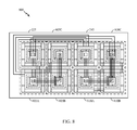
- FIG. 8 depicts an exemplary layout view of the temperature sensor depicted in FIG. 2 .
- FIG. 9 depicts exemplary temperature sensor results.
- FIGS. 10-11 depict different exemplary temperature sensors.
- FIG. 11 depicts an exemplary temperature sensor.
- FIGS. 12A-12B depict a flowcharts of exemplary methods for measuring temperature.
- the temperature sensors have a symmetric bridge-like design including bipolar junction transistors (BJTs) that can have an n-well or a deep n-well isolation structure.
- BJTs bipolar junction transistors
- These new temperature sensors can be used in applications including monitoring in-situ temperature distribution in a silicon chip.
- the temperature sensor disclosed herein advantageously address the long-felt industry needs, as well as other previously unidentified needs, and mitigate shortcomings of the conventional methods and apparatus.
- advantages provided by the disclosed apparatuses and methods include an improvement in signal to noise ratio, an improvement in measurement resolution, an improvement in measurement accuracy, an improvement in measurement reliability over conventional devices, or a combination thereof.
- the term “exemplary” means “serving as an example, instance, or illustration.” Any example described as “exemplary” is not necessarily to be construed as preferred or advantageous over other examples. Likewise, the term “examples of the invention” does not require that all examples of the invention include the discussed feature, advantage, or mode of operation. Use of the terms “in one example,” “an example,” “in one feature,” and/or “a feature” in this specification does not necessarily refer to the same feature and/or example. Furthermore, a particular feature and/or structure can be combined with one or more other features and/or structures. Moreover, at least a portion of the apparatus described hereby can be configured to perform at least a portion of a method described hereby.
- connection means any connection or coupling between elements, either direct or indirect, and can encompass a presence of an intermediate element between two elements that are “connected” or “coupled” together via the intermediate element. Coupling and connection between the elements can be physical, logical, or a combination thereof. Elements can be “connected” or “coupled” together, for example, by using one or more wires, cables, printed electrical connections, electromagnetic energy, and the like.
- the electromagnetic energy can have a wavelength at a radio frequency, a microwave frequency, a visible optical frequency, an invisible optical frequency, and the like.
- signal can include any signal such as a data signal, an audio signal, a video signal, a multimedia signal, an analog signal, a digital signal, and the like.
- Information can be represented using any of a variety of different technologies and techniques. For example, data, an instruction, a process step, a command, information, a signal, a bit, a symbol, and the like can be represented by a voltage, a current, an electromagnetic wave, a magnetic field, a magnetic particle, an optical field, and optical particle, and any combination thereof.
- a reference using a designation such as “first,” “second,” and so forth does not limit either the quantity or the order of those elements. Rather, these designations are used as a convenient method of distinguishing between two or more elements. Thus, a reference to first and second elements does not mean that only two elements can be employed, or that the first element must necessarily precede the second element. Also, unless stated otherwise, a set of elements can comprise one or more elements.
- terminology of the form “at least one of: A, B, or C” used in the description or the claims can be interpreted as “A or B or C or any combination of these elements.”
- this terminology may include A, or B, or C, or A and B, or A and C, or A and B and C, or 2A, or 2B, or 2C, and so on.
- the provided apparatuses can be a part of, and/or coupled to, an electronic device such as, but not limited to, at least one of a mobile device, a navigation device (e.g., a global positioning system receiver), a wireless device, a camera, an audio player, a camcorder, or a game console.
- mobile device can describe, and is not limited to, at least one of a mobile phone, a mobile communication device, a mobile hand-held computer, a portable computer, a tablet computer, a wireless device, a wireless modem, other types of portable electronic devices typically carried by a person and having electro-magnetic communication capabilities, a tablet computer, or any other electronic device that is person-portable.
- UE user equipment
- mobile terminal mobile terminal
- user device mobile device
- wireless device wireless device
- FIG. 1A depicts an exemplary Bipolar Junction Transistor (BJT) temperature sensor 100 .
- the BJT temperature sensor 100 includes a BJT 105 that is diode-connected, that is, the base of BJT 105 is coupled to the collector of BJT 105 .
- the diode-connection configures the BJT 105 into a temperature sensor by causing changes in voltage drops across the BJT 105 to depend upon temperature changes of the BJT 105 .
- base-emitter voltage (V BE ) of the BJT 105 can be determined as follows:
- V BE V G ⁇ ⁇ 0 ⁇ ( 1 - T T 0 ) + V BE ⁇ ⁇ 0 ⁇ ( T T 0 ) + ( nKT q ) ⁇ ln ⁇ ( T 0 T ) + ( KT q ) ⁇ ln ⁇ ( I c I C ⁇ ⁇ 0 ) Equation ⁇ ⁇ One Where, in Equation One:
- Equation Two ( KT q ) ⁇ ln ⁇ ( I C ⁇ ⁇ 1 I C ⁇ ⁇ 2 ) Equation ⁇ ⁇ Two
- FIG. 1B depicts a Brokaw Cell 150 , which is a voltage reference circuit that can also be used as a temperature sensor.
- the Brokaw Cell 150 senses temperature with a pair of transistors (Q 1 , Q 2 ) that have different emitter areas.
- the Brokaw Cell 150 functions as follows.
- a single power supply provides two identical currents (I 1 , I 2 ) through a pair of respective fixed resistors (R).
- a differential amplifier compares the voltages at the respective collectors of transistor Q 1 and transistor Q 2 and feeds back a voltage to the transistors bases that forces two identical currents (I 1 , I 2 ) flow respectively through the emitter of transistor Q 1 and the emitter of transistor Q 2 .
- the respective base-emitter voltages (i.e., the voltage drop) across transistor Q 1 and transistor Q 2 are temperature dependent, as described in Equation One.
- the respective base-emitter voltages (i.e., the voltage drop) across transistor Q 1 and transistor Q 2 are also dissimilar, as the emitter areas of transistor Q 1 and transistor Q 2 are different.
- Transistor Q 2 's emitter current flows through fixed resistor R 2 , while transistor Q 1 's emitter current does not flow through fixed resistor R 2 .
- Transistor Q 2 's emitter current and transistor Q 1 's emitter current combine and flow through fixed resistor R 1 .
- the voltage across R 1 , V PTAT is proportional to absolute temperature (PTAT).
- the V BE of Q 1 is complementary to absolute temperature (CTAT).
- CTAT absolute temperature
- the voltage at the base of Q 1 , V BANDGAP is the sum of V PTAT (PTAT) and V BE of Q 1 (CTAT) and is constant over temperature.
- the Brokaw Cell 150 outputs a proportional to absolute temperature (PTAT) measurement in a form of a voltage (V PTAT ) according to Equation Three:
- V PTAT 2 ⁇ ⁇ R ⁇ ⁇ 1 ⁇ ( V BE - V N )
- R ⁇ ⁇ 2 2 ⁇ ( R ⁇ ⁇ 1 R ⁇ ⁇ 2 ) ⁇ ( kT q ) ⁇ ln ⁇ ( N ) Equation ⁇ ⁇ Three Where, in Equation Three:
- FIG. 2 depicts an exemplary temperature sensor 200 .
- the temperature sensor 200 has NPN BJTs configured in a bridge having a first branch 205 and a second branch 210 .
- the first branch 205 and the second branch 210 are coupled between a first power supply (VDD) 215 and a second power supply (VSS) 220 (e.g., ground).
- the first branch 205 includes a first diode-connected NPN BJT 225 in series with a second diode-connected NPN BJT 230 via first node 235 .
- the first node 235 is a first temperature sensor output.
- the second branch 210 includes a third diode-connected NPN BJT 240 in series with a fourth diode-connected NPN BJT 245 via second node 250 .
- the second node 250 is a second temperature sensor output.
- the first diode-connected NPN BJT 225 in FIG. 2 represents a first number “M 1 ” of diode-connected NPN transistors that is coupled in parallel.
- the fourth diode-connected NPN BJT 245 represents the same number “M 1 ” of diode-connected NPN transistors that is coupled in parallel.
- the second diode-connected NPN BJT 230 in FIG. 2 represents a second number “M 2 ” of diode-connected NPN transistors that is coupled in parallel.
- the third diode-connected NPN BJT 240 represents the same number “M 2 ” of diode-connected NPN transistors that is coupled in parallel.
- a voltage sensor 255 has an input coupled to the first node 235 and the second node 250 .
- the voltage sensor 255 can include a look-up table and is configured to convert a difference in voltage between the first node 235 and the second node 250 to data indicating a temperature of the temperature sensor 200 .
- the respective V BE for each of the first diode-connected NPN BJT 225 , the second diode-connected NPN BJT 230 , the third diode-connected NPN BJT 240 , and the fourth diode-connected NPN BJT 245 varies with temperature.
- the temperature-dependent voltage measured by the voltage sensor 255 between the first node 235 and the second node 250 is proportional to absolute temperature of the devices and is according to Equation Four:
- FIG. 3 depicts an exemplary temperature sensor 300 .
- the temperature sensor 300 has PNP BJTs configured in a bridge having a first branch 305 and a second branch 310 .
- the first branch 305 and the second branch 310 are coupled between a first power supply (VDD) 315 and a second power supply (VSS) 320 (e.g., ground).
- the first branch 305 includes a first diode-connected PNP BJT 325 in series with a second diode-connected PNP BJT 330 via first node 335 .
- the first node 335 is a first temperature sensor output.
- the second branch 310 includes a third diode-connected PNP BJT 340 in series with a fourth diode-connected PNP BJT 345 via second node 350 .
- the second node 350 is a second temperature sensor output.
- the first diode-connected PNP BJT 325 in FIG. 3 represents a first number “M 1 ” of diode-connected PNP transistors that is coupled in parallel.
- the fourth diode-connected PNP BJT 345 represents the same number “M 1 ” of diode-connected PNP transistors that is coupled in parallel.
- the second diode-connected PNP BJT 330 in FIG. 3 represents a second number “M 2 ” of diode-connected PNP transistors that is coupled in parallel.
- the third diode-connected PNP BJT 340 represents the same number “M 2 ” of diode-connected PNP transistors that is coupled in parallel.
- a voltage sensor 355 has an input coupled to the first node 335 and the second node 350 .
- the voltage sensor 355 can include a look-up table and is configured to convert a difference in voltage between the first node 335 and the second node 350 to data indicating a temperature of the temperature sensor 300 .
- At least one of the first diode-connected PNP BJT 325 , the second diode-connected PNP BJT 330 , the third diode-connected PNP BJT 340 , or the fourth diode-connected PNP BJT 345 can have an n-well isolation structure (e.g., 360 , 365 ).
- the n-well isolation structure is at least a part of an isolation region that isolates a collector of a respective transistor to minimize leakage current through a substrate on which the transistor is formed.
- the n-well isolation structure is a deep n-well isolation structure (DNW). Using a deep n-well structure improves sensor accuracy by reducing leakage current.
- the respective V BE for each of the first diode-connected PNP BJT 325 , the second diode-connected PNP BJT 330 , the third diode-connected PNP BJT 340 , and the fourth diode-connected PNP BJT 345 varies with temperature.
- the temperature-dependent voltage measured by the voltage sensor 355 between the first node 335 and the second node 350 is proportional to absolute temperature of the devices and is according to Equation Five:
- Equation Five Equation Five:
- FIG. 4 depicts an exemplary temperature sensor 400 .
- the temperature sensor 400 has PNP BJTs configured in a first branch 405 and a second branch 410 , and can be used when a fabrication process does not support n-well fabrication.
- the first branch 405 and the second branch 410 are coupled between a first power supply (VDD) 415 and a second power supply (VSS) 420 (e.g., ground).
- the first branch 405 includes a first PNP BJT 425 and a second diode-connected PNP BJT 430 via first node 435 .
- the first node 435 is a first temperature sensor output.
- the second branch 410 includes a third PNP BJT 440 in series with a fourth diode-connected PNP BJT 445 via second node 450 .
- the second node 450 is a second temperature sensor output.
- the first PNP BJT 425 in FIG. 4 represents a first number “M 1 ” of diode-connected PNP transistors that is coupled in parallel.
- the fourth diode-connected PNP BJT 445 represents the same number “M 1 ” of diode-connected PNP transistors that is coupled in parallel.
- the second diode-connected PNP BJT 430 in FIG. 4 represents a second number “M 2 ” of diode-connected PNP transistors that is coupled in parallel.
- the third PNP BJT 440 represents the same number “M 2 ” of diode-connected PNP transistors that is coupled in parallel.
- a voltage sensor 455 has an input coupled to the first node 435 and the second node 450 .
- the voltage sensor 455 can include a look-up table and is configured to convert a difference in voltage between the first node 435 and the second node 450 to data indicating a temperature of the temperature sensor 400 .
- the respective V BE for each of the second diode-connected PNP BJT 430 and the fourth diode-connected PNP BJT 445 varies with temperature.
- the voltage measured by the voltage sensor 455 between the first node 435 and the second node 450 provides an output indicative of the temperature of the second diode-connected PNP BJT 430 and the fourth diode-connected PNP BJT 445 .
- FIG. 5 depicts an exemplary temperature sensor 500 .
- the temperature sensor 500 has NPN BJTs configured in a bridge having a first branch 505 and a second branch 510 .
- the first branch 505 and the second branch 510 are coupled between a first power supply (VDD) 515 and a second power supply (VSS) 520 (e.g., ground).
- the first branch 505 includes a first diode-connected NPN BJT 525 in series with a second diode-connected NPN BJT 530 via first node 535 .
- the first node 535 is a first temperature sensor output.
- the second branch 510 includes a third diode-connected NPN BJT 540 in series with a fourth diode-connected NPN BJT 545 via second node 550 .
- the second node 550 is a second temperature sensor output.
- the first diode-connected NPN BJT 525 in FIG. 5 represents a first number “M 1 ” of diode-connected NPN transistors that is coupled in parallel.
- the fourth diode-connected NPN BJT 545 represents the same number “M 1 ” of diode-connected NPN transistors that is coupled in parallel.
- the second diode-connected NPN BJT 530 in FIG. 5 represents a second number “M 2 ” of diode-connected NPN transistors that is coupled in parallel.
- the third diode-connected NPN BJT 540 represents the same number “M 2 ” of diode-connected NPN transistors that is coupled in parallel.
- a voltage sensor 555 has an input coupled to the first node 535 and the second node 550 .
- the voltage sensor 555 can include a look-up table and is configured to convert a difference in voltage between the first node 535 and the second node 550 to data indicating a temperature of the temperature sensor 500 .
- the temperature sensor 500 also has a third power supply (V 3 ) 570 , a fourth power supply (V 4 ) 575 , a first resistor 580 , and a second resistor 585 in a current-divider configuration.
- the resistors can be used to measure the currents that flow through each of the first branch 505 and the second branch 510 to verify the circuit is operating correctly.
- currents having substantially-equivalent magnitudes flow through the first branch 505 and the second branch 510 .
- the respective V BE for each of the first diode-connected NPN BJT 525 , the second diode-connected NPN BJT 530 , the third diode-connected NPN BJT 540 , and the fourth diode-connected NPN BJT 545 varies with temperature.
- the temperature-dependent voltage measured by the voltage sensor 555 between the first node 535 and the second node 550 is proportional to absolute temperature of the devices and is according to Equation Six:
- Equation Six Equation Six:
- FIG. 6 depicts an exemplary temperature sensor 600 .
- the temperature sensor 600 has PNP BJTs configured in a bridge having a first branch 605 and a second branch 610 .
- the first branch 605 and the second branch 610 are coupled between a first power supply (VDD) 615 and a second power supply (VSS) 620 (e.g., ground).
- the first branch 605 includes a first diode-connected PNP BJT 625 in series with a second diode-connected PNP BJT 630 via first node 635 .
- the first node 635 is a first temperature sensor output.
- the second branch 610 includes a third diode-connected PNP BJT 640 in series with a fourth diode-connected PNP BJT 645 via second node 650 .
- the second node 650 is a second temperature sensor output.
- the first diode-connected PNP BJT 625 in FIG. 6 represents a first number “M 1 ” of diode-connected PNP transistors that is coupled in parallel.
- the fourth diode-connected PNP BJT 645 represents the same number “M 1 ” of diode-connected PNP transistors that is coupled in parallel.
- the second diode-connected PNP BJT 630 in FIG. 6 represents a second number “M 2 ” of diode-connected PNP transistors that is coupled in parallel.
- the third diode-connected PNP BJT 640 represents the same number “M 2 ” of diode-connected PNP transistors that is coupled in parallel.
- a voltage sensor 655 has an input coupled to the first node 635 and the second node 650 .
- the voltage sensor 655 can include a look-up table and is configured to convert a difference in voltage between the first node 635 and the second node 650 to data indicating a temperature of the temperature sensor 600 .
- At least one of the first diode-connected PNP BJT 625 , the second diode-connected PNP BJT 630 , the third diode-connected PNP BJT 640 , or the fourth diode-connected PNP BJT 645 can have an n-well isolation structure (e.g., 660 , 665 ).
- the n-well isolation structure is at least a part of an isolation region that isolates a collector of a respective transistor to minimize leakage current through a substrate on which the transistor is formed.
- the n-well isolation structure is a deep n-well isolation structure (DNW). Using a deep n-well structure improves sensor accuracy by reducing leakage current.
- the temperature sensor 600 also has a third power supply (V 3 ) 670 , a fourth power supply (V 4 ) 675 , a first resistor 680 , and a second resistor 685 in a current-divider configuration.
- the resistors can be used to measure the currents that flow through each of the first branch 605 and the second branch 610 to verify the circuit is operating correctly.
- currents having substantially-equivalent magnitudes flow through the first branch 605 and the second branch 610 .
- the respective V BE for each of the first diode-connected PNP BJT 625 , the second diode-connected PNP BJT 630 , the third diode-connected PNP BJT 640 , and the fourth diode-connected PNP BJT 645 varies with temperature.
- the temperature-dependent voltage measured by the voltage sensor 655 between the first node 635 and the second node 650 is proportional to absolute temperature of the devices and is according to Equation Seven:
- Equation Seven Equation Seven:
- FIG. 7 depicts an exemplary temperature sensor 700 .
- the temperature sensor 700 has PNP BJTs configured in a first branch 705 and a second branch 710 , and can be used when a fabrication process does not support n-well fabrication.
- the first branch 705 and the second branch 710 are coupled between a first power supply (VDD) 715 and a second power supply (VSS) 720 (e.g., ground).
- the first branch 705 includes a first PNP BJT 725 and a second diode-connected PNP BJT 730 via first node 735 .
- the first node 735 is a first temperature sensor output.
- the second branch 710 includes a third PNP BJT 740 in series with a fourth diode-connected PNP BJT 745 via second node 750 .
- the second node 750 is a second temperature sensor output.
- the first PNP BJT 725 in FIG. 7 represents a first number “M 1 ” of diode-connected PNP transistors that is coupled in parallel.
- the fourth diode-connected PNP BJT 745 represents the same number “M 1 ” of diode-connected PNP transistors that is coupled in parallel.
- the second diode-connected PNP BJT 730 in FIG. 7 represents a second number “M 2 ” of diode-connected PNP transistors that is coupled in parallel.
- the third PNP BJT 740 represents the same number “M 2 ” of diode-connected PNP transistors that is coupled in parallel.
- a voltage sensor 755 has an input coupled to the first node 735 and the second node 750 .
- the voltage sensor 755 can include a look-up table and is configured to convert a difference in voltage between the first node 735 and the second node 750 to data indicating a temperature of the temperature sensor 700 .
- the temperature sensor 700 also has a third power supply (V 3 ) 770 , a fourth power supply (V 4 ) 775 , a first resistor 780 , and a second resistor 785 in a current-divider configuration.
- the resistors can be used to measure the currents that flow through each of the first branch 705 and the second branch 710 to verify the circuit is operating correctly.
- currents having substantially-equivalent magnitudes flow through the first branch 705 and the second branch 710 .
- the respective V BE for each of the second diode-connected PNP BJT 730 and the fourth diode-connected PNP BJT 745 varies with temperature.
- the voltage measured by the voltage sensor 755 between the first node 735 and the second node 750 provides an output indicative of the temperature of the second diode-connected PNP BJT 730 and the fourth diode-connected PNP BJT 745 .
- FIG. 8 depicts an exemplary layout view 800 of the temperature sensor 200 , where the first branch 205 is depicted in the left half of the layout view 800 , and the second branch 210 is depicted in the right half of the layout view 800 .
- the first diode-connected NPN BJT 225 is depicted in the upper left of the layout view 800 and the fourth diode-connected NPN BJT 245 is depicted as the transistor in the upper row, second from the right side of the layout view 800 .
- the first group is depicted in the layout view 800 as the bottom two transistors in the left half of FIG. 8 , as well as the transistor in the upper row, second from the left.
- the second group is depicted in the layout view 800 as the bottom two transistors in the right half of FIG. 8 , as well as the transistor in the upper right corner.
- FIG. 9 depicts exemplary temperature sensor results 900 .
- the results 900 depict that an example sensor, such as that depicted in FIG. 8 and described with reference to FIG. 2 , can detect temperature-induced changes in V BE as small as 0.03 volts.
- FIG. 10 depicts an exemplary temperature sensor 1000 .
- the temperature sensor 1000 has a voltage-divider configuration including a single branch 1005 coupled between a first power supply (V 2 ) 1010 and a second power supply (V SS ) 1015 (e.g., ground).
- the temperature sensor 1000 also has a current-regulating resistor 1020 coupled between a third power supply (V DD ) 1025 and the first power supply (V 2 ) 1010 .
- the single branch 1005 includes a first diode-connected NPN BJT 1030 in series with a second diode-connected NPN BJT 1035 via node 1040 .
- the node 1040 is a first temperature sensor output (V 1 ).
- the first power supply (V 2 ) 1010 is a second temperature sensor output.
- a voltage sensor 1050 has an input coupled to the node 1040 , the first power supply (V 2 ) 1010 , and the second power supply (V SS ) 1015 .
- the voltage sensor 1050 can include a look-up table and is configured to convert a difference in voltages (e.g., a difference between V BEQ1 and V BEQ2 ) to data indicating a temperature of the temperature sensor 1000 .
- the voltage sensor 1050 is configured to use these voltage measurements as inputs when performing a calculation according to Equation Eight and/or Equation Nine below.
- the first diode-connected NPN BJT 1030 in FIG. 10 represents a first number “M 1 ” of diode-connected NPN transistors that is coupled in parallel.
- M 1 a first number of diode-connected NPN transistors that is coupled in parallel.
- Using a multiple number “M 1 ” of diode-coupled transistors coupled in parallel increases temperature sensor sensitivity by increasing the effect of a temperature change on the combined total change in V BE across the entirety of the parallel-coupled transistors.
- the second diode-connected NPN BJT 1035 in FIG. 10 represents a second number “M 2 ” of diode-connected NPN transistors that is coupled in parallel.
- M 2 the second number of diode-connected NPN transistors that is coupled in parallel.
- Equation Eight The temperature-dependent voltage measured by the voltage sensor 1050 between the node 1040 and the second power supply (V SS ) 1015 is according to Equation Eight:
- FIG. 11 depicts an exemplary temperature sensor 1100 .
- the temperature sensor 1100 has a voltage-divider configuration including a single branch 1105 coupled between a first power supply (V 2 ) 1110 and a second power supply (V SS ) 1115 (e.g., ground).
- the temperature sensor 1100 also has a current-regulating resistor 1120 coupled between a third power supply (V DD ) 1125 and the first power supply (V 2 ) 1110 .
- the single branch 1105 includes a first diode-connected PNP BJT 1130 in series with a second diode-connected PNP BJT 1135 via node 1140 .
- the node 1140 is a first temperature sensor output (V 1 ).
- the second power supply (V SS ) 1115 e.g., ground
- V 0 second temperature sensor output
- a voltage sensor 1150 has an input coupled to the node 1140 , the first power supply (V 2 ) 1110 , and the second power supply (V SS ) 1115 .
- the voltage sensor 1150 can include a look-up table and is configured to convert a difference in voltages (e.g., a difference between V BEQ1 and V BEQ2 ) to data indicating a temperature of the temperature sensor 1100 .
- the voltage sensor 1150 is configured to use these voltage measurements as inputs when performing a calculation according to Equation Ten and/or Equation Eleven below.
- the first diode-connected PNP BJT 1130 in FIG. 11 represents a first number “M 1 ” of diode-connected PNP transistors that is coupled in parallel.
- M 1 a first number of diode-connected PNP transistors that is coupled in parallel.
- the second diode-connected PNP BJT 1135 in FIG. 11 represents a second number “M 2 ” of diode-connected PNP transistors that is coupled in parallel.
- M 2 the second number of diode-connected PNP transistors that is coupled in parallel.
- At least one of the first diode-connected PNP BJT 1130 and the second diode-connected PNP BJT 1135 can have an n-well isolation structure 1155 .
- the n-well isolation structure 1155 is at least a part of an isolation region that isolates a collector of a respective transistor to minimize leakage current through a substrate on which the transistor is formed.
- the n-well isolation structure is a deep n-well isolation structure (DNW). Using a deep n-well structure improves sensor accuracy by reducing leakage current.
- a current flows through the single branch 1105 .
- the respective V BE for each of the first diode-connected PNP BJT 1130 and the second diode-connected PNP BJT 1135 varies with temperature.
- the temperature-dependent voltage measured by the voltage sensor 1150 between the node 1140 and the second power supply (V SS ) 1115 is according to Equation Ten:
- Equation Eleven ( KT Q ) * ln ⁇ ( I C ⁇ ⁇ 1 I C ⁇ ⁇ 2 ) Equation ⁇ ⁇ Eleven
- FIG. 12A depicts a flowchart of an exemplary method for measuring temperature 1200 .
- the method for measuring temperature 1200 can be performed by the apparatus described hereby.
- a first current is caused to flow through a first transistor that is series-coupled with a second transistor via a first node to cause a first voltage drop that is a function of temperature of the first transistor and a second voltage drop that is a function of temperature of the second transistor.
- the first and second transistors are diode-connected.
- an n-well structure or a deep n-well structure can be used to isolate a respective collector of at least one of the first through fourth transistors.
- a second current that is equal in magnitude to the first current is caused to flow through a third transistor that is series-coupled with a fourth transistor via a second node to cause a third voltage drop that is a function of temperature of the third transistor and a fourth voltage drop that is a function of temperature of the fourth transistor.
- the first through fourth transistors are diode-connected.
- an n-well structure or a deep n-well structure can be used to isolate a respective collector of at least one of the first through fourth transistors.
- a fifth voltage drop can be developed across a first number “M 1 ” of diode-connected transistors coupled in parallel between the third transistor and the second node.
- the fifth voltage drop is a function of temperature of the first number “M 1 ” of diode-connected transistors. Further, a sixth voltage drop can be developed across a second number “M 2 ” of diode-connected transistors coupled in parallel between the first node and the second transistor. The sixth voltage drop is a function of temperature of the second number “M 2 ” of diode-connected transistors.
- the magnitude of the first current can be matched with the magnitude of the second current by causing a matching current to flow via at least one of: (1) a first resistor coupled between the power supply and, via a third node, the first transistor, (2) a second power supply coupled to the third node, (3) a second resistor coupled between the power supply and, via a fourth node, the first transistor, or (4) a third power supply coupled to the fourth node.
- a voltage difference between the first node and the second node is measured.
- a look-up table is used to convert the voltage difference to data indicating a temperature of the temperature sensor.
- FIG. 12B depicts a flowchart of an exemplary method for measuring temperature 1250 .
- the method for measuring temperature 1250 can be performed by the apparatus described hereby.
- a first current is caused to flow through a first transistor that is series-coupled with a second transistor via a first node to cause a first voltage drop that is a function of temperature of the first transistor and a second voltage drop that is a function of temperature of the second transistor.
- the first and second transistors are diode-connected.
- an n-well structure or a deep n-well structure can be used to isolate a respective collector of at least one of the first through fourth transistors.
- a base-emitter voltage across the first transistor is measured.
- a base-emitter voltage across the second transistor is measured.
- a differential voltage between the base-emitter voltage across the first transistor and the base-emitter voltage across the second transistor is calculated.
- a look-up table is used to convert the differential voltage to data indicating a temperature of the temperature sensor.
- the disclosed devices and methods can be designed and can be configured into a computer-executable file that is in a Graphic Database System Two (GDSII) compatible format, an Open Artwork System Interchange Standard (OASIS) compatible format, and/or a GERBER (e.g., RS-274D, RS-274X, etc.) compatible format, which are stored on a non-transitory (i.e., a non-transient) computer-readable media.
- GDSII Graphic Database System Two
- OASIS Open Artwork System Interchange Standard
- GERBER e.g., RS-274D, RS-274X, etc.
- the file can be provided to a fabrication handler who fabricates with a lithographic device, based on the file, an integrated device.
- Deposition of a material to form at least a portion of a structure described herein can be performed using deposition techniques such as physical vapor deposition (PVD, e.g., sputtering), plasma-enhanced chemical vapor deposition (PECVD), thermal chemical vapor deposition (thermal CVD), and/or spin-coating.
- Etching of a material to form at least a portion of a structure described herein can be performed using etching techniques such as plasma etching.
- the integrated device is on a semiconductor wafer.
- the semiconductor wafer can be cut into a semiconductor die and packaged into a semiconductor chip.
- the semiconductor chip can be employed in a device described herein (e.g., a mobile device).
Landscapes
- Physics & Mathematics (AREA)
- General Physics & Mathematics (AREA)
- Chemical & Material Sciences (AREA)
- Crystallography & Structural Chemistry (AREA)
- Measuring Temperature Or Quantity Of Heat (AREA)
- Semiconductor Integrated Circuits (AREA)
Abstract
Description
Where, in Equation One:
- VBE=base-emitter voltage
- VG0=extrapolated energy band gap voltage at absolute zero
- T=absolute temperature (in Kelvin)
- T0=reference temperature (in Kelvin)
- VBE0=base-emitter voltage at T0 and IC0
- n=slope factor
- K=Boltzmann's constant
- q=charge of an electron
- Ic=collector current at temperature T
- IC0=reverse saturation current at temperature T0
Thus, absolute temperature can be measured by measuring and comparing band gap voltages at two different currents (IC1 and IC2), after eliminating some variables in Equation One:
Where, in Equation Two:
- ΔVBE=VBE1−VBE2=difference in base-emitter voltage
- VBE1=base-emitter voltage with collector current IC1
- VBE2=base-emitter voltage with collector current IC2
- IC1=first collector current
- IC2=second collector current
Therefore, temperature T can be obtained by measuring ΔVBE:
In general, as temperature of the
Where, in Equation Three:
- VPTAT=voltage across R1 that is proportional to absolute temperature
- R1=resistance of resistor R1 (See
FIG. 1B ) - R2=resistance of resistor R2
- VBE=base-emitter voltage (in the case of
FIG. 1B , the voltage across Q1's base-emitter) - Vn=base-emitter voltage (in the case of
FIG. 1B , the voltage across Q2's base-emitter) - T=absolute temperature (in Kelvin)
- k=Boltzmann's constant
- q=charge of an electron
- N=emitter-to-area ratio (i.e., N:1) of Q1 and Q2
The respective VBE for each of Q1 and Q1 has a negative temperature coefficient. However, due to the configuration of theBrokaw Cell 150, the ΔVBE [=VBE−Vn=VPTAT*R2/(2*R1)] has a positive temperature coefficient.
Where, in Equation Four:
- Voltage=voltage measured by the
voltage sensor 255 - VBEQ2=VBE of the second diode-connected
NPN BJT 230 at the specific absolute temperature=voltage atnode 235 - VBEQ4=VBE of the fourth diode-connected
NPN BJT 245 at the specific absolute temperature=voltage atnode 250
Where, in Equation Five:
- Voltage=voltage measured by the
voltage sensor 355 - VBEQ2=VBE of the second diode-connected
PNP BJT 330 at the specific absolute temperature=voltage atnode 335 - VBEQ4=VBE of the fourth diode-connected
PNP BJT 345 at the specific absolute temperature=voltage atnode 350
Where, in Equation Six:
- Voltage=voltage measured by the
voltage sensor 555 - VBEQ2=VBE of the second diode-connected
NPN BJT 530 at the specific absolute temperature - VBEQ4=VBE of the fourth diode-connected
NPN BJT 545 at the specific absolute temperature
Where, in Equation Seven:
- Voltage=voltage measured by the
voltage sensor 655 - VBEQ2=VBE of the second diode-connected
PNP BJT 630 at the specific absolute temperature - VBEQ4=VBE of the fourth diode-connected PNP BJT 645 at the specific absolute temperature
Where, in Equation Eight:
- Voltage=voltage measured by the voltage sensor 1050
- VBEQ1=VBE of the first diode-connected
NPN BJT 1030 at a specific absolute temperature - VBEQ2=VBE of the second diode-connected NPN BJT 1035 at the specific absolute temperature
Further, ΔVBE=VBEQ1−VBEQ2 can be determined by Equation Nine:
Where, in Equation Nine:
- IC1=the total current through the first diode-connected
NPN BJT 1030 divided by the multiplier M1 - IC2=the total current through the second diode-connected NPN BJT 1035 divided by the multiplier M2
- IC1 and IC2 are unit currents through a single transistor without a multiplier.
Where, in Equation Ten:
- Voltage=voltage measured by the
voltage sensor 1150 - VBEQ1=VBE of the first diode-connected
PNP BJT 1130 at a specific absolute temperature - VBEQ2=VBE of the second diode-connected
PNP BJT 1135 at the specific absolute temperature
Further, ΔVBE can be determined by Equation Eleven:
Where, in Equation Eleven:
- IC1=the total current through the first diode-connected
NPN BJT 1030 divided by the multiplier M1 - IC2=the total current through the second diode-connected NPN BJT 1035 divided by the multiplier M2
- IC1 and IC2 are unit currents through a single transistor without a multiplier.
Claims (38)
Priority Applications (2)
| Application Number | Priority Date | Filing Date | Title |
|---|---|---|---|
| US14/639,053 US9970826B2 (en) | 2015-03-04 | 2015-03-04 | Bipolar junction transistor voltage-drop-based temperature sensors |
| PCT/US2016/017072 WO2016140776A1 (en) | 2015-03-04 | 2016-02-09 | Bipolar junction transistor-based temperature sensors |
Applications Claiming Priority (1)
| Application Number | Priority Date | Filing Date | Title |
|---|---|---|---|
| US14/639,053 US9970826B2 (en) | 2015-03-04 | 2015-03-04 | Bipolar junction transistor voltage-drop-based temperature sensors |
Publications (2)
| Publication Number | Publication Date |
|---|---|
| US20160258819A1 US20160258819A1 (en) | 2016-09-08 |
| US9970826B2 true US9970826B2 (en) | 2018-05-15 |
Family
ID=55359773
Family Applications (1)
| Application Number | Title | Priority Date | Filing Date |
|---|---|---|---|
| US14/639,053 Active 2036-05-21 US9970826B2 (en) | 2015-03-04 | 2015-03-04 | Bipolar junction transistor voltage-drop-based temperature sensors |
Country Status (2)
| Country | Link |
|---|---|
| US (1) | US9970826B2 (en) |
| WO (1) | WO2016140776A1 (en) |
Cited By (3)
| Publication number | Priority date | Publication date | Assignee | Title |
|---|---|---|---|---|
| US20190086272A1 (en) * | 2017-09-17 | 2019-03-21 | Qualcomm Incorporated | Diode-based temperature sensor |
| US11493389B2 (en) * | 2018-09-28 | 2022-11-08 | Taiwan Semiconductor Manufacturing Company, Ltd. | Low temperature error thermal sensor |
| US20220364936A1 (en) * | 2018-09-28 | 2022-11-17 | Taiwan Semiconductor Manufacturing Company, Ltd. | Low temperature error thermal sensor |
Families Citing this family (4)
| Publication number | Priority date | Publication date | Assignee | Title |
|---|---|---|---|---|
| US9816872B2 (en) * | 2014-06-09 | 2017-11-14 | Qualcomm Incorporated | Low power low cost temperature sensor |
| US9780736B1 (en) * | 2016-03-30 | 2017-10-03 | Synaptics Incorporated | Temperature compensated offset cancellation for high-speed amplifiers |
| EP3514653B1 (en) * | 2018-01-19 | 2022-06-08 | Socionext Inc. | Signal-generation circuitry |
| US11280682B2 (en) * | 2019-09-04 | 2022-03-22 | Nxp Usa, Inc. | Temperature sensor circuit |
Citations (17)
| Publication number | Priority date | Publication date | Assignee | Title |
|---|---|---|---|---|
| US4004462A (en) * | 1974-06-07 | 1977-01-25 | National Semiconductor Corporation | Temperature transducer |
| US4243898A (en) | 1978-11-16 | 1981-01-06 | Motorola, Inc. | Semiconductor temperature sensor |
| US5546041A (en) * | 1993-08-05 | 1996-08-13 | Massachusetts Institute Of Technology | Feedback sensor circuit |
| US6060792A (en) | 1997-05-20 | 2000-05-09 | International Rectifier Corp. | Instantaneous junction temperature detection |
| US6149299A (en) | 1997-12-11 | 2000-11-21 | National Semiconductor Corporation | Direct temperature sensing of a semiconductor device semiconductor device |
| US20030067344A1 (en) * | 2001-10-09 | 2003-04-10 | Fujitsu Limited | Semiconductor device with temperature compensation circuit |
| US20050264971A1 (en) * | 2004-06-01 | 2005-12-01 | Koichi Morino | Semiconductor integrated circuit apparatus having overheat protection circuit and overheat protection method |
| US6995588B2 (en) * | 2003-04-30 | 2006-02-07 | Agilent Technologies, Inc. | Temperature sensor apparatus |
| US7281846B2 (en) * | 2004-08-23 | 2007-10-16 | Standard Microsystems Corporation | Integrated resistance cancellation in temperature measurement systems |
| US20080018482A1 (en) | 2006-07-11 | 2008-01-24 | Chi-Kun Chiu | Temperature sensing apparatus utilizing bipolar junction transistor, and related method |
| US7841770B2 (en) | 2008-05-29 | 2010-11-30 | Hycon Technology Corp. | Temperature measuring system and measuring method using the same |
| US8136987B2 (en) * | 2008-12-31 | 2012-03-20 | Intel Corporation | Ratio meter for temperature sensor |
| US8217708B2 (en) | 2008-11-14 | 2012-07-10 | Seiko Instruments Inc. | Temperature sensor |
| US8378735B2 (en) | 2010-11-29 | 2013-02-19 | Freescale Semiconductor, Inc. | Die temperature sensor circuit |
| US20140184311A1 (en) * | 2012-12-28 | 2014-07-03 | Kabushiki Kaisha Toshiba | Temperature detecting circuit, temperature compensating circuit, and buffer circuit |
| US20150063419A1 (en) * | 2013-09-02 | 2015-03-05 | Renesas Electronics Corporation | Signal generation circuit and temperature sensor |
| US20160116345A1 (en) * | 2014-10-28 | 2016-04-28 | Infineon Technologies Austria Ag | System and Method for Temperature Sensing |
-
2015
- 2015-03-04 US US14/639,053 patent/US9970826B2/en active Active
-
2016
- 2016-02-09 WO PCT/US2016/017072 patent/WO2016140776A1/en not_active Ceased
Patent Citations (17)
| Publication number | Priority date | Publication date | Assignee | Title |
|---|---|---|---|---|
| US4004462A (en) * | 1974-06-07 | 1977-01-25 | National Semiconductor Corporation | Temperature transducer |
| US4243898A (en) | 1978-11-16 | 1981-01-06 | Motorola, Inc. | Semiconductor temperature sensor |
| US5546041A (en) * | 1993-08-05 | 1996-08-13 | Massachusetts Institute Of Technology | Feedback sensor circuit |
| US6060792A (en) | 1997-05-20 | 2000-05-09 | International Rectifier Corp. | Instantaneous junction temperature detection |
| US6149299A (en) | 1997-12-11 | 2000-11-21 | National Semiconductor Corporation | Direct temperature sensing of a semiconductor device semiconductor device |
| US20030067344A1 (en) * | 2001-10-09 | 2003-04-10 | Fujitsu Limited | Semiconductor device with temperature compensation circuit |
| US6995588B2 (en) * | 2003-04-30 | 2006-02-07 | Agilent Technologies, Inc. | Temperature sensor apparatus |
| US20050264971A1 (en) * | 2004-06-01 | 2005-12-01 | Koichi Morino | Semiconductor integrated circuit apparatus having overheat protection circuit and overheat protection method |
| US7281846B2 (en) * | 2004-08-23 | 2007-10-16 | Standard Microsystems Corporation | Integrated resistance cancellation in temperature measurement systems |
| US20080018482A1 (en) | 2006-07-11 | 2008-01-24 | Chi-Kun Chiu | Temperature sensing apparatus utilizing bipolar junction transistor, and related method |
| US7841770B2 (en) | 2008-05-29 | 2010-11-30 | Hycon Technology Corp. | Temperature measuring system and measuring method using the same |
| US8217708B2 (en) | 2008-11-14 | 2012-07-10 | Seiko Instruments Inc. | Temperature sensor |
| US8136987B2 (en) * | 2008-12-31 | 2012-03-20 | Intel Corporation | Ratio meter for temperature sensor |
| US8378735B2 (en) | 2010-11-29 | 2013-02-19 | Freescale Semiconductor, Inc. | Die temperature sensor circuit |
| US20140184311A1 (en) * | 2012-12-28 | 2014-07-03 | Kabushiki Kaisha Toshiba | Temperature detecting circuit, temperature compensating circuit, and buffer circuit |
| US20150063419A1 (en) * | 2013-09-02 | 2015-03-05 | Renesas Electronics Corporation | Signal generation circuit and temperature sensor |
| US20160116345A1 (en) * | 2014-10-28 | 2016-04-28 | Infineon Technologies Austria Ag | System and Method for Temperature Sensing |
Non-Patent Citations (3)
| Title |
|---|
| Abu-Zeid M M., et al., "Diode-bridge Temperature Sensor", Review of Scientific Instruments, AIP, Melville, NY, US, vol. 57, No. 10, Oct. 1, 1986 (Oct. 1, 1986), pp. 2609-2613, XP001412429, ISSN: 0034-6748 the whole document. |
| International Search Report and Wirtten Opinion—PCT/US2016/017072—ISA/EPO—Apr. 12, 2016. |
| M. M. ABU-ZEID; A. G. SASBURG: "Diode-bridge Temperature sensor", REVIEW OF SCIENTIFIC INSTRUMENTS., AIP, MELVILLE, NY., US, vol. 57, no. 10, 1 October 1986 (1986-10-01), US, pages 2609 - 2613, XP001412429, ISSN: 0034-6748 |
Cited By (4)
| Publication number | Priority date | Publication date | Assignee | Title |
|---|---|---|---|---|
| US20190086272A1 (en) * | 2017-09-17 | 2019-03-21 | Qualcomm Incorporated | Diode-based temperature sensor |
| US10578497B2 (en) * | 2017-09-17 | 2020-03-03 | Qualcomm Incorporated | Diode-based temperature sensor |
| US11493389B2 (en) * | 2018-09-28 | 2022-11-08 | Taiwan Semiconductor Manufacturing Company, Ltd. | Low temperature error thermal sensor |
| US20220364936A1 (en) * | 2018-09-28 | 2022-11-17 | Taiwan Semiconductor Manufacturing Company, Ltd. | Low temperature error thermal sensor |
Also Published As
| Publication number | Publication date |
|---|---|
| WO2016140776A1 (en) | 2016-09-09 |
| US20160258819A1 (en) | 2016-09-08 |
Similar Documents
| Publication | Publication Date | Title |
|---|---|---|
| US9970826B2 (en) | Bipolar junction transistor voltage-drop-based temperature sensors | |
| Sasaki et al. | A Temperature Sensor With an Inaccuracy of ${-}{\hbox {1}}/{+}{\hbox {0.8}}\^{\circ} $ C Using 90-nm 1-V CMOS for Online Thermal Monitoring of VLSI Circuits | |
| US9335223B2 (en) | Circuits and methods for determining the temperature of a transistor | |
| US4123698A (en) | Integrated circuit two terminal temperature transducer | |
| US6987416B2 (en) | Low-voltage curvature-compensated bandgap reference | |
| US6082115A (en) | Temperature regulator circuit and precision voltage reference for integrated circuit | |
| Michejda et al. | A precision CMOS bandgap reference | |
| US9804614B2 (en) | Bandgap reference circuit and method for room temperature trimming with replica elements | |
| US9489000B2 (en) | Use of a thermistor within a reference signal generator | |
| CN107257948A (en) | Calibrated temperature sensing system | |
| CN105974996B (en) | Reference voltage source | |
| CN101349928A (en) | Ultra-low voltage sub-bandgap voltage reference generator | |
| US11086347B1 (en) | Bandgap reference circuit and electronic device | |
| Song et al. | Characterization of bipolar transistors for cryogenic temperature sensors in standard CMOS | |
| CN103197716A (en) | Band-gap reference voltage circuit for reducing offset voltage influence | |
| US20030123520A1 (en) | Temperature detector | |
| US7915947B2 (en) | PTAT sensor and temperature sensing method thereof | |
| US10578497B2 (en) | Diode-based temperature sensor | |
| US20030001660A1 (en) | Temperature-dependent reference generator | |
| US20250130117A1 (en) | Thermal sensor for integrated circuit | |
| CN105574228A (en) | Circuit and method for compensating for early effects | |
| KR20150122911A (en) | CMOS temperature sensor and temperature measuring method of the same | |
| CN114675706A (en) | A bandgap reference core circuit, a bandgap reference source and a semiconductor memory | |
| JP4314669B2 (en) | Bandgap reference circuit | |
| CN104122928A (en) | Band-gap reference voltage generating circuit with low temperature drift coefficient |
Legal Events
| Date | Code | Title | Description |
|---|---|---|---|
| AS | Assignment |
Owner name: QUALCOMM INCORPORATED, CALIFORNIA Free format text: ASSIGNMENT OF ASSIGNORS INTEREST;ASSIGNORS:XIA, WILLIAM;YUEN, KENDRICK HOY LEONG;REEL/FRAME:035281/0145 Effective date: 20150312 |
|
| STCF | Information on status: patent grant |
Free format text: PATENTED CASE |
|
| MAFP | Maintenance fee payment |
Free format text: PAYMENT OF MAINTENANCE FEE, 4TH YEAR, LARGE ENTITY (ORIGINAL EVENT CODE: M1551); ENTITY STATUS OF PATENT OWNER: LARGE ENTITY Year of fee payment: 4 |
|
| FEPP | Fee payment procedure |
Free format text: MAINTENANCE FEE REMINDER MAILED (ORIGINAL EVENT CODE: REM.); ENTITY STATUS OF PATENT OWNER: LARGE ENTITY |