US996800A - Muffler. - Google Patents
Muffler. Download PDFInfo
- Publication number
- US996800A US996800A US51070609A US1909510706A US996800A US 996800 A US996800 A US 996800A US 51070609 A US51070609 A US 51070609A US 1909510706 A US1909510706 A US 1909510706A US 996800 A US996800 A US 996800A
- Authority
- US
- United States
- Prior art keywords
- casing
- head
- tubular member
- gases
- perforations
- Prior art date
- Legal status (The legal status is an assumption and is not a legal conclusion. Google has not performed a legal analysis and makes no representation as to the accuracy of the status listed.)
- Expired - Lifetime
Links
Images
Classifications
-
- F—MECHANICAL ENGINEERING; LIGHTING; HEATING; WEAPONS; BLASTING
- F01—MACHINES OR ENGINES IN GENERAL; ENGINE PLANTS IN GENERAL; STEAM ENGINES
- F01N—GAS-FLOW SILENCERS OR EXHAUST APPARATUS FOR MACHINES OR ENGINES IN GENERAL; GAS-FLOW SILENCERS OR EXHAUST APPARATUS FOR INTERNAL COMBUSTION ENGINES
- F01N1/00—Silencing apparatus characterised by method of silencing
- F01N1/16—Silencing apparatus characterised by method of silencing by using movable parts
- F01N1/166—Silencing apparatus characterised by method of silencing by using movable parts for changing gas flow path through the silencer or for adjusting the dimensions of a chamber or a pipe
Definitions
- This invention relates generally to mufiiers for explosive engines and the like, and is particularly applicable to explosive engines used in motor boats and the like.
- the invention relates to a cylindrical casing provided with an outlet at one end and an opening at the other adapted to permit the insertion ot a series ot tubular bathing members mounted in a head, all arranged in a manner such that the gases are baliied and expanded in a manner to deaden or dissipate the exhaust charge, together with a suitable device for regulating the passage through the mutiier and means for supplying water in manner such that the gases are cooled in their passage through the mutller.
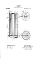
- Figure 1 is i longitudinal sectional view of the muiller
- Fig. 2 is a section upon the line 2-2 of Fig.
- Fig. 3 is an end elevation looking toward the lett in Fig. 1.
- any preferred forni andconstruction of parts may be employed so long as they possess the nocessary features, but I have shown one form in the drawings which is highly efficient in operation, and in such embodiment 1 represents acylindrical. casing open at one end and provided at the other end with a head 2 integral therewithhaving therein a pipe connection 3 for the exhaust. from the mutfler. Adjacent to the head 2 is a boss 11 hav ing an opening 5 therein for a purpose to be described.
- the casing 1 is still further provided near the head 2 with an annular Harige 6 for a purpose to beldescribed.
- the edge of the casing about the open' end thereof is provided with an enlarged portion Z adapt- 'ed to receive the bolts for securing the other head to the casing.
- the right-hand end or the 'open end of the casing, as shownl in the drawings, is provided 'with a removable hea-d 8 having a cenprovided with perforations 13.which are adapted to project the infiowing water in two directions as will later be more fully described.
- This hea d is still further provided with a boss lat to one side of the pipe 12 as shown in Fig. 3, and adapted to receive a rod 15, passing through a stutiing box about the boss 111, having on its outer end a suitable grip 16 and on its inner end a regulating device which will be disclosed later.
- the inner face of the head 8 has an annular flange 17 receiving a tubular member 18 ⁇ provided with numerous perforations 18a adjacent to the head 8, and holding this tubular member in concentric arrangementwith respect to the. casing 1.
- a sleev'e 19 Slidably mounted upon this tubular member 18 is a sleev'e 19 provided witha clip 2O which has a bifurcated end portion 21 secured between nuts 22 and 23 on the rod 15.
- This sleeve may be slid upon the tubular member 18 to expose any desired number of perfo 'ations 18n and to thereby aifect the volume of the exhaust through the muffler.
- the head 8 has another annular flange 2st supporting a smaller tubular me1nber 25 which is provided with pert'orations Q6 at its inner end, and this tube is adapted to receive the exhaust gases from the pipe connection 9 and discharges them through apertures 2G at the inner end oi the tubular member' 18 so that they will pass between the two tubular members and out through the perforations 18a.
- the inner is adapted to receive the exhaust gases from the pipe connection 9 and discharges them through apertures 2G at the inner end oi the tubular member' 18 so that they will pass between the two tubular members and out through the perforations 18a.
- lugs is provided at the center witlifa cast hutten tly valve *trame 31 suitably secured to the' ⁇ diaphragm as by screws or rivets 37 Jand" having an opening 32 at the center thereof and-a Vbossu for receiving the lower end of the valve stem 34 which passes up the exhaust nipple through the opening 5 in the boss 4t and through a stutiing box 35 upon said boss.
- a butterfly valve 36 is mounted upon this stem and may be arranged to clese the opening S2 whereby the gases must pass through the muffler, but when this valve is open, the gases may pass directly through the inner tubular member Q5 and out. through It.
- the operator closes the buttertly valve 36 causing the exhaust gases to pass through the inner tubular member 25 to the perforat'ions QG where they are expanded upon the outside ot the inner tubular member and within the tubular member 18 and must pass to the right end of the muliler where they may discharge through the periiorations 1S which may he regulated in number by the sleeve 19 controlled by the rod l5. ln the meantime water is being discharged trom the pipe l2 around the tubular member 18 by the pertorations 'lil so that the gases are cooled in their passage. iter passing through the openings i8 the gases pass to the le'tt end. as shown in the drawings and through the perfor-ations f3() in the diaphragnrQti from whence they may pass out through the exhaust comieetion 23.
- a mulller in combination, a casing having oie oprn end and closed at; its other end by an integral tixed head, a removable head adapted to be secured to the casing at said open end. and a plurality-ot mulller tubes secured lo and supported at one end by said removable head and provided at their respective opposite ends with perforations arranged in a manner to baille the exhaust in its passage through the mutller. .2.
- a casing having an open cud. u bead tor the open end described invention, lr..
- atubular member secured to such head at one end aud carrying at its other end an inner diaphragm adapted to tit Within the casing, said tubular member being provided with discharge openings near one end, another tubular member mounted between the diaphragm and the outer head and provided with' pertorations at its end opposite to the pertorations of the first mentioned tubular member.
- a mutller in combination, a casing having an open end, a. head adapted to be secured to the casing at its open end, a cylindrical member, an inner tubular member mounted between the firstn'icntioncd. head and the inner head and adapted to receive the exhaust gases, said inner tubular member being provided with perforations near its outer end, and said cylindrical member being provided with perforations adjacent to .the first mentioned head, and a suitable by pass valve located in the inner head and adapted to discharge the gases directly from the inner tubular member.
- a mutller in combination, a casing having an open end, an annular Shoulder Carried by the casing, an outer head for said casing and adapted to be secured to the same at the end thereof, a cylindrical member secured to the outer head, an inner head secured to the outer end of thc cylindrical member, and adapted to take against the annular shoulder within the casing, an inner tubular member mounted between the outer and inner heads, said inner tubular member being provided with perforations adjacent to the inner head, and the cylindrical member being provided with-perfor: tions adjacent to the outer head, and a valve arranged in the inner head and adapted to discharge gases irom the inner tubular mem-' ber.
- a casing in combination, a casing, a tubular member mounted in said casing and provided with pcrforations tor discharging the gases into the casing, and means for varying the number of pertoratious.
- a mutller in combination, a casing, a tubular member mounted in said casing and provided with'perfor-ations tor discharging the gases into the casing, and a sleeve slidably mounted on the cylindrical member for closing the pert'orations therein.
- a mutller in combination, a casing, a tubular member mounted in said casing and provided with perforations tor discharging the gases t'rom the casing, and means t'or varying the number oi perforations left for operation, a sleeve slidably mounted on the cylindrical member tor closing the perforatiions therein, and means tor shitting said sleeve.
- a casing in combination, a casing, tubular battling members Within said casing, and a Water supply pipe extending above said tubular bathing members and provided with openings in two directions for directing streams of water around the periphery of the cylindrical member.
- a easing in combination, a head for said casing, a cylindrical member supported by said head at one end and carrying at its other end an inner head adapted to be supported by the casing, said cylindrical member being provided with discharge openings, an innerA tubular member mounted within the cylindrical member and supported between the two heads and provided with discharge perforations, and a butter-Hy valve located in the inner head for y by passing the exhaust from the inner tubu ⁇ lar member.
- a muflier, 1n combination a casing, a head fo said casing, a cylindrical member supported by said head at one end and ea'r rying at its other end an inner head adapted to be supported by the casing, said cylindrical member being provided with discharge openings, an inner tubular member mounted within the cylindrical member and supported between the two heads and provided with discharge perforations, a butterfly valve located in the inner head for by passing the exhaust from the inner tubular member, and a stem for said valve extending upon the outside'of the casing.
Landscapes
- Engineering & Computer Science (AREA)
- Chemical & Material Sciences (AREA)
- Combustion & Propulsion (AREA)
- Mechanical Engineering (AREA)
- General Engineering & Computer Science (AREA)
- Exhaust Silencers (AREA)
Description
Patented July 4,1911.
J. 0. SCHMITT.'
Y 'MUFFLEIL APPLIOTIO( [LED AUG. 2, v1909.
Zz/M2555 E5 fZUEz-z fr.' y fw/wi jzmr 21575.
, trally located pipe connection 9 and a'rein- JOHN 0. SCHMITT, Olli` CLEVELAND, OHIO.
MUFFLER.l
Specification of Letters Patent.
Patented July i, 1911.
Application filed August 2i, 1909. Serial No. 510,706.
To all whom/it may concern.'
Be itknown that I, JOHN O. Sounirr, a citizen of the United States, residing at Cleveland, in the county ot' Cuyahoga and State of Ohio, have invented certain new and useful Improveuients in hlutllers, ot which the following is a. s peeitication.
This invention relates generally to mufiiers for explosive engines and the like, and is particularly applicable to explosive engines used in motor boats and the like.
More specilically the invention relates to a cylindrical casing provided with an outlet at one end and an opening at the other adapted to permit the insertion ot a series ot tubular bathing members mounted in a head, all arranged in a manner such that the gases are baliied and expanded in a manner to deaden or dissipate the exhaust charge, together with a suitable device for regulating the passage through the mutiier and means for supplying water in manner such that the gases are cooled in their passage through the mutller.
The invention further relates to certain details of construction hereinafter set itorth in the following description, drawings and claims. y
Referring to the drawings, Figure 1 is i longitudinal sectional view of the muiller;4
Fig. 2 is a section upon the line 2-2 of Fig.
'1; and Fig. 3 is an end elevation looking toward the lett in Fig. 1.
In carrying out the invention any preferred forni andconstruction of parts may be employed so long as they possess the nocessary features, but I have shown one form in the drawings which is highly efficient in operation, and in such embodiment 1 represents acylindrical. casing open at one end and provided at the other end with a head 2 integral therewithhaving therein a pipe connection 3 for the exhaust. from the mutfler. Adjacent to the head 2 is a boss 11 hav ing an opening 5 therein for a purpose to be described. The casing 1 is still further provided near the head 2 with an annular Harige 6 for a purpose to beldescribed. The edge of the casing about the open' end thereof is provided with an enlarged portion Z adapt- 'ed to receive the bolts for securing the other head to the casing.
The right-hand end or the 'open end of the casing, as shownl in the drawings, is provided 'with a removable hea-d 8 having a cenprovided with perforations 13.which are adapted to project the infiowing water in two directions as will later be more fully described. This hea d is still further provided with a boss lat to one side of the pipe 12 as shown in Fig. 3, and adapted to receive a rod 15, passing through a stutiing box about the boss 111, having on its outer end a suitable grip 16 and on its inner end a regulating device which will be disclosed later. The inner face of the head 8 has an annular flange 17 receiving a tubular member 18 `provided with numerous perforations 18a adjacent to the head 8, and holding this tubular member in concentric arrangementwith respect to the. casing 1.
Slidably mounted upon this tubular member 18 is a sleev'e 19 provided witha clip 2O which has a bifurcated end portion 21 secured between nuts 22 and 23 on the rod 15. This sleeve may be slid upon the tubular member 18 to expose any desired number of perfo 'ations 18n and to thereby aifect the volume of the exhaust through the muffler. The head 8 has another annular flange 2st supporting a smaller tubular me1nber 25 which is provided with pert'orations Q6 at its inner end, and this tube is adapted to receive the exhaust gases from the pipe connection 9 and discharges them through apertures 2G at the inner end oi the tubular member' 18 so that they will pass between the two tubular members and out through the perforations 18a. The inner. end of the tubular member 18 is provided with lugs is provided at the center witlifa cast hutten tly valve *trame 31 suitably secured to the'` diaphragm as by screws or rivets 37 Jand" having an opening 32 at the center thereof and-a Vbossu for receiving the lower end of the valve stem 34 which passes up the exhaust nipple through the opening 5 in the boss 4t and through a stutiing box 35 upon said boss. A butterfly valve 36 is mounted upon this stem and may be arranged to clese the opening S2 whereby the gases must pass through the muffler, but when this valve is open, the gases may pass directly through the inner tubular member Q5 and out. through It. will be seen 'from the foregoing construction that when the tubular member 1S is secured in the head 8 with the adjusting sleeve 19 and its operating rod arranged in conjunction with it, and with the diaphragm 29 secured to the end of the tubular member 18 by bending over the lugs 27 and the tubular member in place within the same, that the entire internal mechanism with the exception ot the butterfly valve 36 and its stem 34- may be moved into the casing l, and after the screws or bolts 1l are applied the main part ot the mu'lller is assembled. The buttertiy valve 36 and its stem 3ft may then be placed in position. lit is also necessary t secure the pipe 1Q in place before inserting the tubular members in the casing.
In using the mutller the operator closes the buttertly valve 36 causing the exhaust gases to pass through the inner tubular member 25 to the perforat'ions QG where they are expanded upon the outside ot the inner tubular member and within the tubular member 18 and must pass to the right end of the muliler where they may discharge through the periiorations 1S which may he regulated in number by the sleeve 19 controlled by the rod l5. ln the meantime water is being discharged trom the pipe l2 around the tubular member 18 by the pertorations 'lil so that the gases are cooled in their passage. iter passing through the openings i8 the gases pass to the le'tt end. as shown in the drawings and through the perfor-ations f3() in the diaphragnrQti from whence they may pass out through the exhaust comieetion 23.
l do not desire to be continedto the exact details shown but aim in my claims to cover all moditieations which do not. involve a departure from the spirit and scope ot' my invention.
llaving claim :h4
l.. ln a mulller, in combination, a casing having oie oprn end and closed at; its other end by an integral tixed head, a removable head adapted to be secured to the casing at said open end. and a plurality-ot mulller tubes secured lo and supported at one end by said removable head and provided at their respective opposite ends with perforations arranged in a manner to baille the exhaust in its passage through the mutller. .2. In a mutller, in combination, a casing having an open cud. u bead tor the open end described invention, lr..
of said easing, atubular member secured to such head at one end aud carrying at its other end an inner diaphragm adapted to tit Within the casing, said tubular member being provided with discharge openings near one end, another tubular member mounted between the diaphragm and the outer head and provided with' pertorations at its end opposite to the pertorations of the first mentioned tubular member.
3. ln a mutller, in combination, a casing having an open end, a. head adapted to be secured to the casing at its open end, a cylindrical member, an inner tubular member mounted between the firstn'icntioncd. head and the inner head and adapted to receive the exhaust gases, said inner tubular member being provided with perforations near its outer end, and said cylindrical member being provided with perforations adjacent to .the first mentioned head, and a suitable by pass valve located in the inner head and adapted to discharge the gases directly from the inner tubular member.
4;. ln a mutller, in combination, a casing having an open end, an annular Shoulder Carried by the casing, an outer head for said casing and adapted to be secured to the same at the end thereof, a cylindrical member secured to the outer head, an inner head secured to the outer end of thc cylindrical member, and adapted to take against the annular shoulder within the casing, an inner tubular member mounted between the outer and inner heads, said inner tubular member being provided with perforations adjacent to the inner head, and the cylindrical member being provided with-perfor: tions adjacent to the outer head, and a valve arranged in the inner head and adapted to discharge gases irom the inner tubular mem-' ber.
5. In a mnlllcr, in combination, a casing, a tubular member mounted in said casing and provided with pcrforations tor discharging the gases into the casing, and means for varying the number of pertoratious.
(i. Tn a mutller, in combination, a casing, a tubular member mounted in said casing and provided with'perfor-ations tor discharging the gases into the casing, and a sleeve slidably mounted on the cylindrical member for closing the pert'orations therein.
7. ln a mutller, in combination, a casing, a tubular member mounted in said casing and provided with perforations tor discharging the gases t'rom the casing, and means t'or varying the number oi perforations left for operation, a sleeve slidably mounted on the cylindrical member tor closing the perforatiions therein, and means tor shitting said sleeve.
8. In a mutller, in combination, a casing, tubular battling members Within said casing, and a Water supply pipe extending above said tubular bathing members and provided with openings in two directions for directing streams of water around the periphery of the cylindrical member.
9. In a muler, in combination, a easing, a head for said casing, a cylindrical member supported by said head at one end and carrying at its other end an inner head adapted to be supported by the casing, said cylindrical member being provided with discharge openings, an innerA tubular member mounted within the cylindrical member and supported between the two heads and provided with discharge perforations, and a butter-Hy valve located in the inner head for y by passing the exhaust from the inner tubu` lar member.
10. In a muflier, 1n combination, a casing, a head fo said casing, a cylindrical member supported by said head at one end and ea'r rying at its other end an inner head adapted to be supported by the casing, said cylindrical member being provided with discharge openings, an inner tubular member mounted within the cylindrical member and supported between the two heads and provided with discharge perforations, a butterfly valve located in the inner head for by passing the exhaust from the inner tubular member, and a stem for said valve extending upon the outside'of the casing.
In testimony whereof I aflix my signature in presence of two witnesses.
JOHN O. SCHMITT.
Priority Applications (1)
| Application Number | Priority Date | Filing Date | Title |
|---|---|---|---|
| US51070609A US996800A (en) | 1909-08-02 | 1909-08-02 | Muffler. |
Applications Claiming Priority (1)
| Application Number | Priority Date | Filing Date | Title |
|---|---|---|---|
| US51070609A US996800A (en) | 1909-08-02 | 1909-08-02 | Muffler. |
Publications (1)
| Publication Number | Publication Date |
|---|---|
| US996800A true US996800A (en) | 1911-07-04 |
Family
ID=3065131
Family Applications (1)
| Application Number | Title | Priority Date | Filing Date |
|---|---|---|---|
| US51070609A Expired - Lifetime US996800A (en) | 1909-08-02 | 1909-08-02 | Muffler. |
Country Status (1)
| Country | Link |
|---|---|
| US (1) | US996800A (en) |
Cited By (1)
| Publication number | Priority date | Publication date | Assignee | Title |
|---|---|---|---|---|
| US20070012510A1 (en) * | 2005-07-18 | 2007-01-18 | Roland Kess | Muffler outlet part for a motorcycle muffler |
-
1909
- 1909-08-02 US US51070609A patent/US996800A/en not_active Expired - Lifetime
Cited By (2)
| Publication number | Priority date | Publication date | Assignee | Title |
|---|---|---|---|---|
| US20070012510A1 (en) * | 2005-07-18 | 2007-01-18 | Roland Kess | Muffler outlet part for a motorcycle muffler |
| US7484591B2 (en) * | 2005-07-18 | 2009-02-03 | Roland Kess | Muffler outlet part for a motorcycle muffler |
Similar Documents
| Publication | Publication Date | Title |
|---|---|---|
| US3129078A (en) | Exhaust muffler filter | |
| US2382159A (en) | Muffler | |
| US4361423A (en) | Combination acoustical muffler and exhaust converter | |
| US2815088A (en) | Muffler | |
| US2416452A (en) | Muffler | |
| US996800A (en) | Muffler. | |
| US3105752A (en) | Muffler | |
| US753845A (en) | Gasolene-engine muffler. | |
| US756203A (en) | Muffler. | |
| US3029895A (en) | Muffler structure | |
| US3145800A (en) | Mufflers | |
| US1067200A (en) | Muffler. | |
| US1615564A (en) | Combined muffler and cut-out | |
| US2016254A (en) | Muffler | |
| US752386A (en) | dunlop | |
| US1173583A (en) | Muffler. | |
| US1739039A (en) | Muffler | |
| US2739661A (en) | Muffler | |
| US1953264A (en) | Muffler for internal combustion engines and the like | |
| US1094667A (en) | Muffler. | |
| US1684186A (en) | Combined muffler and heater | |
| US895697A (en) | Muffler. | |
| US1148900A (en) | Muffler. | |
| US2113828A (en) | Muffler | |
| US1949074A (en) | Muffler |