US9959136B2 - Optimizations and enhancements of application virtualization layers - Google Patents
Optimizations and enhancements of application virtualization layers Download PDFInfo
- Publication number
- US9959136B2 US9959136B2 US15/637,089 US201715637089A US9959136B2 US 9959136 B2 US9959136 B2 US 9959136B2 US 201715637089 A US201715637089 A US 201715637089A US 9959136 B2 US9959136 B2 US 9959136B2
- Authority
- US
- United States
- Prior art keywords
- application virtualization
- virtualization layer
- application
- client computing
- computing devices
- Prior art date
- Legal status (The legal status is an assumption and is not a legal conclusion. Google has not performed a legal analysis and makes no representation as to the accuracy of the status listed.)
- Active
Links
Images


Classifications
-
- G—PHYSICS
- G06—COMPUTING OR CALCULATING; COUNTING
- G06F—ELECTRIC DIGITAL DATA PROCESSING
- G06F9/00—Arrangements for program control, e.g. control units
- G06F9/06—Arrangements for program control, e.g. control units using stored programs, i.e. using an internal store of processing equipment to receive or retain programs
- G06F9/44—Arrangements for executing specific programs
- G06F9/455—Emulation; Interpretation; Software simulation, e.g. virtualisation or emulation of application or operating system execution engines
- G06F9/45533—Hypervisors; Virtual machine monitors
- G06F9/45558—Hypervisor-specific management and integration aspects
- G06F2009/4557—Distribution of virtual machine instances; Migration and load balancing
-
- G—PHYSICS
- G06—COMPUTING OR CALCULATING; COUNTING
- G06F—ELECTRIC DIGITAL DATA PROCESSING
- G06F9/00—Arrangements for program control, e.g. control units
- G06F9/06—Arrangements for program control, e.g. control units using stored programs, i.e. using an internal store of processing equipment to receive or retain programs
- G06F9/44—Arrangements for executing specific programs
- G06F9/455—Emulation; Interpretation; Software simulation, e.g. virtualisation or emulation of application or operating system execution engines
- G06F9/45533—Hypervisors; Virtual machine monitors
- G06F9/45558—Hypervisor-specific management and integration aspects
- G06F2009/45591—Monitoring or debugging support
-
- G—PHYSICS
- G06—COMPUTING OR CALCULATING; COUNTING
- G06F—ELECTRIC DIGITAL DATA PROCESSING
- G06F9/00—Arrangements for program control, e.g. control units
- G06F9/06—Arrangements for program control, e.g. control units using stored programs, i.e. using an internal store of processing equipment to receive or retain programs
- G06F9/44—Arrangements for executing specific programs
- G06F9/455—Emulation; Interpretation; Software simulation, e.g. virtualisation or emulation of application or operating system execution engines
- G06F9/45533—Hypervisors; Virtual machine monitors
- G06F9/45558—Hypervisor-specific management and integration aspects
- G06F2009/45595—Network integration; Enabling network access in virtual machine instances
Definitions
- aspects described herein generally relate to computer hardware and software and virtualized computer systems.
- one or more aspects of the disclosure generally relate to computer hardware and software for delivering application virtualization layers to client computing devices.
- Typical approaches to address these complexities usually involve narrowing down the large number of combinations to a manageable number and creating distinct images or virtual disks for each of the pre-determined device and application combinations.
- these approaches have not been without their share of problems.
- Each image must be built from scratch, which is time-consuming and inefficient.
- Each image must then be tested to ensure that the selected mix of operating system and applications are compatible with each other.
- the content of the images, once created is typically set in stone. If any of the applications comprised within the image needs to be updated, the image must be recreated and tested again from scratch.
- aspects described herein are directed towards systems, methods, and techniques for optimizing and enhancing the delivery of application virtualization layers to client computing devices.
- aspects described herein provide conflict resolution algorithms that may be used to automatically analyze and resolve compatibility conflicts between application virtualization layers.
- aspects of the disclosure described in greater detail below may be used to prioritize and merge a plurality of application virtualization layers based on the compatibility conflict analysis.
- aspects of the disclosure relate to a computing environment for delivering the analyzed, prioritized, and merged application virtualization layers to client computing devices based on the capabilities of the target computing devices and the roles of the users login into the client computing devices.
- an application virtualization layer optimization service may identify a first and a second application virtualization layer to be delivered to one or more client computing devices.
- Each of the application virtualization layers may represent a package of one or more applications.
- the application virtualization layers may comprise files, system registry entries, and data related to the one or more applications comprised by the application virtualization layer.
- the first application virtualization layer may comprise an operating system virtualization layer and the second application virtualization layer may comprise one or more applications specific to one or more predetermined users with a common-set of roles.
- a layer analysis service may analyze the first and second application virtualization layers for conflicts between the layers, using predetermined conflict analysis rules.
- the layer analysis service may also be configured to generate an actionable conflict resolution report based on the analysis of the first and second application virtualization layers. Subsequently, the application virtualization layer optimization service may resolve the conflicts indicated on the actionable conflict resolution report.
- the application virtualization layer optimization service may be further configured to order the first and second application virtualization layers, based on the actionable conflict resolution report.
- the method may further comprise delivering the ordered first and second application virtualization layers to the one or more client computing devices.
- the layer analysis service may determine one or more operational characteristics for the first and second application virtualization layers.
- the application virtualization layer operational characteristics may comprise at least one or more of the following: boot-time dependencies, run-time dependencies, login-time dependencies, operating system dependencies, computer architecture dependencies, framework dependencies, shared library dependencies, dynamically-linked library dependencies, application programming interface dependencies, and services dependencies.
- the layer analysis service may compare the one or more operational characteristics of the first application virtualization layer with the one or more operational characteristics of the second application virtualization layer.
- the layer analysis service may determine, based on the comparison, one or more operational characteristics of the first application virtualization layer that conflict with the corresponding operational characteristics of the second application virtualization layer. Additionally, the layer analysis service may determine a priority or precedence order for the first and second application virtualization layer, and a candidate target computing device compatible with the first and second application virtualization layers, based on the comparison.
- the layer analysis service may be further configured to analyze each of the one or more applications comprised by the first application virtualization layer for conflicts with each of the other one or more applications comprised by the first application virtualization layer, using predetermined conflict analysis rules.
- the layer analysis service may also analyze each of the one or more applications comprised by the first application virtualization layer for conflicts with each of the other one or more applications comprised by the first application virtualization layer, using predetermined conflict analysis rules.
- the application virtualization layer optimization service may be configured to merge the ordered first and second application virtualization layers into a single combined application virtualization layer, based on the actionable conflict resolution report.
- the application virtualization layer optimization service may be configured to not include an isolation layer between the merged first and second application virtualization layers, such that the one or more applications originally in the first application virtualization layer may not be isolated from the one or more applications originally in the second application virtualization layer in the merged application virtualization layer.
- the application virtualization layer optimization service may deliver the merged application virtualization layer to the one or more client computing devices.
- the one or more client computing devices may merge the ordered first and second application virtualization layers into a single combined application virtualization layer, based on the actionable conflict resolution report.
- the application virtualization layer optimization service may be configured to determine which of the one or more client computing devices are compatible with the ordered first and second application virtualization layers based on the actionable conflict resolution report, and to deliver the ordered first and second application virtualization layers to the compatible one or more client computing devices.
- one or more applications in the second application virtualization layer may be updated causing the layer analysis service to re-analyze the updated second application virtualization layer with the first application virtualization layer and generate a second actionable conflict resolution report based on the re-analysis.
- the application virtualization layer optimization service may resolve the conflicts indicated on the second actionable conflict resolution report, order the first application virtualization layer and the updated second application virtualization layer based on the second actionable conflict resolution report, merge the ordered first and updated second application virtualization layers into a single combined application virtualization layer based on the second actionable conflict resolution report, and deliver the merged application virtualization layer to the one or more client computing devices.
- the application virtualization layer optimization service may deliver the ordered first and second application virtualization layers as part of a boot sequence of the one or more client computing devices.
- the application virtualization layer optimization service may deliver the ordered first and second application virtualization layers to one or more client computing devices in response to a user login.
- the method may comprise determining the identity of the user login into the particular client computing device.
- the method may further comprise determining whether to deliver the first application virtualization layer to the client computing device based on the identity of the user login into the particular client computing device.
- the method may comprise determining whether to deliver the second application virtualization layer to the client computing device based on the identity of the user login into the particular client computing device.
- Specialized systems and non-transitory computer readable media may be configured to provide and/or support various aspects described herein. These and additional aspects will be appreciated with the benefit of the disclosures discussed in further detail below.
- FIG. 1 depicts an illustrative computer system architecture that may be used in accordance with one or more illustrative aspects described herein.
- FIG. 2 depicts an illustrative remote-access system architecture that may be used in accordance with one or more illustrative aspects described herein.
- FIG. 3 depicts an illustrative virtualized (hypervisor) system architecture that may be used in accordance with one or more illustrative aspects described herein.
- FIG. 4 depicts an illustrative cloud-based system architecture that may be used in accordance with one or more illustrative aspects described herein.
- FIG. 5 depicts an illustrative system architecture which may be used for delivering application virtualization layers to one or more client computing devices, according to one or more illustrative aspects described herein.
- FIG. 6 depicts an illustrative service suitable for analyzing the application virtualization layers, according to one or more illustrative aspects described herein.
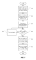
- FIG. 7 depicts a flowchart that illustrates a method for optimizing and enhancing delivery of application virtualization layers to client computing devices in accordance with one or more example embodiments.
- aspects described herein are directed towards systems, methods, and techniques for delivering application virtualization layers to one or more client computing devices.
- aspects described herein may be used to automatically analyze application virtualization layers to determine conflicts between the application virtualization layers and generate an actionable conflict resolution report comprising the results of the conflict analysis.
- Other aspects described herein may be used to resolve the conflicts indicated in the actionable conflict resolution report.
- Other aspects described herein may be used to prioritize and order the application virtualization layers based on the actionable conflict resolution report.
- Yet other aspects described herein may be used to merge the prioritized and ordered application virtualization layers and deliver the application virtualization layers to one or more client computing devices.
- FIGS. 1-6 Before discussing these concepts in greater detail, several examples of computing architecture and systems that may be used in implementing and/or otherwise providing various aspects of the disclosure will first be discussed with respect to FIGS. 1-6 .
- FIG. 1 illustrates one example of a system architecture and data processing device that may be used to implement one or more illustrative aspects described herein in a standalone and/or networked environment.
- Various network nodes 103 , 105 , 107 , and 109 may be interconnected via a wide area network (WAN) 101 , such as the Internet.
- WAN wide area network
- Other networks may also or alternatively be used, including private intranets, corporate networks, local area networks (LAN), metropolitan area networks (MAN), wireless networks, personal networks (PAN), and the like.
- Network 101 is for illustration purposes and may be replaced with fewer or additional computer networks.
- a local area network may have one or more of any known LAN topology and may use one or more of a variety of different protocols, such as Ethernet.
- Devices 103 , 105 , 107 , 109 and other devices may be connected to one or more of the networks via twisted pair wires, coaxial cable, fiber optics, radio waves or other communication media.
- network refers not only to systems in which remote storage devices are coupled together via one or more communication paths, but also to stand-alone devices that may be coupled, from time to time, to such systems that have storage capability. Consequently, the term “network” includes not only a “physical network” but also a “content network,” which is comprised of the data—attributable to a single entity—which resides across all physical networks.
- the components may include data server 103 , web server 105 , and client computers 107 , 109 .
- Data server 103 provides overall access, control and administration of databases and control software for performing one or more illustrative aspects describe herein.
- Data server 103 may be connected to web server 105 through which users interact with and obtain data as requested.
- data server 103 may act as a web server itself and be directly connected to the Internet.
- Data server 103 may be connected to web server 105 through the network 101 (e.g., the Internet), via direct or indirect connection, or via some other network.
- Users may interact with the data server 103 using remote computers 107 , 109 , e.g., using a web browser to connect to the data server 103 via one or more externally exposed web sites hosted by web server 105 .
- Client computers 107 , 109 may be used in concert with data server 103 to access data stored therein, or may be used for other purposes.
- a user may access web server 105 using an Internet browser, as is known in the art, or by executing a software application that communicates with web server 105 and/or data server 103 over a computer network (such as the Internet).
- FIG. 1 illustrates just one example of a network architecture that may be used, and those of skill in the art will appreciate that the specific network architecture and data processing devices used may vary, and are secondary to the functionality that they provide, as further described herein. For example, services provided by web server 105 and data server 103 may be combined on a single server.
- Each component 103 , 105 , 107 , 109 may be any type of known computer, server, or data processing device.
- Data server 103 e.g., may include a processor 111 controlling overall operation of the data server 103 .
- Data server 103 may further include random access memory (RAM) 113 , read only memory (ROM) 115 , network interface 117 , input/output interfaces 119 (e.g., keyboard, mouse, display, printer, etc.), and memory 121 .
- Input/output (I/O) 119 may include a variety of interface units and drives for reading, writing, displaying, and/or printing data or files.
- Memory 121 may further store operating system software 123 for controlling overall operation of the data processing device 103 , control logic 125 for instructing data server 103 to perform aspects described herein, and other application software 127 providing secondary, support, and/or other functionality which may or might not be used in conjunction with aspects described herein.
- the control logic may also be referred to herein as the data server software 125 .
- Functionality of the data server software may refer to operations or decisions made automatically based on rules coded into the control logic, made manually by a user providing input into the system, and/or a combination of automatic processing based on user input (e.g., queries, data updates, etc.).
- Memory 121 may also store data used in performance of one or more aspects described herein, including a first database 129 and a second database 131 .
- the first database may include the second database (e.g., as a separate table, report, etc.). That is, the information can be stored in a single database, or separated into different logical, virtual, or physical databases, depending on system design.
- Devices 105 , 107 , 109 may have similar or different architecture as described with respect to device 103 .
- data processing device 103 may be spread across multiple data processing devices, for example, to distribute processing load across multiple computers, to segregate transactions based on geographic location, user access level, quality of service (QoS), etc.
- QoS quality of service
- One or more aspects may be embodied in computer-usable or readable data and/or computer-executable instructions, such as in one or more program modules, executed by one or more computers or other devices as described herein.
- program modules include routines, programs, objects, components, data structures, etc. that perform particular tasks or implement particular abstract data types when executed by a processor in a computer or other device.
- the modules may be written in a source code programming language that is subsequently compiled for execution, or may be written in a scripting language such as (but not limited to) HyperText Markup Language (HTML) or Extensible Markup Language (XML).
- HTML HyperText Markup Language
- XML Extensible Markup Language
- the computer executable instructions may be stored on a computer readable medium such as a nonvolatile storage device.
- Any suitable computer readable storage media may be utilized, including hard disks, CD-ROMs, optical storage devices, magnetic storage devices, and/or any combination thereof.
- various transmission (non-storage) media representing data or events as described herein may be transferred between a source and a destination in the form of electromagnetic waves traveling through signal-conducting media such as metal wires, optical fibers, and/or wireless transmission media (e.g., air and/or space).
- signal-conducting media such as metal wires, optical fibers, and/or wireless transmission media (e.g., air and/or space).
- signal-conducting media such as metal wires, optical fibers, and/or wireless transmission media (e.g., air and/or space).
- Various aspects described herein may be embodied as a method, a data processing system, or a computer program product. Therefore, various functionalities may be embodied in whole or in part in software, firmware and/or hardware or hardware equivalents such as integrated circuits, field programmable gate arrays (F
- FIG. 2 depicts an example system architecture including a generic computing device 201 in an illustrative computing environment 200 that may be used according to one or more illustrative aspects described herein.
- Generic computing device 201 may be used as a server 206 a in a single-server or multi-server desktop virtualization system (e.g., a remote access or cloud system) configured to provide virtual machines for client access devices.
- the generic computing device 201 may have a processor 203 for controlling overall operation of the server and its associated components, including RAM 205 , ROM 207 , I/O module 209 , and memory 215 .
- I/O module 209 may include a mouse, keypad, touch screen, scanner, optical reader, and/or stylus (or other input device(s)) through which a user of generic computing device 201 may provide input, and may also include one or more of a speaker for providing audio output and a video display device for providing textual, audiovisual, and/or graphical output.
- Software may be stored within memory 215 and/or other storage to provide instructions to processor 203 for configuring generic computing device 201 into a special purpose computing device in order to perform various functions as described herein.
- memory 215 may store software used by the computing device 201 , such as an operating system 217 , application programs 219 , and an associated database 221 .
- Computing device 201 may operate in a networked environment supporting connections to one or more remote computers, such as terminals 240 (also referred to as client devices).
- the terminals 240 may be personal computers, mobile devices, laptop computers, tablets, or servers that include many or all of the elements described above with respect to the generic computing device 103 or 201 .
- the network connections depicted in FIG. 2 include a local area network (LAN) 225 and a wide area network (WAN) 229 , but may also include other networks.
- LAN local area network
- WAN wide area network
- computing device 201 may be connected to the LAN 225 through a network interface or adapter 223 .
- computing device 201 When used in a WAN networking environment, computing device 201 may include a modem 227 or other wide area network interface for establishing communications over the WAN 229 , such as computer network 230 (e.g., the Internet). It will be appreciated that the network connections shown are illustrative and other means of establishing a communications link between the computers may be used.
- Computing device 201 and/or terminals 240 may also be mobile terminals (e.g., mobile phones, smartphones, personal digital assistants (PDAs), notebooks, etc.) including various other components, such as a battery, speaker, and antennas (not shown).
- PDAs personal digital assistants
- aspects described herein may also be operational with numerous other specially adapted or special purpose computing system environments or configurations.
- Examples of other computing systems, environments, and/or configurations that may be suitable for use with aspects described herein include, but are not limited to, personal computers, server computers, hand-held or laptop devices, multiprocessor systems, microprocessor-based systems, set top boxes, programmable consumer electronics, network personal computers (PCs), minicomputers, mainframe computers, distributed computing environments that include any of the above systems or devices, and the like.
- one or more client devices 240 may be in communication with one or more servers 206 a - 206 n (generally referred to herein as “server(s) 206 ”).
- the computing environment 200 may include a network appliance installed between the server(s) 206 and client machine(s) 240 .
- the network appliance may manage client/server connections, and in some cases can load balance client connections amongst a plurality of backend servers 206 .
- the client machine(s) 240 may in some embodiments be referred to as a single client machine 240 or a single group of client machines 240
- server(s) 206 may be referred to as a single server 206 or a single group of servers 206 .
- a single client machine 240 communicates with more than one server 206
- a single server 206 communicates with more than one client machine 240
- a single client machine 240 communicates with a single server 206 .
- a client machine 240 can, in some embodiments, be referenced by any one of the following non-exhaustive terms: client machine(s); client(s); client computer(s); client device(s); client computing device(s); local machine; remote machine; client node(s); endpoint(s); or endpoint node(s).
- the server 206 in some embodiments, may be referenced by any one of the following non-exhaustive terms: server(s), local machine; remote machine; server farm(s), or host computing device(s).
- the client machine 240 may be a virtual machine.
- the virtual machine may be any virtual machine, while in some embodiments the virtual machine may be any virtual machine managed by a Type 1 or Type 2 hypervisor, for example, a hypervisor developed by Citrix Systems, IBM, VMware, or any other hypervisor.
- the virtual machine may be managed by a hypervisor, while in aspects the virtual machine may be managed by a hypervisor executing on a server 206 or a hypervisor executing on a client 240 .
- Some embodiments include a client device 240 that displays application output generated by an application remotely executing on a server 206 or other remotely located machine.
- the client device 240 may execute a virtual machine receiver program or application to display the output in an application window, a browser, or other output window.
- the application is a desktop, while in other examples the application is an application that generates or presents a desktop.
- a desktop may include a graphical shell providing a user interface for an instance of an operating system in which local and/or remote applications can be integrated.
- Applications as used herein, are programs that execute after an instance of an operating system (and, optionally, also the desktop) has been loaded.
- the server 206 uses a remote presentation protocol or other program to send data to a thin-client or remote-display application executing on the client to present display output generated by an application executing on the server 206 .
- the thin-client or remote-display protocol can be any one of the following non-exhaustive list of protocols: the Independent Computing Architecture (ICA) protocol developed by Citrix Systems, Inc. of Ft. Lauderdale, Fla.; or the Remote Desktop Protocol (RDP) manufactured by the Microsoft Corporation of Redmond, Wash.
- ICA Independent Computing Architecture
- RDP Remote Desktop Protocol
- a remote computing environment may include more than one server 206 a - 206 n such that the servers 206 a - 206 n are logically grouped together into a server farm 206 , for example, in a cloud computing environment.
- the server farm 206 may include servers 206 that are geographically dispersed while and logically grouped together, or servers 206 that are located proximate to each other while logically grouped together.
- Geographically dispersed servers 206 a - 206 n within a server farm 206 can, in some embodiments, communicate using a WAN (wide), MAN (metropolitan), or LAN (local), where different geographic regions can be characterized as: different continents; different regions of a continent; different countries; different states; different cities; different campuses; different rooms; or any combination of the preceding geographical locations.
- the server farm 206 may be administered as a single entity, while in other embodiments the server farm 206 can include multiple server farms.
- a server farm may include servers 206 that execute a substantially similar type of operating system platform (e.g., WINDOWS, UNIX, LINUX, iOS, ANDROID, SYMBIAN, etc.)
- server farm 206 may include a first group of one or more servers that execute a first type of operating system platform, and a second group of one or more servers that execute a second type of operating system platform.
- Server 206 may be configured as any type of server, as needed, e.g., a file server, an application server, a web server, a proxy server, an appliance, a network appliance, a gateway, an application gateway, a gateway server, a virtualization server, a deployment server, a Secure Sockets Layer (SSL) VPN server, a firewall, a web server, an application server or as a master application server, a server executing an active directory, or a server executing an application acceleration program that provides firewall functionality, application functionality, or load balancing functionality.
- SSL Secure Sockets Layer
- Other server types may also be used.
- Some embodiments include a first server 206 a that receives requests from a client machine 240 , forwards the request to a second server 206 b , and responds to the request generated by the client machine 240 with a response from the second server 206 b .
- First server 206 a may acquire an enumeration of applications available to the client machine 240 and well as address information associated with an application server 206 hosting an application identified within the enumeration of applications.
- First server 206 a can then present a response to the client's request using a web interface, and communicate directly with the client 240 to provide the client 240 with access to an identified application.
- One or more clients 240 and/or one or more servers 206 may transmit data over network 230 , e.g., network 101 .
- FIG. 3 shows a high-level architecture of an illustrative desktop virtualization system.
- the desktop virtualization system may be single-server or multi-server system, or cloud system, including at least one virtualization server 301 configured to provide virtual desktops and/or virtual applications to one or more client access devices 240 .
- a desktop refers to a graphical environment or space in which one or more applications may be hosted and/or executed.
- a desktop may include a graphical shell providing a user interface for an instance of an operating system in which local and/or remote applications can be integrated.
- Applications may include programs that execute after an instance of an operating system (and, optionally, also the desktop) has been loaded.
- Each instance of the operating system may be physical (e.g., one operating system per device) or virtual (e.g., many instances of an OS running on a single device).
- Each application may be executed on a local device, or executed on a remotely located device (e.g., remoted).
- a computer device 301 may be configured as a virtualization server in a virtualization environment, for example, a single-server, multi-server, or cloud computing environment.
- Virtualization server 301 illustrated in FIG. 3 can be deployed as and/or implemented by one or more embodiments of the server 206 illustrated in FIG. 2 or by other known computing devices.
- Included in virtualization server 301 is a hardware layer that can include one or more physical disks 304 , one or more physical devices 306 , one or more physical processors 308 and one or more physical memories 316 .
- firmware 312 can be stored within a memory element in the physical memory 316 and can be executed by one or more of the physical processors 308 .
- Virtualization server 301 may further include an operating system 314 that may be stored in a memory element in the physical memory 316 and executed by one or more of the physical processors 308 . Still further, a hypervisor 302 may be stored in a memory element in the physical memory 316 and can be executed by one or more of the physical processors 308 .
- Executing on one or more of the physical processors 308 may be one or more virtual machines 332 A-C (generally 332 ). Each virtual machine 332 may have a virtual disk 326 A-C and a virtual processor 328 A-C.
- a first virtual machine 332 A may execute, using a virtual processor 328 A, a control program 320 that includes a tools stack 324 .
- Control program 320 may be referred to as a control virtual machine, Dom 0 Domain 0 or other virtual machine used for system administration and/or control.
- one or more virtual machines 332 B-C can execute, using a virtual processor 328 B-C, a guest operating system 330 A-B.
- Virtualization server 301 may include a hardware layer 310 with one or more pieces of hardware that communicate with the virtualization server 301 .
- the hardware layer 310 can include one or more physical disks 304 , one or more physical devices 306 , one or more physical processors 308 , and one or more memory 216 .
- Physical components 304 , 306 , 308 , and 316 may include, for example, any of the components described above.
- Physical devices 306 may include, for example, a network interface card, a video card, a keyboard, a mouse, an input device, a monitor, a display device, speakers, an optical drive, a storage device, a universal serial bus connection, a printer, a scanner, a network element (e.g., router, firewall, network address translator, load balancer, virtual private network (VPN) gateway, Dynamic Host Configuration Protocol (DHCP) router, etc.), or any device connected to or communicating with virtualization server 301 .
- Physical memory 316 in the hardware layer 310 may include any type of memory. Physical memory 316 may store data, and in some embodiments may store one or more programs, or set of executable instructions.
- FIG. 3 illustrates an embodiment where firmware 312 is stored within the physical memory 316 of virtualization server 301 . Programs or executable instructions stored in the physical memory 316 can be executed by the one or more processors 308 of virtualization server 301 .
- Virtualization server 301 may also include a hypervisor 302 .
- hypervisor 302 may be a program executed by processors 308 on virtualization server 301 to create and manage any number of virtual machines 332 .
- Hypervisor 302 may be referred to as a virtual machine monitor, or platform virtualization software.
- hypervisor 302 can be any combination of executable instructions and hardware that monitors virtual machines executing on a computing machine.
- Hypervisor 302 may be Type 2 hypervisor, where the hypervisor that executes within an operating system 314 executing on the virtualization server 301 . Virtual machines then execute at a level above the hypervisor.
- the Type 2 hypervisor executes within the context of a user's operating system such that the Type 2 hypervisor interacts with the user's operating system.
- one or more virtualization servers 301 in a virtualization environment may instead include a Type 1 hypervisor (not shown).
- a Type 1 hypervisor may execute on the virtualization server 301 by directly accessing the hardware and resources within the hardware layer 310 . That is, while a Type 2 hypervisor 302 accesses system resources through a host operating system 314 , as shown, a Type 1 hypervisor may directly access all system resources without the host operating system 314 .
- a Type 1 hypervisor may execute directly on one or more physical processors 308 of virtualization server 301 , and may include program data stored in the physical memory 316 .
- Hypervisor 302 can provide virtual resources to operating systems 330 or control programs 320 executing on virtual machines 332 in any manner that simulates the operating systems 330 or control programs 320 having direct access to system resources.
- System resources can include, but are not limited to, physical devices 306 , physical disks 304 , physical processors 308 , physical memory 316 and any other component included in virtualization server 301 hardware layer 310 .
- Hypervisor 302 may be used to emulate virtual hardware, partition physical hardware, virtualize physical hardware, and/or execute virtual machines that provide access to computing environments. In still other embodiments, hypervisor 302 controls processor scheduling and memory partitioning for a virtual machine 332 executing on virtualization server 301 .
- Hypervisor 302 may include those manufactured by VMWare, Inc., of Palo Alto, Calif.; the XENPROJECT hypervisor, an open source product whose development is overseen by the open source XenProject.org community; HyperV, VirtualServer or virtual PC hypervisors provided by Microsoft, or others.
- virtualization server 301 executes a hypervisor 302 that creates a virtual machine platform on which guest operating systems may execute.
- the virtualization server 301 may be referred to as a host server.
- An example of such a virtualization server is the XENSERVER provided by Citrix Systems, Inc., of Fort Lauderdale, Fla.
- Hypervisor 302 may create one or more virtual machines 332 B-C (generally 332 ) in which guest operating systems 330 execute.
- hypervisor 302 may load a virtual machine image to create a virtual machine 332 .
- the hypervisor 302 may executes a guest operating system 330 within virtual machine 332 .
- virtual machine 332 may execute guest operating system 330 .
- hypervisor 302 may control the execution of at least one virtual machine 332 .
- hypervisor 302 may presents at least one virtual machine 332 with an abstraction of at least one hardware resource provided by the virtualization server 301 (e.g., any hardware resource available within the hardware layer 310 ).
- hypervisor 302 may control the manner in which virtual machines 332 access physical processors 308 available in virtualization server 301 . Controlling access to physical processors 308 may include determining whether a virtual machine 332 should have access to a processor 308 , and how physical processor capabilities are presented to the virtual machine 332 .
- virtualization server 301 may host or execute one or more virtual machines 332 .
- a virtual machine 332 is a set of executable instructions that, when executed by a processor 308 , imitate the operation of a physical computer such that the virtual machine 332 can execute programs and processes much like a physical computing device. While FIG. 3 illustrates an embodiment where a virtualization server 301 hosts three virtual machines 332 , in other embodiments virtualization server 301 can host any number of virtual machines 332 .
- Hypervisor 302 in some embodiments, provides each virtual machine 332 with a unique virtual view of the physical hardware, memory, processor and other system resources available to that virtual machine 332 .
- the unique virtual view can be based on one or more of virtual machine permissions, application of a policy engine to one or more virtual machine identifiers, a user accessing a virtual machine, the applications executing on a virtual machine, networks accessed by a virtual machine, or any other desired criteria.
- hypervisor 302 may create one or more unsecure virtual machines 332 and one or more secure virtual machines 332 . Unsecure virtual machines 332 may be prevented from accessing resources, hardware, memory locations, and programs that secure virtual machines 332 may be permitted to access.
- hypervisor 302 may provide each virtual machine 332 with a substantially similar virtual view of the physical hardware, memory, processor and other system resources available to the virtual machines 332 .
- Each virtual machine 332 may include a virtual disk 326 A-C (generally 326 ) and a virtual processor 328 A-C (generally 328 .)
- the virtual disk 326 in some embodiments, is a virtualized view of one or more physical disks 304 of the virtualization server 301 , or a portion of one or more physical disks 304 of the virtualization server 301 .
- the virtualized view of the physical disks 304 can be generated, provided and managed by the hypervisor 302 .
- hypervisor 302 provides each virtual machine 332 with a unique view of the physical disks 304 .
- the particular virtual disk 326 included in each virtual machine 332 can be unique when compared with the other virtual disks 326 .
- a virtual processor 328 can be a virtualized view of one or more physical processors 308 of the virtualization server 301 .
- the virtualized view of the physical processors 308 can be generated, provided and managed by hypervisor 302 .
- virtual processor 328 has substantially all of the same characteristics of at least one physical processor 308 .
- virtual processor 308 provides a modified view of physical processors 308 such that at least some of the characteristics of the virtual processor 328 are different than the characteristics of the corresponding physical processor 308 .
- FIG. 4 illustrates an example of a cloud computing environment (or cloud system) 400 .
- client computers 411 - 414 may communicate with a cloud management server 410 to access the computing resources (e.g., host servers 403 , storage resources 404 , and network resources 405 ) of the cloud system.
- computing resources e.g., host servers 403 , storage resources 404 , and network resources 405 .
- Management server 410 may be implemented on one or more physical servers.
- the management server 410 may run, for example, CLOUDSTACK by Citrix Systems, Inc. of Ft. Lauderdale, Fla., or OPENSTACK, among others.
- Management server 410 may manage various computing resources, including cloud hardware and software resources, for example, host computers 403 , data storage devices 404 , and networking devices 405 .
- the cloud hardware and software resources may include private and/or public components.
- a cloud may be configured as a private cloud to be used by one or more particular customers or client computers 411 - 414 and/or over a private network.
- public clouds or hybrid public-private clouds may be used by other customers over an open or hybrid networks.
- Management server 410 may be configured to provide user interfaces through which cloud operators and cloud customers may interact with the cloud system.
- the management server 410 may provide a set of application programming interfaces (APIs) and/or one or more cloud operator console applications (e.g., web-based on standalone applications) with user interfaces to allow cloud operators to manage the cloud resources, configure the virtualization layer, manage customer accounts, and perform other cloud administration tasks.
- the management server 410 also may include a set of APIs and/or one or more customer console applications with user interfaces configured to receive cloud computing requests from end users via client computers 411 - 414 , for example, requests to create, modify, or destroy virtual machines within the cloud.
- Client computers 411 - 414 may connect to management server 410 via the Internet or other communication network, and may request access to one or more of the computing resources managed by management server 410 .
- the management server 410 may include a resource manager configured to select and provision physical resources in the hardware layer of the cloud system based on the client requests.
- the management server 410 and additional components of the cloud system may be configured to provision, create, and manage virtual machines and their operating environments (e.g., hypervisors, storage resources, services offered by the network elements, etc.) for customers at client computers 411 - 414 , over a network (e.g., the Internet), providing customers with computational resources, data storage services, networking capabilities, and computer platform and application support.
- Cloud systems also may be configured to provide various specific services, including security systems, development environments, user interfaces, and the like.
- Certain clients 411 - 414 may be related, for example, different client computers creating virtual machines on behalf of the same end user, or different users affiliated with the same company or organization. In other examples, certain clients 411 - 414 may be unrelated, such as users affiliated with different companies or organizations. For unrelated clients, information on the virtual machines or storage of any one user may be hidden from other users.
- zones 401 - 402 may refer to a collocated set of physical computing resources. Zones may be geographically separated from other zones in the overall cloud of computing resources. For example, zone 401 may be a first cloud datacenter located in California, and zone 402 may be a second cloud datacenter located in Florida. Management sever 410 may be located at one of the availability zones, or at a separate location. Each zone may include an internal network that interfaces with devices that are outside of the zone, such as the management server 410 , through a gateway. End users of the cloud (e.g., clients 411 - 414 ) might or might not be aware of the distinctions between zones.
- an end user may request the creation of a virtual machine having a specified amount of memory, processing power, and network capabilities.
- the management server 410 may respond to the user's request and may allocate the resources to create the virtual machine without the user knowing whether the virtual machine was created using resources from zone 401 or zone 402 .
- the cloud system may allow end users to request that virtual machines (or other cloud resources) are allocated in a specific zone or on specific resources 403 - 405 within a zone.
- each zone 401 - 402 may include an arrangement of various physical hardware components (or computing resources) 403 - 405 , for example, physical hosting resources (or processing resources), physical network resources, physical storage resources, switches, and additional hardware resources that may be used to provide cloud computing services to customers.
- the physical hosting resources in a cloud zone 401 - 402 may include one or more computer servers 403 , such as the virtualization servers 301 described above, which may be configured to create and host virtual machine instances.
- the physical network resources in a cloud zone 401 or 402 may include one or more network elements 405 (e.g., network service providers) comprising hardware and/or software configured to provide a network service to cloud customers, such as firewalls, network address translators, load balancers, virtual private network (VPN) gateways, Dynamic Host Configuration Protocol (DHCP) routers, and the like.
- the storage resources in the cloud zone 401 - 402 may include storage disks (e.g., solid state drives (SSDs), magnetic hard disks, etc.) and other storage devices.
- the example cloud computing environment shown in FIG. 4 also may include a virtualization layer (e.g., as shown in FIGS. 1-3 ) with additional hardware and/or software resources configured to create and manage virtual machines and provide other services to customers using the physical resources in the cloud.
- the virtualization layer may include hypervisors, as described above in FIG. 3 , along with other components to provide network virtualizations, storage virtualizations, etc.
- the virtualization layer may be as a separate layer from the physical resource layer, or may share some or all of the same hardware and/or software resources with the physical resource layer.
- the virtualization layer may include a hypervisor installed in each of the virtualization servers 403 with the physical computing resources.
- WINDOWS AZURE Microsoft Corporation of Redmond Wash.
- AMAZON EC2 Amazon.com Inc. of Seattle, Wash.
- IBM BLUE CLOUD IBM BLUE CLOUD
- aspects of the disclosure generally relate to optimizations and enhancements to the delivery of application virtualization layers to client computing devices.
- various examples illustrating how application virtualization layers may be analyzed, prioritized, merged, and delivered in accordance with one or more embodiments will be discussed.
- FIG. 5 depicts an illustrative system architecture which may be used for delivering application virtualization layers to one or more client computing devices in accordance with one or more example embodiments.
- the application virtualization layer optimization service 520 may obtain and process application virtualization layers 510 and deliver the processed application virtualization layers to one or more client computing devices 540 over network 530 .
- the architecture of the system depicted in FIG. 5 is similar in many respects to the architecture of computing environments described above with reference to FIGS. 1, 2, and 4 and may include additional features not mentioned above. Some of the components of the computing environments described above with reference to FIGS. 1, 2, and 4 have been omitted for the sake of simplicity.
- the application virtualization layers 510 may contain the information necessary to deliver one or more applications to client computing devices 540 and for the client computing devices 540 to execute the one or more applications contained in the application virtualization layers 510 .
- the application virtualization layers 510 may include files, system registry entries, and data related to one or more applications to be delivered and executed by the client computing devices 540 .
- the data related to the one or more applications may include Windows Management Instrumentation (WMI) data entries, Component Object Model (COM+) registration information, Security Account Manager (SAM) database entries, and the like.
- WMI Windows Management Instrumentation
- COM+ Component Object Model
- SAM Security Account Manager
- the one or more applications comprised within the application virtualization layers 510 may appear to be natively installed on the client computing devices 540 once the client computing devices 540 have executed the contents of the application virtualization layers 510 . That is, from the point of view of the application and of the client computing device, there may be no difference between an application being installed natively on the client computing device and being deployed via an application virtualization layer.
- the application virtualization layers 510 may be created such that they are independent from a base operating system.
- the application virtualization layers 510 may be capable of deploying to a variety of operating system types and versions.
- an application virtualization layer 510 may be deployed to a client computing device 540 running one type of operating system (e.g., WINDOWS 7, manufactured by Microsoft Corporation of Redmond, Wash.) and the same application virtualization layer 510 may also be deployed to another client computing device 540 running another type of operating system (e.g., WINDOWS 8, manufactured by Microsoft Corporation of Redmond, Wash.)
- the application virtualization layers 510 may be deployed on client computing devices 540 with a pre-installed operating system.
- an application virtualization layer may comprise an operating system for the client computing devices 540 .
- the client computing device 540 may execute the operating system comprised by an application virtualization layer 510 .
- Computing environment 500 may include one or more computing devices.
- computing environment 500 may include an application virtualization layer optimization service 520 .
- the application virtualization layer optimization service 520 may comprise a single-server, a multi-server system, or a cloud-based system, including at least one virtualization server, as described above with reference to FIG. 4 .
- the application virtualization layer optimization service 520 may be configured to perform one or more of the various functions described herein.
- Computing environment 500 also may include one or more client computing devices 540 .
- Client computing devices 540 may be any type of computing device capable of receiving and processing input via one or more user interfaces, providing output via one or more user interfaces and communicating input, output, and/or other information to and/or from one or more other computing devices.
- client computing devices 540 may be a server computer, a desktop computer, laptop computer, tablet computer, smart phone, or the like.
- client computing devices 540 may be one of the computing devices described above in reference to FIGS. 1, 2, and 4 (e.g., devices 103 , 105 , 107 , 109 , 240 , and 411 - 414 .)
- client computing devices 540 may be special-purpose computing devices configured to perform specific functions.
- client computing devices 540 may store, execute, and/or otherwise include various software applications for receiving, storing, and executing application virtualization layers delivered by the application virtualization layer optimization service 520 over network 530 .
- Computing environment 500 also may include one or more networks, which may interconnect the application virtualization layer optimization service 520 and the client computing devices 540 .
- computing environment 500 may include network 530 , which may include one or more private networks (which may, e.g., be operated by and/or associated with an organization that operates application virtualization layer optimization service 520 and which may include one or more local area networks, wide area networks, virtual private networks, etc.) and/or one or more public networks (e.g., the Internet).
- private networks which may, e.g., be operated by and/or associated with an organization that operates application virtualization layer optimization service 520 and which may include one or more local area networks, wide area networks, virtual private networks, etc.
- public networks e.g., the Internet
- the application virtualization layer optimization service 520 may include a layer analysis service 522 , a layer conflict resolution module 524 , a layer prioritization module 526 , and a layer merging module 528 .
- Each of the modules comprised in the application virtualization layer optimization service 520 may be implemented using hardware, software, or a combination of hardware and software.
- the layer analysis service 522 may be configured to generate an actionable conflict resolution report based on an analysis of the application virtualization layers 510 obtained by the application virtualization layer optimization service 520 .
- the layer analysis service 522 is described in further detail below in reference to FIG. 6 .
- the layer conflict resolution module 524 may be configured to resolve the conflicts indicated on the actionable conflict resolution report generated by the layer analysis service 522 .
- the layer conflict resolution module 524 may iterate through all the actionable conflicts comprised in the actionable conflict resolution report and determine a resolution to the conflict in a manner that maximizes compatibility of the application virtualization layers.
- the actionable conflict resolution report may indicate that two application virtualization layers comprise different versions of the same file and the files are located in the same location in the file system.
- the layer conflict resolution module 524 may determine that application virtualization layer compatibility is maximized by assigning a higher priority to the file with the higher version.
- the actionable conflict resolution report may indicate that two application virtualization layers comprise different versions of a Component Object Model (COM+) application programming interface (API).
- the layer conflict resolution module 524 may determine that application virtualization layer compatibility is maximized by assigning a higher priority to the interface with the higher priority.
- an application virtualization layer may contain a 64-bit version of an application. In such a scenario, the layer conflict resolution module 524 may prevent the application virtualization layer from being delivered to client computing devices 540 which are not capable of executing 64-bit applications.
- the layer prioritization module 526 may be configured to arrange the application virtualization layers 510 in a priority or precedence order based on the priority information comprised in the actionable conflict resolution report and based on the priority determinations made by the layer conflict resolution module 524 .
- the application virtualization layers 510 that have been assigned a higher priority may take precedence over the application virtualization layers 510 that have been assigned a lower priority.
- the layer prioritization module 526 may generate an application virtualization layer priority report that may be used by other computing devices, e.g. the client computing devices 540 , to determine the priority or precedence order for deploying the application virtualization layers 510 .
- the layer merging module 528 may be configured to merge the ordered application virtualization layers 510 into a single application virtualization layer.
- the merged single application virtualization layer may deliver all the applications comprised within each of the application virtualization layers 510 . Accordingly, only a single application virtualization layer may be delivered and executed by the client computing devices 540 .
- the application virtualization layer optimization service 520 may deliver the ordered application virtualization layers 510 to the client computing devices 540 and the client computing devices 540 may merge the application virtualization layers 510 locally. Merging the ordered application virtualization layers 510 may create a single application virtualization layer which may be solely attached or streamed to the client computing devices 540 .
- the ordered application virtualization layers 510 may be merged with an application virtualization layer comprising an operating system, and the resulting merged layer may replace the operating system image on the client computing devices 540 .
- the layer merging module 528 may be configured to not include an isolation layer between the merged application virtualization layers 510 . That is, the one or more applications in the resulting merged application virtualization layer may not be isolated from the other applications in the merged application virtualization layer.
- Merging the ordered application virtualization layers 510 may improve performance of the client computing device 540 as most of the processing to merge the ordered application virtualization layers 510 is performed once per delivery rather than on every boot sequence of the client computing device 540 . Additionally, merging multiple application virtualization layers into a single layer may permit delivery of an amount of application virtualization layers that may otherwise exceed the maximum supported capacity of the target client computing device for virtual disks. Another advantage of merging the application virtualization layers 510 may be a reduced Input/Output Operations per Second (IOPS) footprint on the client computing device 540 . Thus the merged application virtualization layer may provide improved run-time performance when compared to delivering the application virtualization layers 510 separately.
- IOPS Input/Output Operations per Second
- the application virtualization layer optimization service 520 may be configured to deliver the merged application virtualization layers 510 to the compatible client computing devices 540 .
- the application virtualization layer optimization service 520 may determine which of the client computing devices 540 are compatible with the merged application virtualization layers 510 , based on the actionable conflict resolution report. Based on the determination of which client computing devices 540 are compatible, the application virtualization layer optimization service 520 may deliver the merged application virtualization layers 510 only to those client computing devices 540 which are compatible with the merged application virtualization layers 510 .
- the application virtualization layer optimization service 520 may deliver the ordered application virtualization layers 510 which are compatible with the client computing devices 540 and the client computing devices 540 may merge the ordered and compatible application virtualization layers 510 locally.
- the application virtualization layers 510 may be delivered to the client computing devices 540 at various stages: prior to startup, during the startup sequence, during user login, and post user login.
- the application virtualization layer optimization service 520 may deliver the ordered and merged application virtualization layers 510 to a storage device which the client computing devices 540 may access during their startup sequence.
- the application virtualization layer optimization service 520 may deliver a single merged application virtualization layer 510 which comprises the operating system and all the applications designated for the client computing devices 540 .
- the client computing devices 540 may attach or mount the single merged application virtualization layer 510 and use the layer as their boot-up operating system image or replace the operating system image in the hypervisor if or when the client computing device 540 is a virtual machine.
- the application virtualization layer optimization service 520 may support applications that require early boot drivers installed on the target environment in order to provide their functionality.
- the application virtualization layer optimization service 520 may also deliver the application virtualization layers 510 on demand during the startup sequence of the client computing devices 540 .
- the client computing devices 540 may attach or mount the delivered application virtualization layers 510 .
- the application virtualization layers 510 may be streamed to the client computing devices 540 as a one or more virtual disks using provisioning technologies like Citrix Provisioning Services (PVS) and Machine Creation Services (MCS), both manufactured by Citrix Systems, Inc. of Ft. Lauderdale, Fla., and App-V manufactured by Microsoft Corporation of Redmond, Wash.
- provisioning technologies like Citrix Provisioning Services (PVS) and Machine Creation Services (MCS), both manufactured by Citrix Systems, Inc. of Ft. Lauderdale, Fla., and App-V manufactured by Microsoft Corporation of Redmond, Wash.
- the application virtualization layer optimization service 520 may deliver the application virtualization layers 510 to the client computing devices 540 in response to a user login on a particular client computing device 540 .
- the application virtualization layer optimization service 520 may be further configured to determine which application virtualization layers 510 to deliver based on the identity of the user login into the particular client computing device 540 .
- the application virtualization layer optimization service 520 may update one or more applications comprised in one or more of the application virtualization layers 510 . For example, a new version of an application may have become available which may require that one of the application virtualization layers 510 be updated to include the new version of the application.
- the layer analysis service 522 may re-analyze the updated application virtualization layers 510 with the remaining application virtualization layers 510 and generate an updated actionable conflict resolution report. Subsequently, as described in greater detail above, the application virtualization layer optimization service 520 may resolve the conflicts indicated in the updated actionable conflict resolution report, as well as, order and merge the application virtualization layers 510 based on the updated actionable conflict resolution report.
- the application virtualization layer optimization service 520 may be configured to deliver the updated application virtualization layers 510 to the client computing devices 540 as described above.
- the application virtualization layer optimization service 520 may obtain one or more application virtualization layers 510 each comprising one of a variety of types and versions of operating systems, as well as, one or more application virtualization layers 510 each comprising a single application. In these other embodiments, the application virtualization layer optimization service 520 may automatically determine which application virtualization layers 510 to merge and deliver to the client computing devices 540 based on the capabilities of the targeted client computing devices 540 and the users login into these client computing devices 540 .
- application virtualization layer optimization service 520 may deliver a different mix of operating system and applications to a client computing device 540 based on the type of device (e.g., desktop, laptop, smartphone) and on the user login into the device (e.g. users from engineering department may receive one set of applications, while users from accounting department may receive a different set of applications.)
- the type of device e.g., desktop, laptop, smartphone
- the user login into the device e.g. users from engineering department may receive one set of applications, while users from accounting department may receive a different set of applications.
- the application virtualization layer optimization service 520 may automatically analyze and resolve conflicts, prioritize, and merge application virtualization layers 510 to be delivered to client computing devices 540 .
- the application virtualization layer optimization service 520 may determine which application virtualization layers 510 to deliver to the client computing devices 540 based on the capabilities of the client computing devices and the role of the users login into the particular client computing devices 540 .
- the application virtualization layers may be updated as needed and automatically analyzed, prioritized, merged, and delivered with the remaining application virtualization layers.
- FIG. 5 illustrates just one example of a system architecture that may be used, and those of skill in the art will appreciate that the specific system architecture and computing devices used may vary, and are secondary to the functionality that they provide, as further described herein.
- the services provided by the application virtualization layer optimization service 520 may be executed on a single computing device or on multiple computing devices at one site or distributed across multiple sites and interconnected by a communication network.
- FIG. 6 illustrates an exemplary layer analysis service 522 suitable for use as part of the application virtualization layer optimization service 520 described above in reference to FIG. 5 .
- the layer analysis service 522 may analyze the application virtualization layers 510 and provide the results of said analysis to the layer conflict resolution module 524 , the layer prioritization module 526 , and the layer merging module 528 .
- the layer analysis service 522 may comprise a layer characterization module 610 , a layer characteristics comparator 620 , a layer analysis engine 630 , and a conflict resolution report generator 640 .
- the layer characterization module 610 may determine or extract one or more operational characteristics for each application virtualization layer 510 .
- the application virtualization layer operational characteristics may include at least one or more of the following: boot-time dependencies, run-time dependencies, login-time dependencies, operating system dependencies, computer architecture dependencies, framework dependencies, shared library dependencies, dynamically-linked library dependencies, application programming interface dependencies, and services dependencies. Additionally, the layer characterization module 610 may be further configured to determine the operational characteristics for each application included in each application virtualization layer 510 .
- an external computing device may determine the operational characteristics of the application virtualization layers 510 , and of the applications within the application virtualization layers 510 , and may provide the information to the layer analysis service 522 .
- the layer characteristics comparator 620 may perform comparisons of the operational characteristics for each application virtualization layer 510 with the operational characteristics of every other application virtualization layer 510 . Additionally, the layer characteristics comparator 620 may be further configured to compare the operational characteristics for each application included in each application virtualization layer 510 with the operational characteristics of every other application included in the particular application virtualization layer 510 .
- the layer analysis engine 630 may be configured to execute one or more algorithms on the collected operational characteristics to determine compatibility conflicts between the application virtualization layers 510 .
- the layer analysis engine 630 may prescribe remediations for the compatibility conflicts between the application virtualization layers 510 .
- the layer analysis engine 630 may perform basic compatibility checks. For example, the layer analysis engine 630 may check the application virtualization layers 510 for dependencies on obsolete components not supported on any modern operating systems (e.g., Graphical Identification and Authentication, GINA.)
- the layer analysis engine 630 may also perform operating system dependency checks. For example, the layer analysis engine 630 may analyze the application virtualization layers 510 to determine whether they require a 32-bit or a 64-bit operating system.
- the layer analysis engine 630 may also check for dependencies on obsolete technologies (e.g. NetDDE on Windows Server 2012 ), for dependencies on side-by-side libraries (e.g., .NET framework), and for missing dependencies. Additionally, the layer analysis engine 630 may perform compatibility checks with operating system components included in the application virtualization layers 510 . For example, the layer analysis engine 630 may check for dependencies on specific versions of Windows runtime libraries. Other possible sources of conflicts may include, but are not limited to, file system, system registry database, Windows Management Instrumentation (WMI) database, Component Object Model (COM+) registration database, Security Account Manager (SAM) database, system catalog database, and dynamically-linked library version conflicts.
- WMI Windows Management Instrumentation
- COM+ Component Object Model
- SAM Security Account Manager
- the layer analysis algorithms are not limited to the examples described herein.
- the layer analysis engine may be configured to accept new algorithms which may be added to improve the quality of the analysis.
- the layer analysis engine 630 may further determine a priority or precedence order for the application virtualization layers 510 based on the comparison data from the layer characteristics comparator 620 and the compatibility conflicts. The layer analysis engine 630 may predict a prioritization of application virtualization layers 510 with respect to other application virtualization layers 510 in order to maximize application compatibility. Additionally, by analyzing the operational characteristics of the application virtualization layers 510 , the layer analysis engine 630 may determine incompatible application virtualization layers 510 . By further examining and analyzing the operational characteristics of the application virtualization layers 510 , the layer analysis engine 630 may also determine candidate target computing devices which are compatible with the application virtualization layers 510 .
- the layer analysis engine 630 may determine whether an application virtualization layer created for a Microsoft Windows 7 operating system may also be compatible with a client computing device using a Microsoft Windows 8 operating system. Furthermore, the layer analysis engine 630 may also determine deployment methods which are compatible with the application virtualization layers 510 . For example, the layer analysis engine 630 may determine whether an application virtualization layer 510 may be delivered to a client computing device 540 in response to a user login or whether the application virtualization layer 510 requires to be delivered during the startup sequence of the client computing device 540 .
- the conflict resolution report generator 640 may be configured to generate an actionable conflict resolution report which comprises the determined compatibility conflicts and their corresponding prescribed remediations. That is, the actionable conflict resolution report may contain actionable rules to resolve the detected compatibility conflicts between the application virtualization layers 510 in order to prevent destabilizing the client computing devices 540 or causing the delivered applications to malfunction.
- the actionable conflict resolution report may also comprise determinations of a priority or precedence order for the application virtualization layers 510 , determinations of candidate target computing devices compatible with the application virtualization layers 510 , and determinations of compatible deployment methods, as determined by the layer analysis engine 630 .
- the conflict resolution report generator 640 may be configured to provide the actionable conflict resolution report to the layer conflict resolution module 524 , the layer prioritization module 526 , and the layer merging module 528 , for further processing. In some embodiments, the conflict resolution report generator 640 may be further configured to provide the actionable conflict resolution report to other computing devices or systems (e.g., client computing devices 540 ) in order to support run-time merging of the delivered application virtualization layers 510 . In yet other embodiments, the conflict resolution report generator 640 may provide the actionable conflict resolution report to an end user to assist the end user in manually merging application virtualization layers.
- FIG. 6 illustrates just one example of a system architecture that may be used, and those of skill in the art will appreciate that the specific system architecture and computing devices used may vary, and are secondary to the functionality that they provide, as further described herein.
- the services provided by the layer analysis service 522 may be executed on a single computing device or on multiple computing devices at one site or distributed across multiple sites and interconnected by a communication network.
- the layer analysis service 522 may include one or more computing devices executing application management software, or other software that performs application compatibility and testing functions.
- An example of such software that may be used is APPDNA, which is commercially available from Citrix Systems, Inc., of Fort Lauderdale, Fla.
- FIG. 7 depicts a flowchart that illustrates a method for optimizing and enhancing delivery of application virtualization layers to client computing devices in accordance with one or more example embodiments.
- the algorithm shown in FIG. 7 and other similar examples described herein may be performed in a computing environment such as the systems illustrated in FIGS. 5 and 6 , as well as other systems having different architectures (e.g., all or part of FIGS. 1-4 ).
- the method illustrated in FIG. 7 and/or one or more steps thereof may be embodied in a computer-readable medium, such as a non-transitory computer readable memory.
- the application virtualization layer optimization service 520 may identify one or more application virtualization layers 510 to be delivered to one or more client computing devices.
- Each application virtualization layer 510 represents a package of one or more applications.
- the application virtualization layers 510 may include files, system registry entries, and data related to one or more applications to be delivered and executed by the client computing devices 540 .
- the layer analysis service 522 may analyze the application virtualization layers 510 for conflicts between the application virtualization layers 510 .
- the layer analysis service may compare one or more operational characteristics of the application virtualization layers 510 to determine compatibility conflicts, prescribe resolutions for said compatibility conflicts, determine a priority or precedence order, and determine candidate target computing devices and deployment methods compatible with the application virtualization layers 510 .
- the application virtualization layer operational characteristics may include at least one or more of the following: boot-time dependencies, run-time dependencies, login-time dependencies, operating system dependencies, computer architecture dependencies, framework dependencies, shared library dependencies, dynamically-linked library dependencies, application programming interface dependencies, and services dependencies.
- the layer analysis service 522 may generate an actionable conflict resolution report comprising the results of the analysis performed in step 720 . That is, the actionable conflict resolution report may include the compatibility conflicts and their corresponding prescribed remediations determined in step 720 , as well as, determinations of a priority or precedence order for the application virtualization layers 510 , determinations of candidate target computing devices compatible with the application virtualization layers 510 , and determinations of compatible deployment methods, as determined by the layer analysis engine 630 .
- the application virtualization layer optimization service 520 may determine whether any of the conflicts indicated on the actionable conflict resolution report remain unresolved. Based on the determination, the application virtualization layer optimization service 520 may proceed to step 750 to resolve the actionable conflict indicated on the actionable conflict resolution report. The application virtualization layer optimization service 520 may continue to repeat steps 740 and 750 until all conflicts indicated on the actionable conflict resolution report are resolved. In step 760 , application virtualization layer optimization service 520 may order the application virtualization layers 510 in a priority or precedence order based on the priority information comprised in the actionable conflict resolution report and based on the priority determinations made by the layer conflict resolution module 524 . In step 770 , the application virtualization layer optimization service 520 may deliver the application virtualization layers 510 to the one or more client computing devices 540 .
Landscapes
- Engineering & Computer Science (AREA)
- Software Systems (AREA)
- Theoretical Computer Science (AREA)
- Physics & Mathematics (AREA)
- General Engineering & Computer Science (AREA)
- General Physics & Mathematics (AREA)
- Information Transfer Between Computers (AREA)
- User Interface Of Digital Computer (AREA)
Abstract
Description
Claims (20)
Priority Applications (1)
| Application Number | Priority Date | Filing Date | Title |
|---|---|---|---|
| US15/637,089 US9959136B2 (en) | 2015-05-11 | 2017-06-29 | Optimizations and enhancements of application virtualization layers |
Applications Claiming Priority (3)
| Application Number | Priority Date | Filing Date | Title |
|---|---|---|---|
| US201562159394P | 2015-05-11 | 2015-05-11 | |
| US14/963,837 US9753759B2 (en) | 2015-12-09 | 2015-12-09 | Optimizations and enhancements of application virtualization layers |
| US15/637,089 US9959136B2 (en) | 2015-05-11 | 2017-06-29 | Optimizations and enhancements of application virtualization layers |
Related Parent Applications (1)
| Application Number | Title | Priority Date | Filing Date |
|---|---|---|---|
| US14/963,837 Continuation US9753759B2 (en) | 2015-05-11 | 2015-12-09 | Optimizations and enhancements of application virtualization layers |
Publications (2)
| Publication Number | Publication Date |
|---|---|
| US20170300351A1 US20170300351A1 (en) | 2017-10-19 |
| US9959136B2 true US9959136B2 (en) | 2018-05-01 |
Family
ID=59020541
Family Applications (2)
| Application Number | Title | Priority Date | Filing Date |
|---|---|---|---|
| US14/963,837 Active 2035-12-23 US9753759B2 (en) | 2015-05-11 | 2015-12-09 | Optimizations and enhancements of application virtualization layers |
| US15/637,089 Active US9959136B2 (en) | 2015-05-11 | 2017-06-29 | Optimizations and enhancements of application virtualization layers |
Family Applications Before (1)
| Application Number | Title | Priority Date | Filing Date |
|---|---|---|---|
| US14/963,837 Active 2035-12-23 US9753759B2 (en) | 2015-05-11 | 2015-12-09 | Optimizations and enhancements of application virtualization layers |
Country Status (1)
| Country | Link |
|---|---|
| US (2) | US9753759B2 (en) |
Cited By (1)
| Publication number | Priority date | Publication date | Assignee | Title |
|---|---|---|---|---|
| US9974430B2 (en) | 2008-02-12 | 2018-05-22 | Innurvation, Inc. | Ingestible endoscopic optical scanning device |
Families Citing this family (5)
| Publication number | Priority date | Publication date | Assignee | Title |
|---|---|---|---|---|
| US10691547B1 (en) * | 2016-03-21 | 2020-06-23 | EMC IP Holding Company LLC | Backup and recovery for end-user computing in virtual desktop environments |
| US11126455B2 (en) * | 2019-09-27 | 2021-09-21 | Citrix Systems, Inc. | System and methods for provisioning different versions of a virtual application |
| US11182134B2 (en) * | 2020-02-24 | 2021-11-23 | Hewlett Packard Enterprise Development Lp | Self-adjustable end-to-end stack programming |
| CN112333003B (en) * | 2020-10-13 | 2022-11-08 | 北京京东尚科信息技术有限公司 | Method and device for acquiring proprietary cloud container cluster gene information |
| US12468551B2 (en) * | 2021-06-24 | 2025-11-11 | International Business Machines Corporation | Multi-source device policy management |
Citations (2)
| Publication number | Priority date | Publication date | Assignee | Title |
|---|---|---|---|---|
| US20050050155A1 (en) * | 2003-08-28 | 2005-03-03 | International Business Machines Corporation | System and method for providing shared web modules |
| US7076764B2 (en) * | 2002-09-05 | 2006-07-11 | Bea Systems, Inc. | System and method for software module architecture language and compliance checking |
-
2015
- 2015-12-09 US US14/963,837 patent/US9753759B2/en active Active
-
2017
- 2017-06-29 US US15/637,089 patent/US9959136B2/en active Active
Patent Citations (2)
| Publication number | Priority date | Publication date | Assignee | Title |
|---|---|---|---|---|
| US7076764B2 (en) * | 2002-09-05 | 2006-07-11 | Bea Systems, Inc. | System and method for software module architecture language and compliance checking |
| US20050050155A1 (en) * | 2003-08-28 | 2005-03-03 | International Business Machines Corporation | System and method for providing shared web modules |
Non-Patent Citations (2)
| Title |
|---|
| Apr. 5, 2017-U.S. Notice of Allowance-U.S. Appl. No. 14/963,837. |
| Apr. 5, 2017—U.S. Notice of Allowance—U.S. Appl. No. 14/963,837. |
Cited By (1)
| Publication number | Priority date | Publication date | Assignee | Title |
|---|---|---|---|---|
| US9974430B2 (en) | 2008-02-12 | 2018-05-22 | Innurvation, Inc. | Ingestible endoscopic optical scanning device |
Also Published As
| Publication number | Publication date |
|---|---|
| US20170300351A1 (en) | 2017-10-19 |
| US20170168861A1 (en) | 2017-06-15 |
| US9753759B2 (en) | 2017-09-05 |
Similar Documents
| Publication | Publication Date | Title |
|---|---|---|
| US12219022B2 (en) | Browser server session transfer | |
| US11252228B2 (en) | Multi-tenant multi-session catalogs with machine-level isolation | |
| US11108845B2 (en) | Rendering a web application in a cloud service | |
| AU2019326538B2 (en) | Service pool architecture for multitenant services to support canary release | |
| US10050934B2 (en) | Redirector for secure web browsing | |
| EP2992422B1 (en) | Undifferentiated service domains | |
| US9910765B2 (en) | Providing testing environments for software applications using virtualization and a native hardware layer | |
| US9959136B2 (en) | Optimizations and enhancements of application virtualization layers | |
| CN105074665B (en) | Migration tools for desktop virtualization | |
| US10545625B2 (en) | Redirection of web content | |
| US11997170B2 (en) | Automated migration of monolithic applications to container platforms | |
| US11385973B1 (en) | High-availability for power-managed virtual desktop access | |
| US20230275954A1 (en) | Remote browser session presentation with local browser tabs | |
| US11366832B2 (en) | Cloud services management | |
| US11226850B2 (en) | Scenario based multiple applications on-screen | |
| US10984015B2 (en) | Multi-select dropdown state replication | |
| US10382293B2 (en) | Scoped view of cloud control plane for development of new services |
Legal Events
| Date | Code | Title | Description |
|---|---|---|---|
| STCF | Information on status: patent grant |
Free format text: PATENTED CASE |
|
| MAFP | Maintenance fee payment |
Free format text: PAYMENT OF MAINTENANCE FEE, 4TH YEAR, LARGE ENTITY (ORIGINAL EVENT CODE: M1551); ENTITY STATUS OF PATENT OWNER: LARGE ENTITY Year of fee payment: 4 |
|
| AS | Assignment |
Owner name: WILMINGTON TRUST, NATIONAL ASSOCIATION, DELAWARE Free format text: SECURITY INTEREST;ASSIGNOR:CITRIX SYSTEMS, INC.;REEL/FRAME:062079/0001 Effective date: 20220930 |
|
| AS | Assignment |
Owner name: GOLDMAN SACHS BANK USA, AS COLLATERAL AGENT, NEW YORK Free format text: SECOND LIEN PATENT SECURITY AGREEMENT;ASSIGNORS:TIBCO SOFTWARE INC.;CITRIX SYSTEMS, INC.;REEL/FRAME:062113/0001 Effective date: 20220930 Owner name: WILMINGTON TRUST, NATIONAL ASSOCIATION, AS NOTES COLLATERAL AGENT, DELAWARE Free format text: PATENT SECURITY AGREEMENT;ASSIGNORS:TIBCO SOFTWARE INC.;CITRIX SYSTEMS, INC.;REEL/FRAME:062113/0470 Effective date: 20220930 Owner name: BANK OF AMERICA, N.A., AS COLLATERAL AGENT, NORTH CAROLINA Free format text: PATENT SECURITY AGREEMENT;ASSIGNORS:TIBCO SOFTWARE INC.;CITRIX SYSTEMS, INC.;REEL/FRAME:062112/0262 Effective date: 20220930 |
|
| AS | Assignment |
Owner name: CLOUD SOFTWARE GROUP, INC. (F/K/A TIBCO SOFTWARE INC.), FLORIDA Free format text: RELEASE AND REASSIGNMENT OF SECURITY INTEREST IN PATENT (REEL/FRAME 062113/0001);ASSIGNOR:GOLDMAN SACHS BANK USA, AS COLLATERAL AGENT;REEL/FRAME:063339/0525 Effective date: 20230410 Owner name: CITRIX SYSTEMS, INC., FLORIDA Free format text: RELEASE AND REASSIGNMENT OF SECURITY INTEREST IN PATENT (REEL/FRAME 062113/0001);ASSIGNOR:GOLDMAN SACHS BANK USA, AS COLLATERAL AGENT;REEL/FRAME:063339/0525 Effective date: 20230410 Owner name: WILMINGTON TRUST, NATIONAL ASSOCIATION, AS NOTES COLLATERAL AGENT, DELAWARE Free format text: PATENT SECURITY AGREEMENT;ASSIGNORS:CLOUD SOFTWARE GROUP, INC. (F/K/A TIBCO SOFTWARE INC.);CITRIX SYSTEMS, INC.;REEL/FRAME:063340/0164 Effective date: 20230410 |
|
| AS | Assignment |
Owner name: WILMINGTON TRUST, NATIONAL ASSOCIATION, AS NOTES COLLATERAL AGENT, DELAWARE Free format text: SECURITY INTEREST;ASSIGNORS:CLOUD SOFTWARE GROUP, INC. (F/K/A TIBCO SOFTWARE INC.);CITRIX SYSTEMS, INC.;REEL/FRAME:067662/0568 Effective date: 20240522 |
|
| AS | Assignment |
Owner name: WILMINGTON TRUST, NATIONAL ASSOCIATION, AS NOTES COLLATERAL AGENT, DELAWARE Free format text: PATENT SECURITY AGREEMENT;ASSIGNORS:CLOUD SOFTWARE GROUP, INC.;CITRIX SYSTEMS, INC.;REEL/FRAME:072488/0172 Effective date: 20250814 |
|
| MAFP | Maintenance fee payment |
Free format text: PAYMENT OF MAINTENANCE FEE, 8TH YEAR, LARGE ENTITY (ORIGINAL EVENT CODE: M1552); ENTITY STATUS OF PATENT OWNER: LARGE ENTITY Year of fee payment: 8 |