US9950341B2 - Systems and methods for fabricating spiral coils with atomized bioactive coatings - Google Patents
Systems and methods for fabricating spiral coils with atomized bioactive coatings Download PDFInfo
- Publication number
- US9950341B2 US9950341B2 US14/567,152 US201414567152A US9950341B2 US 9950341 B2 US9950341 B2 US 9950341B2 US 201414567152 A US201414567152 A US 201414567152A US 9950341 B2 US9950341 B2 US 9950341B2
- Authority
- US
- United States
- Prior art keywords
- coating
- coil
- spiral coil
- polymer
- recited
- Prior art date
- Legal status (The legal status is an assumption and is not a legal conclusion. Google has not performed a legal analysis and makes no representation as to the accuracy of the status listed.)
- Active, expires
Links
- 238000000576 coating method Methods 0.000 title claims abstract description 161
- 238000000034 method Methods 0.000 title claims abstract description 106
- 230000000975 bioactive effect Effects 0.000 title description 12
- 239000011248 coating agent Substances 0.000 claims abstract description 153
- 229920000642 polymer Polymers 0.000 claims abstract description 122
- 230000029663 wound healing Effects 0.000 claims abstract description 9
- 239000010410 layer Substances 0.000 claims description 87
- 239000002904 solvent Substances 0.000 claims description 43
- 238000000151 deposition Methods 0.000 claims description 39
- 230000008021 deposition Effects 0.000 claims description 34
- 239000000314 lubricant Substances 0.000 claims description 20
- 239000012867 bioactive agent Substances 0.000 claims description 19
- 230000000284 resting effect Effects 0.000 claims description 10
- 238000000935 solvent evaporation Methods 0.000 claims description 9
- 238000004132 cross linking Methods 0.000 claims description 5
- 238000010438 heat treatment Methods 0.000 claims description 4
- 230000001678 irradiating effect Effects 0.000 claims description 4
- 239000013047 polymeric layer Substances 0.000 claims description 4
- 206010002329 Aneurysm Diseases 0.000 abstract description 13
- 201000008450 Intracranial aneurysm Diseases 0.000 abstract description 10
- 239000003795 chemical substances by application Substances 0.000 abstract description 5
- 238000005137 deposition process Methods 0.000 abstract description 2
- 239000000243 solution Substances 0.000 description 47
- 239000000463 material Substances 0.000 description 36
- 238000005516 engineering process Methods 0.000 description 31
- 229920001606 poly(lactic acid-co-glycolic acid) Polymers 0.000 description 20
- -1 e.g. Polymers 0.000 description 19
- BASFCYQUMIYNBI-UHFFFAOYSA-N platinum Chemical compound [Pt] BASFCYQUMIYNBI-UHFFFAOYSA-N 0.000 description 19
- 238000000889 atomisation Methods 0.000 description 17
- 229920000728 polyester Polymers 0.000 description 17
- 239000002245 particle Substances 0.000 description 15
- 229920000747 poly(lactic acid) Polymers 0.000 description 14
- CSCPPACGZOOCGX-UHFFFAOYSA-N Acetone Chemical compound CC(C)=O CSCPPACGZOOCGX-UHFFFAOYSA-N 0.000 description 12
- AEMRFAOFKBGASW-UHFFFAOYSA-N Glycolic acid Chemical compound OCC(O)=O AEMRFAOFKBGASW-UHFFFAOYSA-N 0.000 description 11
- 229940079593 drug Drugs 0.000 description 11
- 239000003814 drug Substances 0.000 description 11
- 229910052751 metal Inorganic materials 0.000 description 11
- 239000002184 metal Substances 0.000 description 11
- 206010061218 Inflammation Diseases 0.000 description 10
- 230000004054 inflammatory process Effects 0.000 description 10
- 239000011159 matrix material Substances 0.000 description 10
- 230000000770 proinflammatory effect Effects 0.000 description 10
- 239000002253 acid Substances 0.000 description 9
- 229910052697 platinum Inorganic materials 0.000 description 9
- 230000001052 transient effect Effects 0.000 description 9
- HEDRZPFGACZZDS-UHFFFAOYSA-N Chloroform Chemical compound ClC(Cl)Cl HEDRZPFGACZZDS-UHFFFAOYSA-N 0.000 description 8
- 230000006870 function Effects 0.000 description 8
- JVTAAEKCZFNVCJ-UHFFFAOYSA-N lactic acid Chemical class CC(O)C(O)=O JVTAAEKCZFNVCJ-UHFFFAOYSA-N 0.000 description 8
- 229920001577 copolymer Polymers 0.000 description 7
- 239000007788 liquid Substances 0.000 description 7
- XEKOWRVHYACXOJ-UHFFFAOYSA-N Ethyl acetate Chemical compound CCOC(C)=O XEKOWRVHYACXOJ-UHFFFAOYSA-N 0.000 description 6
- 229960000633 dextran sulfate Drugs 0.000 description 6
- 239000000203 mixture Substances 0.000 description 6
- 239000000178 monomer Substances 0.000 description 6
- 208000024891 symptom Diseases 0.000 description 6
- 239000004721 Polyphenylene oxide Substances 0.000 description 5
- 230000002378 acidificating effect Effects 0.000 description 5
- 229910045601 alloy Inorganic materials 0.000 description 5
- 239000000956 alloy Substances 0.000 description 5
- 230000007423 decrease Effects 0.000 description 5
- 238000001035 drying Methods 0.000 description 5
- 229920002313 fluoropolymer Polymers 0.000 description 5
- 229960004275 glycolic acid Drugs 0.000 description 5
- 235000014655 lactic acid Nutrition 0.000 description 5
- 229920000058 polyacrylate Polymers 0.000 description 5
- 229920000570 polyether Polymers 0.000 description 5
- 229920000193 polymethacrylate Polymers 0.000 description 5
- 230000008569 process Effects 0.000 description 5
- 238000011282 treatment Methods 0.000 description 5
- 241000124008 Mammalia Species 0.000 description 4
- 229940061720 alpha hydroxy acid Drugs 0.000 description 4
- 150000001280 alpha hydroxy acids Chemical class 0.000 description 4
- 235000010957 calcium stearoyl-2-lactylate Nutrition 0.000 description 4
- OEUVSBXAMBLPES-UHFFFAOYSA-L calcium stearoyl-2-lactylate Chemical compound [Ca+2].CCCCCCCCCCCCCCCCCC(=O)OC(C)C(=O)OC(C)C([O-])=O.CCCCCCCCCCCCCCCCCC(=O)OC(C)C(=O)OC(C)C([O-])=O OEUVSBXAMBLPES-UHFFFAOYSA-L 0.000 description 4
- 239000003102 growth factor Substances 0.000 description 4
- 230000001965 increasing effect Effects 0.000 description 4
- 229920001432 poly(L-lactide) Polymers 0.000 description 4
- 229920000151 polyglycol Polymers 0.000 description 4
- 239000010695 polyglycol Substances 0.000 description 4
- CXMXRPHRNRROMY-UHFFFAOYSA-N sebacic acid Chemical compound OC(=O)CCCCCCCCC(O)=O CXMXRPHRNRROMY-UHFFFAOYSA-N 0.000 description 4
- 239000007787 solid Substances 0.000 description 4
- WFKWXMTUELFFGS-UHFFFAOYSA-N tungsten Chemical compound [W] WFKWXMTUELFFGS-UHFFFAOYSA-N 0.000 description 4
- 229910052721 tungsten Inorganic materials 0.000 description 4
- 239000010937 tungsten Substances 0.000 description 4
- XLYOFNOQVPJJNP-UHFFFAOYSA-N water Substances O XLYOFNOQVPJJNP-UHFFFAOYSA-N 0.000 description 4
- 238000009736 wetting Methods 0.000 description 4
- WEVYAHXRMPXWCK-UHFFFAOYSA-N Acetonitrile Chemical compound CC#N WEVYAHXRMPXWCK-UHFFFAOYSA-N 0.000 description 3
- YMWUJEATGCHHMB-UHFFFAOYSA-N Dichloromethane Chemical compound ClCCl YMWUJEATGCHHMB-UHFFFAOYSA-N 0.000 description 3
- 108050007372 Fibroblast Growth Factor Proteins 0.000 description 3
- 102000018233 Fibroblast Growth Factor Human genes 0.000 description 3
- 108010010803 Gelatin Proteins 0.000 description 3
- 241001465754 Metazoa Species 0.000 description 3
- ZMXDDKWLCZADIW-UHFFFAOYSA-N N,N-Dimethylformamide Chemical compound CN(C)C=O ZMXDDKWLCZADIW-UHFFFAOYSA-N 0.000 description 3
- 229920000954 Polyglycolide Polymers 0.000 description 3
- 229920001710 Polyorthoester Polymers 0.000 description 3
- BQCADISMDOOEFD-UHFFFAOYSA-N Silver Chemical compound [Ag] BQCADISMDOOEFD-UHFFFAOYSA-N 0.000 description 3
- 229920002472 Starch Polymers 0.000 description 3
- RTAQQCXQSZGOHL-UHFFFAOYSA-N Titanium Chemical compound [Ti] RTAQQCXQSZGOHL-UHFFFAOYSA-N 0.000 description 3
- QCWXUUIWCKQGHC-UHFFFAOYSA-N Zirconium Chemical compound [Zr] QCWXUUIWCKQGHC-UHFFFAOYSA-N 0.000 description 3
- 230000008901 benefit Effects 0.000 description 3
- JFDZBHWFFUWGJE-UHFFFAOYSA-N benzonitrile Chemical compound N#CC1=CC=CC=C1 JFDZBHWFFUWGJE-UHFFFAOYSA-N 0.000 description 3
- 239000001913 cellulose Substances 0.000 description 3
- 229920002678 cellulose Polymers 0.000 description 3
- 235000010980 cellulose Nutrition 0.000 description 3
- 229960001231 choline Drugs 0.000 description 3
- OEYIOHPDSNJKLS-UHFFFAOYSA-N choline Chemical compound C[N+](C)(C)CCO OEYIOHPDSNJKLS-UHFFFAOYSA-N 0.000 description 3
- 238000013270 controlled release Methods 0.000 description 3
- 238000010586 diagram Methods 0.000 description 3
- 201000010099 disease Diseases 0.000 description 3
- 208000037265 diseases, disorders, signs and symptoms Diseases 0.000 description 3
- 150000002148 esters Chemical group 0.000 description 3
- 239000000945 filler Substances 0.000 description 3
- 229920000159 gelatin Polymers 0.000 description 3
- 235000019322 gelatine Nutrition 0.000 description 3
- 235000011852 gelatine desserts Nutrition 0.000 description 3
- 125000002887 hydroxy group Chemical group [H]O* 0.000 description 3
- 239000004310 lactic acid Substances 0.000 description 3
- 230000004048 modification Effects 0.000 description 3
- 238000012986 modification Methods 0.000 description 3
- 239000004633 polyglycolic acid Substances 0.000 description 3
- 238000012805 post-processing Methods 0.000 description 3
- 238000002360 preparation method Methods 0.000 description 3
- 102000004169 proteins and genes Human genes 0.000 description 3
- 108090000623 proteins and genes Proteins 0.000 description 3
- 229910052709 silver Inorganic materials 0.000 description 3
- 239000004332 silver Substances 0.000 description 3
- 241000894007 species Species 0.000 description 3
- 239000010935 stainless steel Substances 0.000 description 3
- 229910001220 stainless steel Inorganic materials 0.000 description 3
- 235000019698 starch Nutrition 0.000 description 3
- 239000008107 starch Substances 0.000 description 3
- 239000010936 titanium Substances 0.000 description 3
- 229910052719 titanium Inorganic materials 0.000 description 3
- 229910052726 zirconium Inorganic materials 0.000 description 3
- 229920002134 Carboxymethyl cellulose Polymers 0.000 description 2
- 229920002307 Dextran Polymers 0.000 description 2
- IAZDPXIOMUYVGZ-UHFFFAOYSA-N Dimethylsulphoxide Chemical compound CS(C)=O IAZDPXIOMUYVGZ-UHFFFAOYSA-N 0.000 description 2
- 108010066486 EGF Family of Proteins Proteins 0.000 description 2
- 102000018386 EGF Family of Proteins Human genes 0.000 description 2
- 108090000723 Insulin-Like Growth Factor I Proteins 0.000 description 2
- 102000013275 Somatomedins Human genes 0.000 description 2
- 235000021355 Stearic acid Nutrition 0.000 description 2
- 108010009583 Transforming Growth Factors Proteins 0.000 description 2
- 102000009618 Transforming Growth Factors Human genes 0.000 description 2
- 102000005789 Vascular Endothelial Growth Factors Human genes 0.000 description 2
- 108010019530 Vascular Endothelial Growth Factors Proteins 0.000 description 2
- 150000007513 acids Chemical class 0.000 description 2
- 239000000853 adhesive Substances 0.000 description 2
- 230000001070 adhesive effect Effects 0.000 description 2
- 150000008064 anhydrides Chemical class 0.000 description 2
- HUMNYLRZRPPJDN-UHFFFAOYSA-N benzaldehyde Chemical compound O=CC1=CC=CC=C1 HUMNYLRZRPPJDN-UHFFFAOYSA-N 0.000 description 2
- 150000004649 carbonic acid derivatives Chemical class 0.000 description 2
- 239000001768 carboxy methyl cellulose Substances 0.000 description 2
- 235000010948 carboxy methyl cellulose Nutrition 0.000 description 2
- 239000008112 carboxymethyl-cellulose Substances 0.000 description 2
- 230000015556 catabolic process Effects 0.000 description 2
- 239000011247 coating layer Substances 0.000 description 2
- 239000007857 degradation product Substances 0.000 description 2
- 238000011161 development Methods 0.000 description 2
- 229960002086 dextran Drugs 0.000 description 2
- 230000002708 enhancing effect Effects 0.000 description 2
- 230000035876 healing Effects 0.000 description 2
- 229920001519 homopolymer Polymers 0.000 description 2
- 239000001866 hydroxypropyl methyl cellulose Substances 0.000 description 2
- 229920003088 hydroxypropyl methyl cellulose Polymers 0.000 description 2
- 235000010979 hydroxypropyl methyl cellulose Nutrition 0.000 description 2
- 229960003943 hypromellose Drugs 0.000 description 2
- 239000003999 initiator Substances 0.000 description 2
- 230000007774 longterm Effects 0.000 description 2
- 108010033949 polytyrosine Proteins 0.000 description 2
- 229920002451 polyvinyl alcohol Polymers 0.000 description 2
- 238000007639 printing Methods 0.000 description 2
- 230000001681 protective effect Effects 0.000 description 2
- 230000005855 radiation Effects 0.000 description 2
- 230000009467 reduction Effects 0.000 description 2
- 238000011160 research Methods 0.000 description 2
- 238000001878 scanning electron micrograph Methods 0.000 description 2
- 239000007921 spray Substances 0.000 description 2
- 238000005507 spraying Methods 0.000 description 2
- 239000000758 substrate Substances 0.000 description 2
- 210000001519 tissue Anatomy 0.000 description 2
- 230000007704 transition Effects 0.000 description 2
- 230000008728 vascular permeability Effects 0.000 description 2
- 229920002554 vinyl polymer Polymers 0.000 description 2
- PAPBSGBWRJIAAV-UHFFFAOYSA-N ε-Caprolactone Chemical group O=C1CCCCCO1 PAPBSGBWRJIAAV-UHFFFAOYSA-N 0.000 description 2
- BYEAHWXPCBROCE-UHFFFAOYSA-N 1,1,1,3,3,3-hexafluoropropan-2-ol Chemical compound FC(F)(F)C(O)C(F)(F)F BYEAHWXPCBROCE-UHFFFAOYSA-N 0.000 description 1
- WSLDOOZREJYCGB-UHFFFAOYSA-N 1,2-Dichloroethane Chemical compound ClCCCl WSLDOOZREJYCGB-UHFFFAOYSA-N 0.000 description 1
- RYHBNJHYFVUHQT-UHFFFAOYSA-N 1,4-Dioxane Chemical compound C1COCCO1 RYHBNJHYFVUHQT-UHFFFAOYSA-N 0.000 description 1
- RKDVKSZUMVYZHH-UHFFFAOYSA-N 1,4-dioxane-2,5-dione Chemical compound O=C1COC(=O)CO1 RKDVKSZUMVYZHH-UHFFFAOYSA-N 0.000 description 1
- QCDWFXQBSFUVSP-UHFFFAOYSA-N 2-phenoxyethanol Chemical compound OCCOC1=CC=CC=C1 QCDWFXQBSFUVSP-UHFFFAOYSA-N 0.000 description 1
- 241000251468 Actinopterygii Species 0.000 description 1
- 229920000856 Amylose Polymers 0.000 description 1
- 241000283690 Bos taurus Species 0.000 description 1
- 241000282472 Canis lupus familiaris Species 0.000 description 1
- 241000283707 Capra Species 0.000 description 1
- 241000700198 Cavia Species 0.000 description 1
- 241000282693 Cercopithecidae Species 0.000 description 1
- 229920001661 Chitosan Polymers 0.000 description 1
- UDSFAEKRVUSQDD-UHFFFAOYSA-N Dimethyl adipate Chemical compound COC(=O)CCCCC(=O)OC UDSFAEKRVUSQDD-UHFFFAOYSA-N 0.000 description 1
- 238000012276 Endovascular treatment Methods 0.000 description 1
- 241000283086 Equidae Species 0.000 description 1
- 229920003141 Eudragit® S 100 Polymers 0.000 description 1
- 241000282326 Felis catus Species 0.000 description 1
- WQZGKKKJIJFFOK-GASJEMHNSA-N Glucose Natural products OC[C@H]1OC(O)[C@H](O)[C@@H](O)[C@@H]1O WQZGKKKJIJFFOK-GASJEMHNSA-N 0.000 description 1
- 229920002907 Guar gum Polymers 0.000 description 1
- 241001272567 Hominoidea Species 0.000 description 1
- 229920000663 Hydroxyethyl cellulose Polymers 0.000 description 1
- 239000004354 Hydroxyethyl cellulose Substances 0.000 description 1
- JVTAAEKCZFNVCJ-REOHCLBHSA-N L-lactic acid Chemical compound C[C@H](O)C(O)=O JVTAAEKCZFNVCJ-REOHCLBHSA-N 0.000 description 1
- FYYHWMGAXLPEAU-UHFFFAOYSA-N Magnesium Chemical compound [Mg] FYYHWMGAXLPEAU-UHFFFAOYSA-N 0.000 description 1
- 241000699670 Mus sp. Species 0.000 description 1
- 241000283973 Oryctolagus cuniculus Species 0.000 description 1
- 241000282579 Pan Species 0.000 description 1
- 241001494479 Pecora Species 0.000 description 1
- ABLZXFCXXLZCGV-UHFFFAOYSA-N Phosphorous acid Chemical compound OP(O)=O ABLZXFCXXLZCGV-UHFFFAOYSA-N 0.000 description 1
- 229920002732 Polyanhydride Polymers 0.000 description 1
- 239000002202 Polyethylene glycol Substances 0.000 description 1
- 229920000331 Polyhydroxybutyrate Polymers 0.000 description 1
- 239000004372 Polyvinyl alcohol Substances 0.000 description 1
- 241000700159 Rattus Species 0.000 description 1
- 241000283984 Rodentia Species 0.000 description 1
- 229920002125 Sokalan® Polymers 0.000 description 1
- 208000032851 Subarachnoid Hemorrhage Diseases 0.000 description 1
- QAOWNCQODCNURD-UHFFFAOYSA-L Sulfate Chemical compound [O-]S([O-])(=O)=O QAOWNCQODCNURD-UHFFFAOYSA-L 0.000 description 1
- 241000282898 Sus scrofa Species 0.000 description 1
- 239000004809 Teflon Substances 0.000 description 1
- 229920006362 Teflon® Polymers 0.000 description 1
- 206010052428 Wound Diseases 0.000 description 1
- 208000027418 Wounds and injury Diseases 0.000 description 1
- 238000005299 abrasion Methods 0.000 description 1
- 230000004075 alteration Effects 0.000 description 1
- 238000010171 animal model Methods 0.000 description 1
- 239000007864 aqueous solution Substances 0.000 description 1
- 230000004071 biological effect Effects 0.000 description 1
- 229940088623 biologically active substance Drugs 0.000 description 1
- 210000000988 bone and bone Anatomy 0.000 description 1
- 210000004556 brain Anatomy 0.000 description 1
- 125000003178 carboxy group Chemical group [H]OC(*)=O 0.000 description 1
- 229940105329 carboxymethylcellulose Drugs 0.000 description 1
- 238000004140 cleaning Methods 0.000 description 1
- 238000005056 compaction Methods 0.000 description 1
- 230000001010 compromised effect Effects 0.000 description 1
- 238000004590 computer program Methods 0.000 description 1
- 210000002808 connective tissue Anatomy 0.000 description 1
- 238000007796 conventional method Methods 0.000 description 1
- 238000007334 copolymerization reaction Methods 0.000 description 1
- 150000004985 diamines Chemical class 0.000 description 1
- 150000002009 diols Chemical class 0.000 description 1
- 238000003618 dip coating Methods 0.000 description 1
- 238000012377 drug delivery Methods 0.000 description 1
- 230000000694 effects Effects 0.000 description 1
- 238000010894 electron beam technology Methods 0.000 description 1
- 230000003073 embolic effect Effects 0.000 description 1
- 238000005530 etching Methods 0.000 description 1
- 238000011156 evaluation Methods 0.000 description 1
- 238000001704 evaporation Methods 0.000 description 1
- 230000008020 evaporation Effects 0.000 description 1
- 238000013467 fragmentation Methods 0.000 description 1
- 238000006062 fragmentation reaction Methods 0.000 description 1
- 239000008273 gelatin Substances 0.000 description 1
- 230000009477 glass transition Effects 0.000 description 1
- 239000008103 glucose Substances 0.000 description 1
- 229960001031 glucose Drugs 0.000 description 1
- 235000001727 glucose Nutrition 0.000 description 1
- 230000037313 granulation tissue formation Effects 0.000 description 1
- 239000000665 guar gum Substances 0.000 description 1
- 235000010417 guar gum Nutrition 0.000 description 1
- 229960002154 guar gum Drugs 0.000 description 1
- 238000009998 heat setting Methods 0.000 description 1
- 230000003118 histopathologic effect Effects 0.000 description 1
- 235000019447 hydroxyethyl cellulose Nutrition 0.000 description 1
- 229940071826 hydroxyethyl cellulose Drugs 0.000 description 1
- 230000004968 inflammatory condition Effects 0.000 description 1
- 230000002757 inflammatory effect Effects 0.000 description 1
- 210000004698 lymphocyte Anatomy 0.000 description 1
- 210000002540 macrophage Anatomy 0.000 description 1
- 229910052749 magnesium Inorganic materials 0.000 description 1
- 239000011777 magnesium Substances 0.000 description 1
- 238000004519 manufacturing process Methods 0.000 description 1
- 230000002503 metabolic effect Effects 0.000 description 1
- 230000000921 morphogenic effect Effects 0.000 description 1
- 210000003739 neck Anatomy 0.000 description 1
- 210000000440 neutrophil Anatomy 0.000 description 1
- HLXZNVUGXRDIFK-UHFFFAOYSA-N nickel titanium Chemical compound [Ti].[Ti].[Ti].[Ti].[Ti].[Ti].[Ti].[Ti].[Ti].[Ti].[Ti].[Ni].[Ni].[Ni].[Ni].[Ni].[Ni].[Ni].[Ni].[Ni].[Ni].[Ni].[Ni].[Ni].[Ni] HLXZNVUGXRDIFK-UHFFFAOYSA-N 0.000 description 1
- 229910001000 nickel titanium Inorganic materials 0.000 description 1
- 231100000252 nontoxic Toxicity 0.000 description 1
- 230000003000 nontoxic effect Effects 0.000 description 1
- QNGNSVIICDLXHT-UHFFFAOYSA-N para-ethylbenzaldehyde Natural products CCC1=CC=C(C=O)C=C1 QNGNSVIICDLXHT-UHFFFAOYSA-N 0.000 description 1
- 229920001277 pectin Polymers 0.000 description 1
- 239000001814 pectin Substances 0.000 description 1
- 235000010987 pectin Nutrition 0.000 description 1
- 229960005323 phenoxyethanol Drugs 0.000 description 1
- WVDDGKGOMKODPV-ZQBYOMGUSA-N phenyl(114C)methanol Chemical compound O[14CH2]C1=CC=CC=C1 WVDDGKGOMKODPV-ZQBYOMGUSA-N 0.000 description 1
- YHHSONZFOIEMCP-UHFFFAOYSA-O phosphocholine Chemical compound C[N+](C)(C)CCOP(O)(O)=O YHHSONZFOIEMCP-UHFFFAOYSA-O 0.000 description 1
- 229950004354 phosphorylcholine Drugs 0.000 description 1
- 238000001020 plasma etching Methods 0.000 description 1
- 238000009832 plasma treatment Methods 0.000 description 1
- 239000005015 poly(hydroxybutyrate) Substances 0.000 description 1
- 239000002745 poly(ortho ester) Substances 0.000 description 1
- 229920002463 poly(p-dioxanone) polymer Polymers 0.000 description 1
- 229920002401 polyacrylamide Polymers 0.000 description 1
- 239000004584 polyacrylic acid Substances 0.000 description 1
- 229920000515 polycarbonate Polymers 0.000 description 1
- 239000004417 polycarbonate Substances 0.000 description 1
- 239000000622 polydioxanone Substances 0.000 description 1
- 229920001529 polyepoxysuccinic acid Polymers 0.000 description 1
- 229920001223 polyethylene glycol Polymers 0.000 description 1
- 229920000036 polyvinylpyrrolidone Polymers 0.000 description 1
- 239000001267 polyvinylpyrrolidone Substances 0.000 description 1
- 235000013855 polyvinylpyrrolidone Nutrition 0.000 description 1
- RUOJZAUFBMNUDX-UHFFFAOYSA-N propylene carbonate Chemical compound CC1COC(=O)O1 RUOJZAUFBMNUDX-UHFFFAOYSA-N 0.000 description 1
- 229920006296 quaterpolymer Polymers 0.000 description 1
- 238000005096 rolling process Methods 0.000 description 1
- 238000007592 spray painting technique Methods 0.000 description 1
- 238000003892 spreading Methods 0.000 description 1
- 230000007480 spreading Effects 0.000 description 1
- 230000001954 sterilising effect Effects 0.000 description 1
- 238000004659 sterilization and disinfection Methods 0.000 description 1
- 238000003860 storage Methods 0.000 description 1
- 239000000126 substance Substances 0.000 description 1
- 229920001897 terpolymer Polymers 0.000 description 1
- 230000001225 therapeutic effect Effects 0.000 description 1
- 230000009466 transformation Effects 0.000 description 1
- 230000002792 vascular Effects 0.000 description 1
- 239000003981 vehicle Substances 0.000 description 1
- 229920001221 xylan Polymers 0.000 description 1
- 150000004823 xylans Chemical class 0.000 description 1
Images


Classifications
-
- B—PERFORMING OPERATIONS; TRANSPORTING
- B05—SPRAYING OR ATOMISING IN GENERAL; APPLYING FLUENT MATERIALS TO SURFACES, IN GENERAL
- B05D—PROCESSES FOR APPLYING FLUENT MATERIALS TO SURFACES, IN GENERAL
- B05D3/00—Pretreatment of surfaces to which liquids or other fluent materials are to be applied; After-treatment of applied coatings, e.g. intermediate treating of an applied coating preparatory to subsequent applications of liquids or other fluent materials
- B05D3/02—Pretreatment of surfaces to which liquids or other fluent materials are to be applied; After-treatment of applied coatings, e.g. intermediate treating of an applied coating preparatory to subsequent applications of liquids or other fluent materials by baking
- B05D3/0254—After-treatment
-
- B—PERFORMING OPERATIONS; TRANSPORTING
- B05—SPRAYING OR ATOMISING IN GENERAL; APPLYING FLUENT MATERIALS TO SURFACES, IN GENERAL
- B05D—PROCESSES FOR APPLYING FLUENT MATERIALS TO SURFACES, IN GENERAL
- B05D1/00—Processes for applying liquids or other fluent materials
- B05D1/02—Processes for applying liquids or other fluent materials performed by spraying
-
- B—PERFORMING OPERATIONS; TRANSPORTING
- B05—SPRAYING OR ATOMISING IN GENERAL; APPLYING FLUENT MATERIALS TO SURFACES, IN GENERAL
- B05D—PROCESSES FOR APPLYING FLUENT MATERIALS TO SURFACES, IN GENERAL
- B05D3/00—Pretreatment of surfaces to which liquids or other fluent materials are to be applied; After-treatment of applied coatings, e.g. intermediate treating of an applied coating preparatory to subsequent applications of liquids or other fluent materials
- B05D3/06—Pretreatment of surfaces to which liquids or other fluent materials are to be applied; After-treatment of applied coatings, e.g. intermediate treating of an applied coating preparatory to subsequent applications of liquids or other fluent materials by exposure to radiation
Definitions
- PCT international application number PCT/US2013/047713 filed on Jun. 25, 2013 was published as PCT International Publication No. WO 2014/004579 on Jan. 3, 2014, which publication is incorporated herein by reference in its entirety.
- This technology relates generally to a bioactive coating on a medical device and methods of making and using the same, and more particularly to an intracranial aneurysm coil having a polymer coating on selected surfaces of the coil.
- Polymeric coatings carrying a bioactive agent have been used to impart bioactivity to implantable devices (e.g., stents).
- implantable devices e.g., stents
- the grooves of the spiral coil are coated along with the outer surface of the coil, causing the mechanical flexibility to be compromised, which is undesirable.
- the technology of the present disclosure addresses the foregoing limitations of spiral intracranial aneurysm coils.
- An aspect of this technology of the present disclosure comprises systems and methods for coating of spiral intracranial aneurysm coils, e.g., a Guglielmi Detachable Coil (GDC), such that only selected surfaces along the spiral coil are coated with a polymer via an atomized polymer deposition process.
- GDC Guglielmi Detachable Coil
- the resulting device is detachable aneurysm coil system which preserves the mechanical properties, flexibility, low friction, etc. to allow delivery, and low coil-coil entanglement to allow re-positioning of the coil, and delivers specific agents to promote wound healing.
- the coated polymer coating may be bioactive, or may release a bioactive agent, or it may be of a type that reacts with the local environment to provide bulking function.
- a bioactive agent such as Onyx
- the coating material and processes of the technology of the present disclosure can be selected to remain in a solid state with defined shape and dimension for precise and accurate placement within the target.
- This technology is compatible with existing coils (e.g. GDC's), which are already familiar to practitioners in the field.
- the technology of the present disclosure preserves the mechanical handling of existing coils, while adding a bioactive agent.
- the coating process of the technology of the present disclosure minimizes and confines the location of the polymer coating layer such that it does not impede the coils flexibility. By leaving the grooves between each coil segment uncoated, the coating preserves the mechanical flexibility of the coil.
- the polymer coating of the technology of the present disclosure provides two primary functions: to promote wound healing through intrinsic polymer properties, and to provide a potential vehicle for drug delivery.
- the polymeric surface is improved to limit friction and wear of the coated surface.
- FIG. 1 is a side view of a nozzle performing atomized deposition in accordance with the technology of the present disclosure.
- FIG. 2A is a side view of a GDC in a resting state, as compared to droplet size of the deposited coating.
- FIG. 2B is a side view of a GDC of FIG. 2A in a stretched state.
- FIG. 2C is a side view of a GDC of FIG. 2B with use of a mandrel
- FIG. 3A is a cross-sectional view of an uncoated GDC.
- FIG. 3B is a cross-sectional view of the GDC of FIG. 3A coated with a bioactive polymer.
- FIG. 3C is a cross-sectional view of the GDC of FIG. 3B coated with a lubricant.
- FIG. 4A and FIG. 4B show images of uncoated and coated GDC's respectively.
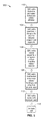
- FIG. 5 is a flow diagram of a coating process in accordance with the technology of the present disclosure.
- FIG. 6 is a schematic diagram of a deposition system in accordance with the technology of the present disclosure.
- system and methods of the technology of the present disclosure are directed to atomized polymer deposition directly onto the surface of a Guglielmi Detachable Coil (GDC).
- GDC Guglielmi Detachable Coil
- the polymer or combination of polymers is first solvated into a non-viscous solution.
- the GDC is elongated, along the coil axis, to create a linear target.
- the systems and methods of the technology of the present disclosure employ atomization techniques which can be separated into two key components: droplet breakup, and the influence of solvent evaporation.
- precise control of the atomized polymer particles is important. In general, discrete spiral coating can be achieved if atomized particles are smaller than the gap between adjacent coil segments
- FIG. 1 is a side view of a nozzle 10 and corresponding atomized deposition droplet breakdown 12 in accordance with the technology of the present disclosure.
- Droplet breakdown will be discussed first with reference to FIG. 1 .
- atomized particles exiting distal end of nozzle 20 undergo primary atomization at region 14 that extends distance D 1 from the nozzle exit 20 .
- the solution flow causes solution to exit the atomization nozzle 10 , and dispensing air pressure causes initial breakup.
- droplets are considered to be “immature,” having a high solvent content and generally comprising large droplets (e.g. droplet 40 shown in FIG. 2A ).
- the secondary atomization region comprises two sub-regions: 1) an optimal droplet zone 16 spanning from D 1 to distance D 2 from the nozzle exit 20 , and 2) low-solvent region 18 extending beyond distance D 2 from the nozzle exit 20 .
- immature droplets break down further into smaller droplets (e.g. droplet 42 of FIG. 2A ).
- the other influential component of atomization involves the influence of solvent evaporation. Over time, solvent will evaporate. For an individual atomized particle, the longer time-of-flight a particle has, the more solvent will be removed from that particle. Particles begin as large and high solvent content droplets (primary atomization region 14 ), transition to smaller droplets with lower solvent content (optimal droplet region 16 ), and lastly transition to even smaller and tacky polymer spheres (low-solvent content region 18 ). For this reason, particles in the secondary atomization region, and in particular, the optimal droplet zone 16 that contains small particles and sufficient solvent to spread on the coil surface, are utilized for the discrete spiral coating of the technology of the present disclosure.
- atomization is configured such that the droplets display low viscosity and low surface tension with respect to the coil material.
- the amount/concentration of solvent will generally control viscosity, which scales with surface tension. For example, for the same polymer-solvent system, more solvent would lower viscosity and surface tension, which produce better spreading and adhesion to substrate.
- the reservoir of the sprayer may also be heated to decrease viscosity, surface tension, and also make finer droplets because of faster solvent evaporation. Increasing the air-liquid flow ratio will also increase evaporation and make smaller droplets, but without thermal energy the viscosity and surface tension would increase. Since wetting is the final desired result, in a preferred embodiment the droplet in the optimized zone 16 is ideally configured to produce a wetting angle of less than 30 degrees on the coil substrate.
- FIG. 2A through FIG. 2C illustrate the importance of droplet size control and coil stretching with respect to GDC 30 .
- Spiral coating by atomized polymer deposition can be created using any GDC size, and thus the scale bar is provided for reference only.
- GDC 30 is not stretched (e.g. groove having spacing g r ).
- Sphere 40 represents a large, non-optimal droplet which will cover and occlude the helical gap or grooves of the GDC coil 30 and will not produce a discrete spiral coating.
- “occlusion” of the helical gap refers to a continuous or semi-continuous coating layer across the helical gap so as to close off the gap from one segment 32 to an adjacent segment, which may result in binding the coil 30 to restrict motion of the coil segments with respect to each other.
- Sphere 42 represents a small optimal droplet, in accordance with droplets disposed within optimal droplet zone 16 of FIG.
- the grooves of the GDC coil may still be occluded, even with the smaller droplet size 42 .
- the GDC coil 30 is stretched via application of tensile force F along the coil axis to increase the distance g s between adjacent coil segments 32 to create a linear target for deposition, as well as increase the gap between adjacent wire segments 32 to thereby increase coating efficiency for discrete spiral coating outer surface 34 .
- the vast majority of the deposited coating is restricted to outer surface 34 , leaving the inner surface 36 with a minimal amount of coating.
- a mandrel 38 may optionally be inserted down the center of coil 30 to further mask internal surface 36 from deposition.
- FIG. 3A through FIG. 3B illustrate cross-sectional views of coil 30 through various stages of the coating process of the technology of the present disclosure.
- FIG. 3A shows a view of the uncoated coil 30 showing only the metallic of coil segments 32 .
- FIG. 3B illustrates the outside surface of segments 32 coated with bioactive polymer layer 50 .
- inner surface 54 is substantially free of coating.
- FIG. 3B illustrates the outside surface of segments 32 coated with bioactive polymer layer 50 and lubricant layer 52 . Again, inner surface 54 is substantially free of coating.
- FIG. 4A shows a SEM image of an uncoated GDC 30 .
- FIG. 4B shows a SEM image of the coated GDC 30 with bioactive polymer 50 in accordance with the processes of the technology of the present disclosure.
- the coating is smooth, homogenous, even, and covers the exterior of the metallic surface, leaving the helical grooves/gap substantially free from occlusion of the polymer, i.e. devoid of polymer.
- FIG. 5 is a flow diagram of a coating process 100 in accordance with the technology of the present disclosure.
- Method 100 may be used in conjunction with deposition system 150 shown in FIG. 6 for the coating of a target such as GDC 30 .
- the coil 30 is optionally pretreated, e.g. with a cleansing solution, to increase polymer adhesion.
- the coils 32 of GDC 30 are stretched elastically along the coil axis at step 104 , as shown in FIG. 2B . Doing so creates a linear target, as well as increases the gap g s between adjacent coil segments 32 .
- step 106 the external surface 34 of coil 30 is discretely coated sequentially using a non-viscous bioactive polymer solution 162 ( FIG. 6 ).
- Parameters which influence discrete spiral coating include: solution viscosity, solvent evaporation rate, spray distance away from target (e.g. within optimal droplet zone 16 ), and rate of polymer deposition.
- Factors which influence particle size are: solution surface tension, dispensing air pressure, solution flow rate, deposition rate, and atomization technique employed. By manipulating these variables, atomized polymer droplets 42 can be created small enough such that these particles are smaller than the gaps between adjacent wire segments 32 .
- a 1% acidic 50:50 PLGA solution 162 in acetone (w/w) is created.
- the following solution dispensing parameters may be used using conventional air-assisted atomization:
- Airbrush-to-target distance 2 cm to 5 cm (e.g. distance D 1 to D 2 from nozzle exit 20 ),
- Angular tilting in x-y-z, and use of hydraulic airbrushes may also be considered. It is appreciated that the above parameters are variable, and may vary according to deposition technique, solution, coil size, etc.
- the solution 162 is then loaded into one or more airbrushes 160 (e.g. an array of 3 airbrushes) attached to a robotic polymer atomizing robot (x-y-z control 158 ).
- the robot 158 is controlled by a computer 152 having a processor 154 and programming 156 executable on the processor to modulate solution flow rate, deposition rate (controlled by vertical velocity along the coil axis), and the number of layers.
- the robot 158 can be mechanically modified to control droplet time-of-flight by moving the airbrush 160 closer to or away from the target 30 .
- ultrasonic atomization may also be used to achieve the discrete spiral coating of step 106 by modulating additional parameters specific to the ultrasonic atomization process: e.g. amplitude and frequency.
- polymer is imparted onto the GDC surface 34 in incremental layers. However, it is important to note that before a subsequent layer is deposited, the previous layer should be allowed to dry for a short period of time before the next layer is deposited.
- Post processing steps may also be applied to the coil surface to improve final polymer characteristics which include: polymer smoothness, discrete coil coating, and polymer durability.
- drying the polymer surface can be achieved at step 108 with heated or unheated air, infrared heat, or reducing surrounding air pressure.
- Discrete spiral coating can be maintained up to 20 ⁇ m in thickness by utilizing atomized polymer deposition. However, using thinner polymer layers is preferred to maintain coil flexibility and limit polymer fragmentation. A sacrificial gap layer may also be incorporated.
- the coils 30 are then transferred to an oven set at 37° C. and allowed to dry overnight. Coils 30 are then heat set above their glass transition temperature for a short period.
- the heat setting step 108 performs two primary functions. The first is to create a smooth surface due to stray particles by the atomization process. The second is to improve polymer hardness, by alignment of crystalline regions.
- a protective/lubricant polymer layer 52 may be deposited at step 110 such that the PLGA layer is protected during handling and delivery.
- Protective or lubricant coatings 52 may be in liquid state or solid state, but also preserve coil flexibility during deployment.
- Exemplary lubricants include, but are not limited to: hypromellose, carboxymethyl cellulose, Eudragit S 100 , etc.
- Final polymer characteristics may be improved at step 112 by radiation treatment to induce polymer cross-linking and provide sterilization.
- Gamma radiation may be used to increase polymer hardness and to address other handling and durability characteristics.
- Irradiation may also comprise electron beam, UV, or other sources available in the art.
- an endovascular device comprises a metallic spiral coil 30 and a coating 50 on the coil wherein the coating is formed on the outer surface 34 of the spiral coil only such that the grooves of the coil remain uncoated and substantially free of the coating.
- the metallic spiral coil 30 comprises platinum, tungsten, titanium, silver, stainless steel, zirconium, or an alloy thereof. In some embodiments, the metallic spiral coil 30 comprises Nitinol, polymers, or a biodegradable metal or alloy (e.g., magnesium or an alloy thereof).
- the coating 50 comprises a bioabsorbable polymer or a biodurable polymer.
- the bioabsorbable polymer comprises a polyester polymer, e.g., polyglycolic acid (PGA), poly-L-lactic acid (PLLA), polycaprolactive, poly-L-lactide, polydioxanone, polycarbonates, polyanhydrides, polyglycolic acid/poly-L-lactic acid copolymers, and polyhydroxybutyrate/hydroxyvalerate copolymers, or combinations thereof.
- the biodurable polymer comprises polyacrylate, polymethacrylate, polyether, or a fluorinated polymer.
- the polymer can be polylactone, poly-alpha-hydroxy acids, poly(3-hydroxyalkanoates), polyglycols, polytyrosine carbonates, starch, gelatins, cellulose as well as blends and interpolymers containing these components.
- poly-alpha-hydroxy acids are polylactides, polyglycol acids, and their interpolymers.
- the polymer can be caprolactone/glycolide copolymer or calcium stearoyl lactylate. Calcium stearoyl lactylate degrades into stearic and lactic acids.
- the polymer can also be acidic polyesters, such as a mixture of PLGA and hydroxyacetic acid (about equivalent molar ratios), or polyester anhydrides such as glycolic acid, lactic acid, or sebacic acid polymers.
- the coating 50 further comprises a bioactive agent.
- the coating 50 comprises a drug matrix layer comprising a bioactive agent, an optional primer layer underneath the drug matrix layer, and an optional a top layer immediately over the drug matrix layer, and wherein the optional top layer provides a controlled release of the bioactive agent.
- the coating 50 further comprises a biobeneficial material that enhances biocompatibility of the coating.
- biobeneficial material can be any material capable of enhancing biocompatibility of the coating.
- examples of such biobeneficial material can be, e.g., a material that comprises choline, e.g., phosphoryl choline.
- the various above embodiments of the endovascular device can be any endovascular device.
- the device is a detachable aneurysm coil.
- the device is a bare platinum coil.
- a method of forming a coating on an endovascular device comprises a spiral coil body.
- the method comprises: forming a primary layer on the coil using a first solution comprising a primary layer material in a first solvent; removing the primary layer from the grooves of the spiral coil; forming a second layer on the outer surface of the spiral coil; using a second solution comprising a second layer material and a second solvent; drying the second layer; removing the primary layer from the grooves of the spiral coil; and drying the coating; wherein the primary layer material does not dissolve in the second solution and is not wet well by the second solution; and wherein the coating covers only the outer surface of the spiral coil.
- Some embodiments of the method further comprise treating the coating with a solvent vapor to produce a smooth even coating.
- an additional lubricant layer may be deposited on top of the second polymer layer, which imparts additional advantages or desirable properties to the coating, e.g., to prevent damage to the polymer layer during storage, to confer polymer integrity during deployment, and/or to decrease friction during deployment.
- the lubricant layer can also contain pro-inflammatory factors embedded within the lubricant layer, or possess inherent pro-inflammatory properties.
- any combination of solvents can be used for the first or second solvent as long as they do not mix together, which is shown by high interfacial tensions and present disparate solubility parameters.
- the solvents must dissolve their respective polymers.
- the only first solvent we have tested was water.
- Second solvents that we have tested were: 1,2 Dichloroethane, 2-Phenoxyethanol, Acetone, Acetonitrile, Benzaldehyde, Benzonitrile, Benzyl alcohol, Chloroform, Dichloromethane, Dimethyl Adipate, Dimethyl sulfoxide, Dimethylformamide, Dioxane, Ethyl acetate, Hexafluoroisopropanol, Propylene carbonate.
- First and second solvents were chosen based on similar Hansen solubility parameters as the primary or secondary polymer, respectively.
- the first solvent is water
- the second solvent is chloroform.
- the primary layer material is dextran sulfate.
- Other materials for the primary layer material can be, e.g., polyethylene glycol, polyvinyl Alcohol, polyacrylic acid, polyvinylpyrrolidone, polyacrylamide, carboxymethyl cellulose, guar gum, hypromellose, glucose, polyvinyl sulfate, polyvinyl phosphonic acid, mowiol, hydroxyethyl cellulose, dextran, dextran sulfate, glycolide, pullan, starch, xylan, polyallylamie, polyepoxysuccinic acid, amylose, galactan, cellulose, gelatin, pectin, chitosan.
- the second layer material comprises a bioabsorbable polymer or a biodurable polymer.
- the bioabsorbable polymer comprises a polyester, e.g., poly(lactic acid) (PLA), poly(lactic-co-glycolic acid) (PLGA), or a combination thereof.
- the biodurable polymer comprises polyacrylate, polymethacrylate, polyether, or a fluorinated polymer.
- the polymer can be polylactone, poly-alpha-hydroxy acids, poly(3-hydroxyalkanoates), polyglycols, polytyrosine carbonates, starch, gelatins, cellulose as well as blends and interpolymers containing these components.
- poly-alpha-hydroxy acids examples include polylactides, polyglycol acids, and their interpolymers.
- the polymer can be caprolactone/glycolide copolymer or calcium stearoyl lactylate. Calcium stearoyl lactylate degrades into stearic and lactic acids.
- the second layer polymer comprises a material that generates a transient and mild inflammation so as to accelerate wound healing.
- pro-inflammatory coating materials are acidic polyesters which are examples of pro-inflammatory coating materials that can accelerate healing.
- the polymer can also be acidic polyesters, such as a mixture of PLGA and hydroxyacetic acid (about equivalent molar ratios), or polyester anhydrides such as glycolic acid, lactic acid, or sebacic acid polymers.
- the coating may contain fillers or particles that happen to cause transient and mild inflammation.
- the various features of the spiral coil including the polymer, the coating, the layers of coating, and the bioactive agent are as described above or below.
- the various above embodiments of the endovascular device can be any endovascular device.
- the device is a detachable aneurysm coil.
- the device is a bare platinum coil.
- a method of forming a coating on a spiral coil comprises pre-stretching and without pre-stretching techniques such as rolling, spraying, stamping, printing, etc.
- Other coating techniques include: direct dip coating, roll coating, spray coating, and geometric printing. All of these techniques—including the technique described above and below—may require the spiral coil to be stretched along the coil axis, prior to the coating methods, to expose the grooves such that the final coating is deposited exclusively on the coil surface.
- Direct dip coating a spiral coil is immersed in a polymer solution (with appropriate solvent), withdrawn from the solution, and allowed to dry.
- Roll coating bioactive polymer is applied to a flat rubber stamping device.
- the bioactive polymer is applied to the spiral coil by touching the rubber stamp to an elongated spiral coil.
- the rubber stamp moves linearly along the coil, such that it rolls the coil. During this motion, the polymer releases from the rubber stamp, and is applied to the spiral coil.
- Spray coating a solution of bioactive polymer is prepared and is deposited onto the spiral coil surface by atomization. This process is similar to airbrushing or spray painting.
- the method comprises an optional step.
- This step will precede all coating steps.
- This step pertains to direct modification of the metal surface such that it increases the adhesion of the polymer to the metal surface.
- This technique can be achieved by increasing the surface area of the spiral coil, or increasing wetting of the polymer solution to the metal surface.
- Techniques to increase the surface area of the metal surface include: surface abrasion or acid etching.
- Techniques to increase the wetting of the polymer solution to the metal surface include plasma etching, plasma treatment, and surface cleaning.
- a method of treating or ameliorating a medical condition comprises implanting in a mammalian subject an endovascular device according to any of the various embodiments described above or below.
- the medical condition is intracranial aneurysm rupture.
- the technology of the present disclosure is advantageous in that it allows the modification of bare metallic coils (e.g., bare platinum coils) such that only selected surfaces along the spiral coil is coated with a polymer.
- This polymer coating can be bioactive, or may release a bioactive agent, or it may react with the local environment to provide bulking function. By leaving the grooves between each coil segment uncoated, the coating preserves the mechanical flexibility of the coil.
- the technology of the present disclosure can be applied to any currently available coil systems for the treatment of any medical condition that can be treated by an endovascular coil.
- An example of such medical conditions is brain aneurysms.
- the technology of the present disclosure will allow the coil material or system to have additional bioactive coating without impeding its mechanical property. Relatively large aneurysms will be treated more effectively so as to achieve less recanalization rate and improved treatment rate.
- the endovascular device provided herein is capable of generating a transient and mild inflammation condition at a site receiving the device or the surrounding area.
- a transient and mild inflammation condition can facilitate healing of a wound in a site receiving a device of the technology of the present disclosure.
- acid polyesters can be coated onto a device disclosed herein to generate transient and mild inflammation at the site receiving the device.
- an “effective amount” or “pharmaceutically effective amount” refer to a nontoxic but sufficient amount of the agent to provide the desired biological result. That result can be reduction and/or alleviation of the signs, symptoms, or causes of a disease, or any other desired alteration of a biological system.
- an “effective amount” for therapeutic uses is the amount of the composition comprising a drug disclosed herein required to provide a clinically significant modulation in the symptoms associated with vascular permeability.
- An appropriate “effective amount” in any individual case may be determined by one of ordinary skill in the art using routine experimentation.
- the terms “treat” or “treatment” are used interchangeably and are meant to indicate a postponement of development of a disease associated with vascular permeability and/or a reduction in the severity of such symptoms that will or are expected to develop.
- the terms further include ameliorating existing symptoms, preventing additional symptoms, and ameliorating or preventing the underlying metabolic causes of symptoms.
- polymer is defined as being inclusive of homopolymers, copolymers, and oligomers.
- homopolymer refers to a polymer derived from a single species of monomer.
- copolymer refers to a polymer derived from more than one species of monomer, including copolymers that may be obtained by copolymerization of two monomer species, those that may be obtained from three monomers species (“terpolymers”), those that may be obtained from four monomers species (“quaterpolymers”), etc.
- terpolymers those that may be obtained from three monomers species
- quadterpolymers those that may be obtained from four monomers species
- Some examples of polymers are bioabsorbable polymers and biodurable polymers.
- polymer includes any polymers that either directly, or indirectly by their degradation products will promote at least 25% increase in activities of neutrophils, macrophages, or other lymphocytes. Generally, such polymers do not include a polymer that tends to stick to itself when wet, as this would cause coil-coil friction during deployment and retrieval.
- the bioabsorbable polymer comprises a polyester, e.g., poly(lactic acid) (PLA), poly(lactic-co-glycolic acid) (PLGA), or a combination thereof or poly polyorthoesters.
- Bioabsorbable polymers can have acid, base, hydroxyl, or ester functional groups as side groups (pendant groups) or at one or both ends of the polymer backbone, which can also be referred to as acid-terminated, base-terminated, hydroxyl terminated, or ester terminated polymer.
- These polymers can be readily prepared according to established methodologies of polyester preparation. For example, acid terminated polyester can be readily prepared by using a diacid as the initiator in the preparation of the polyester.
- amine-terminated (base-terminated), hydroxyl-terminated or ester-terminated polyester polymers can be readily prepared using a diamine, diol or an ester having a free hydroxyl group initiator in the preparation of the bioabsorbable polymer (e.g., PLA, PLGA, polyorthoester), respectively.
- the bioabsorbable polymer e.g., PLA, PLGA, polyorthoester
- the bioabsorbable polymer includes polymers that break down into acidic/basic monomers (e.g., PLA or polyorthoesters). The degradation products of these polymers can cause slightly inflammatory reactions.
- the biodurable polymer comprises polyacrylate, polymethacrylate, polyether, or a fluorinated polymer.
- poly(lactic acid-co-glycolic acid) or “PLGA” refers to a copolymer formed by copolycondensation of lactic acid, HO—CH(CH 3 )—COOH, and glycolic acid, HO—CH 2 —COOH.
- the term “subject” encompasses mammals and non-mammals.
- mammals include, but are not limited to, any member of the Mammalian class: humans, non-human primates such as chimpanzees, and other apes and monkey species; farm animals such as cattle, horses, sheep, goats, swine; domestic animals such as rabbits, dogs, and cats; laboratory animals including rodents, such as rats, mice and guinea pigs, and the like.
- non-mammals include, but are not limited to, birds, fish and the like. The term does not denote a particular age or gender.
- substantially free is meant that at least 80% or more (e.g., 90% or more, 95% or more, or 99%) area of the grooves of the spiral coil remain uncoated. Conversely, in some embodiments, by “substantially free” is meant that at least 80% or more (e.g., 90% or more, 95% or more, or 99%) area of the outer surface of the spiral coil remains uncoated.
- the primary layer material has a solubility in the second solvent of lower than 1 g/100 cc.
- the primary layer and the second solution has a contact angle ( ⁇ ) that is 90° or larger ( ⁇ 90°).
- the contact angle is the angle at which the liquid-vapor interface meets the solid-liquid interface.
- the contact angle is determined by the resultant between adhesive and cohesive forces. As the tendency of a drop to spread out over a flat, solid surface increases, the contact angle decreases. Thus, the contact angle provides an inverse measure of wettability. Adhesive forces between a liquid and solid cause a liquid drop to spread across the surface. Cohesive forces within the liquid cause the drop to ball up and avoid contact with the surface.
- biologically active agent can be any biologically active molecule. Any biologically active substance can be used as the source of biologically active molecules. Representative examples include laminin and growth factors such as IGF (insulin-like growth factors), TGF (transforming growth factors), FGB (fibroblast growth factors), including b-FGF (basic fibroblast growth factors), EGF (epidermal growth factors), VEGF (vascular endothelial growth factors), BMP (bone morphogenic proteins), PDGF (platelet-derived growth factors), or combinations thereof. These growth factors are well known and are commercially available.
- IGF insulin-like growth factors
- TGF transforming growth factors
- FGB fibroblast growth factors
- b-FGF basic fibroblast growth factors
- EGF epidermal growth factors
- VEGF vascular endothelial growth factors
- BMP bone morphogenic proteins
- PDGF platelet-derived growth factors
- the term “coil” can be any type of coil known in the art, such as, for example, a Guglielmi detachable coil (GDC).
- GDC Guglielmi detachable coil
- the coil can be coated with an absorbable polymeric material to improve long-term anatomic results in the endovascular treatment of intracranial aneurysms.
- the coil can further be coated to decrease friction to decrease the granulation tissue formation around the coils.
- the coating comprises at least one biocompatible and bioabsorbable polymer and growth factors, and is used to accelerate histopathologic transformation of unorganized clots into fibrous connective tissue in aneurysms.
- solvent vapor generally refers to the vapor of a volatile solvent capable of dissolving a polymer for forming the second layer of a coating disclosed herein.
- the volatile solvent can be the same as or different from the solvent for the second solution for forming the second layer of coating.
- An example of the volatile solvent is acetone.
- Another example of the volatile solvent is ethyl acetate.
- transient and mild inflammation refers to an inflammatory condition limited to the site of tissue receiving a device disclosed herein and the surrounding area that would disappear or clear in a short period of time, e.g., hours or days. Such transient and mild inflammation is within the knowledge of a medical practitioner or researcher and can be measured by, e.g., a slight elevation of temperature (e.g., an increase of temperature of 0.5 F, 1 F, 1.5 F, or 2 F) at the site of tissue receiving the device and the surrounding area.
- a slight elevation of temperature e.g., an increase of temperature of 0.5 F, 1 F, 1.5 F, or 2 F
- the first step is performed by immersing the entire coil in an aqueous solution of dextran sulfate to form a primary layer, and then drawing the coil through a small aperture in a Teflon tape at controlled draw velocity to remove excess dextran sulfate.
- This first step confines the primary layer to the grooves of the coil.
- This dextran-coated coil is subsequently immersed and drawn from a polymer/chloroform solution (e.g., acid modified PLGA).
- the dextran sulfate can be replaced by any other polymer that does not dissolve in the second solution, and is not wet well by the second solution.
- the coil is immersed in water to remove the primary layer, and then dried. The coil is then flexed to remove any PLGA that has spanned over the grooves. Lastly the coil is exposed to acetone vapor to produce a smooth even coating which only covers the outer coil surface.
- An endovascular device comprising: a metallic spiral coil and a coating on the coil; wherein the coating is formed only on the outer surface of the spiral coil such that the grooves of the coil remain uncoated and substantially free of the coating.
- the metallic spiral coil comprises platinum, tungsten, titanium, silver, stainless steel, zirconium, or an alloy thereof.
- the coating comprises a bioabsorbable polymer or a biodurable polymer.
- the coating further comprises a bioactive agent.
- the coating comprises a drug matrix layer comprising a bioactive agent, an optional primer layer underneath the drug matrix layer, and an optional top layer immediately over the drug matrix layer, and wherein the optional top layer provides a controlled release of the bioactive agent.
- the coating comprises a bioabsorbable polymer selected from the group consisting of poly(lactic acid) (PLA), poly(lactic-co-glycolic acid) (PLGA), or a combination thereof, or a biodurable polymer selected from the group consisting of polyacrylate, polymethacrylate, polyether, or a fluorinated polymer.
- a bioabsorbable polymer selected from the group consisting of poly(lactic acid) (PLA), poly(lactic-co-glycolic acid) (PLGA), or a combination thereof, or a biodurable polymer selected from the group consisting of polyacrylate, polymethacrylate, polyether, or a fluorinated polymer.
- the coating comprises a biobeneficial material that enhances biocompatibility of the coating.
- the coating comprises a pro-inflammatory material that generates a transient and mild inflammation.
- the coating comprises an acid polyester or a filler material or particles.
- the coating comprises a lubricant layer deposited on top of a polymer layer.
- the coating comprises a lubricant layer deposited on a polymer layer, and wherein a pro-inflammatory material is embedded within the lubricant layer.
- the coating includes a lubricant layer that possesses inherent pro-inflammatory properties.
- a method of forming a coating on an endovascular device comprising a spiral coil body, the method comprising: forming a primary layer on the coil using a first solution comprising a primary layer material in a first solvent, removing the primary layer from the grooves of the spiral coil or the outer surface of the spiral coil, forming a second layer on the grooves of the spiral coil or on the outer surface of the spiral coil using a second solution comprising a second layer material and a second solvent, drying the second layer, removing the primary layer from the grooves of the spiral coil or the outer surface of the spiral coil, and drying the coating, wherein the primary layer material does not dissolve in the second solution and is not wet well by the second solution, and wherein the coating covers only the outer surface of the spiral coil.
- the primary layer material is dextran sulfate
- the second layer material is a poly(lactic acid) (PLA), poly(lactic acid-co-glycolic acid) (PLGA), or a combination thereof.
- spiral coil is a metallic spiral coil comprising platinum, tungsten, titanium, silver, stainless steel, zirconium, or an alloy thereof.
- the second layer comprises a bioabsorbable polymer or a biodurable polymer.
- the second layer further comprises a bioactive agent.
- the coating comprises a drug matrix layer comprising a bioactive agent, an optional primer layer underneath the drug matrix layer, and an optional a top layer immediately over the drug matrix layer, wherein the second layer is the drug matrix layer, and wherein the optional top layer provides a controlled release of the bioactive agent.
- the coating comprises a bioabsorbable polymer selected from the group consisting of poly(lactic acid) (PLA), poly(lactic-co-glycolic acid) (PLGA), or a combination thereof, or wherein the coating comprises a biodurable polymer selected from the group consisting of polyacrylate, polymethacrylate, polyether, or a fluorinated polymer.
- PLA poly(lactic acid)
- PLGA poly(lactic-co-glycolic acid)
- the coating comprises a biodurable polymer selected from the group consisting of polyacrylate, polymethacrylate, polyether, or a fluorinated polymer.
- the coating comprises a biobeneficial material that enhances biocompatibility of the coating.
- the coating comprises a pro-inflammatory material that generates a transient and mild inflammation.
- the coating comprises an acid polyester or a filler material or particles.
- the coating comprises a lubricant layer on top of a polymer layer.
- the coating includes a lubricant layer that possesses inherent pro-inflammatory properties.
- the endovascular device is a detachable aneurysm coil.
- a method of treating or ameliorating a medical condition comprising implanting in a mammalian subject in need thereof an endovascular device according to any previous embodiment.
- a method of forming a coating on an endovascular spiral coil having a plurality of coil segments each separated by a helical gap comprising: providing a solution comprising a polymeric coating; atomizing the polymeric coating a into a plurality of droplets at a set distance from the spiral coil; and coating an external surface of the spiral coil with the plurality of polymeric coating droplets; wherein the droplets have a size smaller than the helical gap separating the plurality of coil segments such that internal surfaces with respect to the helical gap remain substantially free of occlusion by the polymeric coating.
- the method further comprising: prior to coating the external surface, applying an axial tensile load on the spiral coil to expand the helical gap between the plurality of coil segments to an expanded distance greater than the resting gap distance.
- the polymeric layer comprises a bioactive agent configured to promote wound healing.
- a method of forming a coating on an endovascular spiral coil, the spiral coil having a plurality of coil segments each separated by a helical gap comprising: providing a solution comprising a polymeric coating; atomizing the polymeric coating into a plurality of droplets at a set distance from the spiral coil; wherein the helical gap comprises a resting gap distance when disposed in an unloaded state; applying an axial tensile load on the spiral coil to expand the helical gap between the plurality of coil segments to an expanded distance greater than the resting gap distance; and coating an external surface of the spiral coil with the plurality of polymeric coating droplets; wherein the droplets have a size smaller than the expanded helical gap distance separating the plurality of coil segments such that internal surfaces with respect to the helical gap remain substantially free of occlusion by the polymeric coating.
- the polymeric layer comprises a bioactive agent configured to promote wound healing.
- a system for generating a coating on an endovascular spiral coil having a plurality of coil segments each separated by a helical gap comprising: a deposition nozzle for receiving a solution comprising a polymeric coating; the deposition nozzle configured for atomizing the polymeric coating into a plurality of droplets at a set distance from the spiral coil; the deposition nozzle further configured for coating an external surface of the spiral coil with the plurality of polymeric coating droplets; an actuator coupled to the deposition nozzle for modifying the set distance from the nozzle to the spiral coil; a processor coupled to the actuator and deposition nozzle; and programming executable on the processor for: adjusting position and deposition characteristics of the deposition nozzle to adjust the size of the plurality of droplets to have a size smaller than the helical gap separating the plurality of coil segments.
- the programming is further configured for: adjusting the size of the plurality of droplets by controlling one or more of: solution viscosity, solvent evaporation rate, distance from the spiral coil, rate of polymer deposition; solution surface tension, deposition air pressure, solution flow rate, and deposition rate.
Landscapes
- Materials For Medical Uses (AREA)
- Physics & Mathematics (AREA)
- Engineering & Computer Science (AREA)
- Plasma & Fusion (AREA)
Abstract
Systems and methods for coating of spiral intracranial aneurysm coils, e.g., a Guglielmi Detachable Coil (GDC), such that only selected surfaces along the spiral coil are coated with a polymer via an atomized polymer deposition process. The resulting device is a detachable aneurysm coil system which preserves the mechanical geometry and flexibility of the coil, and delivers specific agents to promote wound healing.
Description
This application is a 35 U.S.C. §111(a) continuation of PCT international application number PCT/US2013/047713 filed on Jun. 25, 2013, incorporated herein by reference in its entirety, which claims priority to, and the benefit of, U.S. provisional patent application Ser. No. 61/691,244 filed on Aug. 20, 2012, incorporated herein by reference in its entirety. PCT international application number PCT/US2013/047713 filed on Jun. 25, 2013 is a continuation-in-part of PCT international application serial number PCT/US2012/044049 filed on Jun. 25, 2012 and published as PCT International Publication No. WO 2013/006298 A2 on Jan. 10, 2013, incorporated herein by reference in its entirety. PCT international application serial number PCT/US2012/044049 filed on Jun. 25, 2012 claims priority to, and the benefit of, U.S. provisional patent application Ser. No. 61/505,470 filed on Jul. 7, 2011, incorporated herein by reference in its entirety. Priority is claimed to each of the foregoing applications.
PCT international application number PCT/US2013/047713 filed on Jun. 25, 2013 was published as PCT International Publication No. WO 2014/004579 on Jan. 3, 2014, which publication is incorporated herein by reference in its entirety.
Not Applicable
Not Applicable
A portion of the material in this patent document is subject to copyright protection under the copyright laws of the United States and of other countries. The owner of the copyright rights has no objection to the facsimile reproduction by anyone of the patent document or the patent disclosure, as it appears in the United States Patent and Trademark Office publicly available file or records, but otherwise reserves all copyright rights whatsoever. The copyright owner does not hereby waive any of its rights to have this patent document maintained in secrecy, including without limitation its rights pursuant to 37 C.F.R. §1.14.
1. Technical Field
This technology relates generally to a bioactive coating on a medical device and methods of making and using the same, and more particularly to an intracranial aneurysm coil having a polymer coating on selected surfaces of the coil.
2. Background Discussion
Subarachnoid hemorrhage from intracranial aneurysm rupture remains a devastating disease. Endovascular occlusion of ruptured and unruptured intracranial aneurysms using Guglielmi Detachable Coil (GDC) technology has gained worldwide acceptance as a less-invasive treatment alternative to standard microsurgical clipping. However, critical evaluation of the long-term anatomical results of aneurysms treated with metal coils shows three limitations. First, compaction and aneurysm recanalization can occur. This technical limitation is more often seen in small aneurysms with wide necks and in large or giant aneurysms. Second, the standard platinum metal coil is relatively biologically inert. Research relating to methods of enhancing the biological activity of metal coils highlights the increased interest in finding innovative solutions to overcome these present biological limitations of the conventional metal coil system.
Polymeric coatings carrying a bioactive agent have been used to impart bioactivity to implantable devices (e.g., stents). However, when a polymeric coating is formed on a spiral coil, often times, the grooves of the spiral coil are coated along with the outer surface of the coil, causing the mechanical flexibility to be compromised, which is undesirable. Further, for a spiral coil to be spatially compatible with a vascular lumen in the brain, sometimes it is important to limit the diameter of a coil to a certain size since it is constrained by the inner diameter of the microcatheter used for placing the coil.
The technology of the present disclosure addresses the foregoing limitations of spiral intracranial aneurysm coils.
An aspect of this technology of the present disclosure comprises systems and methods for coating of spiral intracranial aneurysm coils, e.g., a Guglielmi Detachable Coil (GDC), such that only selected surfaces along the spiral coil are coated with a polymer via an atomized polymer deposition process. The resulting device is detachable aneurysm coil system which preserves the mechanical properties, flexibility, low friction, etc. to allow delivery, and low coil-coil entanglement to allow re-positioning of the coil, and delivers specific agents to promote wound healing.
The coated polymer coating may be bioactive, or may release a bioactive agent, or it may be of a type that reacts with the local environment to provide bulking function. Unlike liquid embolic agents, such as Onyx, which cannot be controlled in the context of placement or three dimensional shape, the coating material and processes of the technology of the present disclosure can be selected to remain in a solid state with defined shape and dimension for precise and accurate placement within the target.
This technology is compatible with existing coils (e.g. GDC's), which are already familiar to practitioners in the field. The technology of the present disclosure preserves the mechanical handling of existing coils, while adding a bioactive agent. To preserve the flexibility and deliver specific agents to promote wound healing, the coating process of the technology of the present disclosure minimizes and confines the location of the polymer coating layer such that it does not impede the coils flexibility. By leaving the grooves between each coil segment uncoated, the coating preserves the mechanical flexibility of the coil.
The polymer coating of the technology of the present disclosure provides two primary functions: to promote wound healing through intrinsic polymer properties, and to provide a potential vehicle for drug delivery. In addition, by employing post-processing techniques, the polymeric surface is improved to limit friction and wear of the coated surface.
Further aspects of the technology will be brought out in the following portions of the specification, wherein the detailed description is for the purpose of fully disclosing preferred embodiments of the technology without placing limitations thereon.
The technology of the present disclosure will be more fully understood by reference to the following drawings which are for illustrative purposes only:
In a preferred embodiment, the system and methods of the technology of the present disclosure are directed to atomized polymer deposition directly onto the surface of a Guglielmi Detachable Coil (GDC).
The polymer or combination of polymers is first solvated into a non-viscous solution. The GDC is elongated, along the coil axis, to create a linear target. The systems and methods of the technology of the present disclosure employ atomization techniques which can be separated into two key components: droplet breakup, and the influence of solvent evaporation. In order to achieve discrete spiral coating along the coil, precise control of the atomized polymer particles is important. In general, discrete spiral coating can be achieved if atomized particles are smaller than the gap between adjacent coil segments
Droplet breakdown will be discussed first with reference to FIG. 1 . Initially, atomized particles exiting distal end of nozzle 20 undergo primary atomization at region 14 that extends distance D1 from the nozzle exit 20. The solution flow causes solution to exit the atomization nozzle 10, and dispensing air pressure causes initial breakup. In the primary atomization region 14, droplets are considered to be “immature,” having a high solvent content and generally comprising large droplets (e.g. droplet 40 shown in FIG. 2A ).
After primary atomization, secondary atomization takes place beyond distance D1 from the nozzle exit 20. The secondary atomization region comprises two sub-regions: 1) an optimal droplet zone 16 spanning from D1 to distance D2 from the nozzle exit 20, and 2) low-solvent region 18 extending beyond distance D2 from the nozzle exit 20. In region 16, immature droplets break down further into smaller droplets (e.g. droplet 42 of FIG. 2A ).
The other influential component of atomization involves the influence of solvent evaporation. Over time, solvent will evaporate. For an individual atomized particle, the longer time-of-flight a particle has, the more solvent will be removed from that particle. Particles begin as large and high solvent content droplets (primary atomization region 14), transition to smaller droplets with lower solvent content (optimal droplet region 16), and lastly transition to even smaller and tacky polymer spheres (low-solvent content region 18). For this reason, particles in the secondary atomization region, and in particular, the optimal droplet zone 16 that contains small particles and sufficient solvent to spread on the coil surface, are utilized for the discrete spiral coating of the technology of the present disclosure.
In a preferred configuration, atomization is configured such that the droplets display low viscosity and low surface tension with respect to the coil material. The amount/concentration of solvent will generally control viscosity, which scales with surface tension. For example, for the same polymer-solvent system, more solvent would lower viscosity and surface tension, which produce better spreading and adhesion to substrate. Incidentally, the reservoir of the sprayer may also be heated to decrease viscosity, surface tension, and also make finer droplets because of faster solvent evaporation. Increasing the air-liquid flow ratio will also increase evaporation and make smaller droplets, but without thermal energy the viscosity and surface tension would increase. Since wetting is the final desired result, in a preferred embodiment the droplet in the optimized zone 16 is ideally configured to produce a wetting angle of less than 30 degrees on the coil substrate.
In FIG. 2A , GDC 30 is not stretched (e.g. groove having spacing gr). Sphere 40 represents a large, non-optimal droplet which will cover and occlude the helical gap or grooves of the GDC coil 30 and will not produce a discrete spiral coating. For purposes of this description, “occlusion” of the helical gap refers to a continuous or semi-continuous coating layer across the helical gap so as to close off the gap from one segment 32 to an adjacent segment, which may result in binding the coil 30 to restrict motion of the coil segments with respect to each other. Sphere 42 represents a small optimal droplet, in accordance with droplets disposed within optimal droplet zone 16 of FIG. 1 , that are configured to more likely produce a discrete spiral coating on the outer surface 34 of the individual segments 32 of coil 30. Based on the resting gap/groove size gr, the grooves of the GDC coil may still be occluded, even with the smaller droplet size 42.
In accordance with a preferred method of the technology of the present disclosure illustrated in FIG. 2B , the GDC coil 30 is stretched via application of tensile force F along the coil axis to increase the distance gs between adjacent coil segments 32 to create a linear target for deposition, as well as increase the gap between adjacent wire segments 32 to thereby increase coating efficiency for discrete spiral coating outer surface 34. Generally, the vast majority of the deposited coating is restricted to outer surface 34, leaving the inner surface 36 with a minimal amount of coating.
As shown in FIG. 2C , a mandrel 38 may optionally be inserted down the center of coil 30 to further mask internal surface 36 from deposition.
First, at block 102, the coil 30 is optionally pretreated, e.g. with a cleansing solution, to increase polymer adhesion.
In a preferred embodiment, the coils 32 of GDC 30 are stretched elastically along the coil axis at step 104, as shown in FIG. 2B . Doing so creates a linear target, as well as increases the gap gs between adjacent coil segments 32.
Next, at step 106, the external surface 34 of coil 30 is discretely coated sequentially using a non-viscous bioactive polymer solution 162 (FIG. 6 ).
Parameters which influence discrete spiral coating include: solution viscosity, solvent evaporation rate, spray distance away from target (e.g. within optimal droplet zone 16), and rate of polymer deposition.
Factors which influence particle size are: solution surface tension, dispensing air pressure, solution flow rate, deposition rate, and atomization technique employed. By manipulating these variables, atomized polymer droplets 42 can be created small enough such that these particles are smaller than the gaps between adjacent wire segments 32.
In one embodiment, a 1% acidic 50:50 PLGA solution 162 in acetone (w/w) is created. In one embodiment, the following solution dispensing parameters may be used using conventional air-assisted atomization:
(a) Air Pressure: 15 PSI to 25 PSI,
(b) Solution flow rate per airbrush: 0.001 g/s to 0.01 g/s,
(c) Airbrush-to-target distance: 2 cm to 5 cm (e.g. distance D1 to D2 from nozzle exit 20),
(d) Translational velocity: 1 cm/s to 10 cm/s.
Angular tilting (in x-y-z, and use of hydraulic airbrushes may also be considered. It is appreciated that the above parameters are variable, and may vary according to deposition technique, solution, coil size, etc.
The solution 162 is then loaded into one or more airbrushes 160 (e.g. an array of 3 airbrushes) attached to a robotic polymer atomizing robot (x-y-z control 158). The robot 158 is controlled by a computer 152 having a processor 154 and programming 156 executable on the processor to modulate solution flow rate, deposition rate (controlled by vertical velocity along the coil axis), and the number of layers. The robot 158 can be mechanically modified to control droplet time-of-flight by moving the airbrush 160 closer to or away from the target 30.
In one embodiment, ultrasonic atomization may also be used to achieve the discrete spiral coating of step 106 by modulating additional parameters specific to the ultrasonic atomization process: e.g. amplitude and frequency.
Using these parameters, polymer is imparted onto the GDC surface 34 in incremental layers. However, it is important to note that before a subsequent layer is deposited, the previous layer should be allowed to dry for a short period of time before the next layer is deposited.
Post processing steps may also be applied to the coil surface to improve final polymer characteristics which include: polymer smoothness, discrete coil coating, and polymer durability.
In one embodiment, drying the polymer surface can be achieved at step 108 with heated or unheated air, infrared heat, or reducing surrounding air pressure.
The number of polymer layers deposited will dictate the final thickness. Discrete spiral coating can be maintained up to 20 μm in thickness by utilizing atomized polymer deposition. However, using thinner polymer layers is preferred to maintain coil flexibility and limit polymer fragmentation. A sacrificial gap layer may also be incorporated.
In one embodiment, after the coils have been coated, the coils 30 are then transferred to an oven set at 37° C. and allowed to dry overnight. Coils 30 are then heat set above their glass transition temperature for a short period. The heat setting step 108 performs two primary functions. The first is to create a smooth surface due to stray particles by the atomization process. The second is to improve polymer hardness, by alignment of crystalline regions.
Additional post-processing steps may be utilized to increase other polymer coating properties. A protective/lubricant polymer layer 52 may be deposited at step 110 such that the PLGA layer is protected during handling and delivery. Protective or lubricant coatings 52 may be in liquid state or solid state, but also preserve coil flexibility during deployment. Exemplary lubricants include, but are not limited to: hypromellose, carboxymethyl cellulose, Eudragit S100, etc.
Final polymer characteristics may be improved at step 112 by radiation treatment to induce polymer cross-linking and provide sterilization. Gamma radiation may be used to increase polymer hardness and to address other handling and durability characteristics. Irradiation may also comprise electron beam, UV, or other sources available in the art.
The technology of the present disclosure described in FIG. 1 through FIG. 6 above may also incorporate, or be combined with the inventive concepts and embodiments described in our prior PCT international patent application PCT/US2012/044049 filed on Jun. 25, 2012 and published as PCT International Publication No. WO 2013/006298 A2 on Jan. 10, 2013.
In one embodiment, an endovascular device comprises a metallic spiral coil 30 and a coating 50 on the coil wherein the coating is formed on the outer surface 34 of the spiral coil only such that the grooves of the coil remain uncoated and substantially free of the coating.
In some embodiments of the endovascular device, the metallic spiral coil 30 comprises platinum, tungsten, titanium, silver, stainless steel, zirconium, or an alloy thereof. In some embodiments, the metallic spiral coil 30 comprises Nitinol, polymers, or a biodegradable metal or alloy (e.g., magnesium or an alloy thereof).
In some embodiments of the endovascular device, optionally in combination with any or all of the above various embodiments, the coating 50 comprises a bioabsorbable polymer or a biodurable polymer. In some embodiments, the bioabsorbable polymer comprises a polyester polymer, e.g., polyglycolic acid (PGA), poly-L-lactic acid (PLLA), polycaprolactive, poly-L-lactide, polydioxanone, polycarbonates, polyanhydrides, polyglycolic acid/poly-L-lactic acid copolymers, and polyhydroxybutyrate/hydroxyvalerate copolymers, or combinations thereof.
In some embodiments, the biodurable polymer comprises polyacrylate, polymethacrylate, polyether, or a fluorinated polymer.
In some embodiments, the polymer can be polylactone, poly-alpha-hydroxy acids, poly(3-hydroxyalkanoates), polyglycols, polytyrosine carbonates, starch, gelatins, cellulose as well as blends and interpolymers containing these components. Examples of poly-alpha-hydroxy acids are polylactides, polyglycol acids, and their interpolymers.
In some embodiments, the polymer can be caprolactone/glycolide copolymer or calcium stearoyl lactylate. Calcium stearoyl lactylate degrades into stearic and lactic acids. The polymer can also be acidic polyesters, such as a mixture of PLGA and hydroxyacetic acid (about equivalent molar ratios), or polyester anhydrides such as glycolic acid, lactic acid, or sebacic acid polymers.
In some embodiments of the endovascular device, optionally in combination with any or all of the above various embodiments, the coating 50 further comprises a bioactive agent.
In some embodiments of the endovascular device, optionally in combination with any or all of the above various embodiments, the coating 50 comprises a drug matrix layer comprising a bioactive agent, an optional primer layer underneath the drug matrix layer, and an optional a top layer immediately over the drug matrix layer, and wherein the optional top layer provides a controlled release of the bioactive agent.
In some embodiments of the endovascular device, optionally in combination with any or all of the above various embodiments, the coating 50 further comprises a biobeneficial material that enhances biocompatibility of the coating. Such biobeneficial material can be any material capable of enhancing biocompatibility of the coating. Examples of such biobeneficial material can be, e.g., a material that comprises choline, e.g., phosphoryl choline.
The various above embodiments of the endovascular device can be any endovascular device. In some embodiments, the device is a detachable aneurysm coil. In some embodiments, the device is a bare platinum coil.
In another aspect of the technology of the present disclosure, there is provided a method of forming a coating on an endovascular device. The device comprises a spiral coil body. The method comprises: forming a primary layer on the coil using a first solution comprising a primary layer material in a first solvent; removing the primary layer from the grooves of the spiral coil; forming a second layer on the outer surface of the spiral coil; using a second solution comprising a second layer material and a second solvent; drying the second layer; removing the primary layer from the grooves of the spiral coil; and drying the coating; wherein the primary layer material does not dissolve in the second solution and is not wet well by the second solution; and wherein the coating covers only the outer surface of the spiral coil.
Some embodiments of the method further comprise treating the coating with a solvent vapor to produce a smooth even coating.
In some embodiments of the method, optionally in combination with any or all of the above various embodiments, an additional lubricant layer may be deposited on top of the second polymer layer, which imparts additional advantages or desirable properties to the coating, e.g., to prevent damage to the polymer layer during storage, to confer polymer integrity during deployment, and/or to decrease friction during deployment. In some embodiments, the lubricant layer can also contain pro-inflammatory factors embedded within the lubricant layer, or possess inherent pro-inflammatory properties.
In general any combination of solvents can be used for the first or second solvent as long as they do not mix together, which is shown by high interfacial tensions and present disparate solubility parameters. In addition, the solvents must dissolve their respective polymers. The only first solvent we have tested was water. Second solvents that we have tested were: 1,2 Dichloroethane, 2-Phenoxyethanol, Acetone, Acetonitrile, Benzaldehyde, Benzonitrile, Benzyl alcohol, Chloroform, Dichloromethane, Dimethyl Adipate, Dimethyl sulfoxide, Dimethylformamide, Dioxane, Ethyl acetate, Hexafluoroisopropanol, Propylene carbonate. First and second solvents were chosen based on similar Hansen solubility parameters as the primary or secondary polymer, respectively. In some embodiments of the method, the first solvent is water, and the second solvent is chloroform.
In some embodiments of the method, optionally in combination with any or all of the above various embodiments, the primary layer material is dextran sulfate. Other materials for the primary layer material can be, e.g., polyethylene glycol, polyvinyl Alcohol, polyacrylic acid, polyvinylpyrrolidone, polyacrylamide, carboxymethyl cellulose, guar gum, hypromellose, glucose, polyvinyl sulfate, polyvinyl phosphonic acid, mowiol, hydroxyethyl cellulose, dextran, dextran sulfate, glycolide, pullan, starch, xylan, polyallylamie, polyepoxysuccinic acid, amylose, galactan, cellulose, gelatin, pectin, chitosan. The second layer material comprises a bioabsorbable polymer or a biodurable polymer. In some embodiments, the bioabsorbable polymer comprises a polyester, e.g., poly(lactic acid) (PLA), poly(lactic-co-glycolic acid) (PLGA), or a combination thereof. In some embodiments, the biodurable polymer comprises polyacrylate, polymethacrylate, polyether, or a fluorinated polymer. In some embodiments, the polymer can be polylactone, poly-alpha-hydroxy acids, poly(3-hydroxyalkanoates), polyglycols, polytyrosine carbonates, starch, gelatins, cellulose as well as blends and interpolymers containing these components. Examples of poly-alpha-hydroxy acids are polylactides, polyglycol acids, and their interpolymers. In some embodiments, the polymer can be caprolactone/glycolide copolymer or calcium stearoyl lactylate. Calcium stearoyl lactylate degrades into stearic and lactic acids.
In some embodiments of the method, optionally in combination with any or all of the above various embodiments, the second layer polymer comprises a material that generates a transient and mild inflammation so as to accelerate wound healing. Examples of such pro-inflammatory coating materials are acidic polyesters which are examples of pro-inflammatory coating materials that can accelerate healing. The polymer can also be acidic polyesters, such as a mixture of PLGA and hydroxyacetic acid (about equivalent molar ratios), or polyester anhydrides such as glycolic acid, lactic acid, or sebacic acid polymers. In some embodiments, where the second layer polymers are not inflammatory, the coating may contain fillers or particles that happen to cause transient and mild inflammation.
In the method, the various features of the spiral coil including the polymer, the coating, the layers of coating, and the bioactive agent are as described above or below.
In the method, the various above embodiments of the endovascular device can be any endovascular device. In some embodiments, the device is a detachable aneurysm coil. In some embodiments, the device is a bare platinum coil.
In one embodiment, there is provided a method of forming a coating on a spiral coil. The method comprises pre-stretching and without pre-stretching techniques such as rolling, spraying, stamping, printing, etc. Other coating techniques include: direct dip coating, roll coating, spray coating, and geometric printing. All of these techniques—including the technique described above and below—may require the spiral coil to be stretched along the coil axis, prior to the coating methods, to expose the grooves such that the final coating is deposited exclusively on the coil surface.
Information on exemplary alternative coating techniques is provided below:
Direct dip coating—a spiral coil is immersed in a polymer solution (with appropriate solvent), withdrawn from the solution, and allowed to dry.
Roll coating—bioactive polymer is applied to a flat rubber stamping device. The bioactive polymer is applied to the spiral coil by touching the rubber stamp to an elongated spiral coil. The rubber stamp moves linearly along the coil, such that it rolls the coil. During this motion, the polymer releases from the rubber stamp, and is applied to the spiral coil.
Spray coating—a solution of bioactive polymer is prepared and is deposited onto the spiral coil surface by atomization. This process is similar to airbrushing or spray painting.
In some embodiments of the method of making a spiral coil, optionally in combination with any or all of the above various embodiments, the method comprises an optional step. This step will precede all coating steps. This step pertains to direct modification of the metal surface such that it increases the adhesion of the polymer to the metal surface. This technique can be achieved by increasing the surface area of the spiral coil, or increasing wetting of the polymer solution to the metal surface. Techniques to increase the surface area of the metal surface include: surface abrasion or acid etching. Techniques to increase the wetting of the polymer solution to the metal surface include plasma etching, plasma treatment, and surface cleaning.
In another embodiment, there is provided a method of treating or ameliorating a medical condition. The method comprises implanting in a mammalian subject an endovascular device according to any of the various embodiments described above or below. In some embodiments, the medical condition is intracranial aneurysm rupture.
The technology of the present disclosure is advantageous in that it allows the modification of bare metallic coils (e.g., bare platinum coils) such that only selected surfaces along the spiral coil is coated with a polymer. This polymer coating can be bioactive, or may release a bioactive agent, or it may react with the local environment to provide bulking function. By leaving the grooves between each coil segment uncoated, the coating preserves the mechanical flexibility of the coil. The technology of the present disclosure can be applied to any currently available coil systems for the treatment of any medical condition that can be treated by an endovascular coil. An example of such medical conditions is brain aneurysms. The technology of the present disclosure will allow the coil material or system to have additional bioactive coating without impeding its mechanical property. Relatively large aneurysms will be treated more effectively so as to achieve less recanalization rate and improved treatment rate.
Additionally, the endovascular device provided herein is capable of generating a transient and mild inflammation condition at a site receiving the device or the surrounding area. A transient and mild inflammation condition can facilitate healing of a wound in a site receiving a device of the technology of the present disclosure. In some embodiments, acid polyesters can be coated onto a device disclosed herein to generate transient and mild inflammation at the site receiving the device.
Unless otherwise stated, the following terms used in this application, including the specification and claims, have the definitions given below. It must be noted that, as used in the specification and the appended claims, the singular forms “a,” “an” and “the” include plural referents unless the context clearly dictates otherwise. The practice of the technology of the present disclosure will employ, unless otherwise indicated, conventional methods of protein chemistry, biochemistry, and pharmacology, within the skill of the art. Such techniques are explained fully in the literature. See, e.g., T. E. Creighton, Proteins: Structures and Molecular Properties (W.H. Freeman and Company, 1993); A. L. Lehninger, Biochemistry (Worth Publishers, Inc., current addition); Remington's Pharmaceutical Sciences, 18th Edition (Easton, Pa.: Mack Publishing Company, 1990); each of which is incorporated herein by reference in its entirety.
The terms “effective amount” or “pharmaceutically effective amount” refer to a nontoxic but sufficient amount of the agent to provide the desired biological result. That result can be reduction and/or alleviation of the signs, symptoms, or causes of a disease, or any other desired alteration of a biological system. For example, an “effective amount” for therapeutic uses is the amount of the composition comprising a drug disclosed herein required to provide a clinically significant modulation in the symptoms associated with vascular permeability. An appropriate “effective amount” in any individual case may be determined by one of ordinary skill in the art using routine experimentation.
As used herein, the terms “treat” or “treatment” are used interchangeably and are meant to indicate a postponement of development of a disease associated with vascular permeability and/or a reduction in the severity of such symptoms that will or are expected to develop. The terms further include ameliorating existing symptoms, preventing additional symptoms, and ameliorating or preventing the underlying metabolic causes of symptoms.
The term “polymer” is defined as being inclusive of homopolymers, copolymers, and oligomers. The term “homopolymer” refers to a polymer derived from a single species of monomer. The term “copolymer” refers to a polymer derived from more than one species of monomer, including copolymers that may be obtained by copolymerization of two monomer species, those that may be obtained from three monomers species (“terpolymers”), those that may be obtained from four monomers species (“quaterpolymers”), etc. Some examples of polymers are bioabsorbable polymers and biodurable polymers. Further, as used herein, the term “polymer” includes any polymers that either directly, or indirectly by their degradation products will promote at least 25% increase in activities of neutrophils, macrophages, or other lymphocytes. Generally, such polymers do not include a polymer that tends to stick to itself when wet, as this would cause coil-coil friction during deployment and retrieval.
In some embodiments, the bioabsorbable polymer comprises a polyester, e.g., poly(lactic acid) (PLA), poly(lactic-co-glycolic acid) (PLGA), or a combination thereof or poly polyorthoesters. Bioabsorbable polymers can have acid, base, hydroxyl, or ester functional groups as side groups (pendant groups) or at one or both ends of the polymer backbone, which can also be referred to as acid-terminated, base-terminated, hydroxyl terminated, or ester terminated polymer. These polymers can be readily prepared according to established methodologies of polyester preparation. For example, acid terminated polyester can be readily prepared by using a diacid as the initiator in the preparation of the polyester. Likewise, amine-terminated (base-terminated), hydroxyl-terminated or ester-terminated polyester polymers can be readily prepared using a diamine, diol or an ester having a free hydroxyl group initiator in the preparation of the bioabsorbable polymer (e.g., PLA, PLGA, polyorthoester), respectively.
In some embodiments, the bioabsorbable polymer includes polymers that break down into acidic/basic monomers (e.g., PLA or polyorthoesters). The degradation products of these polymers can cause slightly inflammatory reactions.
In some embodiments, the biodurable polymer comprises polyacrylate, polymethacrylate, polyether, or a fluorinated polymer.
The term “poly(lactic acid-co-glycolic acid)” or “PLGA” refers to a copolymer formed by copolycondensation of lactic acid, HO—CH(CH3)—COOH, and glycolic acid, HO—CH2—COOH.
As used herein, the term “subject” encompasses mammals and non-mammals. Examples of mammals include, but are not limited to, any member of the Mammalian class: humans, non-human primates such as chimpanzees, and other apes and monkey species; farm animals such as cattle, horses, sheep, goats, swine; domestic animals such as rabbits, dogs, and cats; laboratory animals including rodents, such as rats, mice and guinea pigs, and the like. Examples of non-mammals include, but are not limited to, birds, fish and the like. The term does not denote a particular age or gender.
By “substantially free” is meant that at least 80% or more (e.g., 90% or more, 95% or more, or 99%) area of the grooves of the spiral coil remain uncoated. Conversely, in some embodiments, by “substantially free” is meant that at least 80% or more (e.g., 90% or more, 95% or more, or 99%) area of the outer surface of the spiral coil remains uncoated.
By “does not dissolve” is meant the primary layer material has a solubility in the second solvent of lower than 1 g/100 cc.
By “is wet not well” is meant the primary layer and the second solution has a contact angle (θ) that is 90° or larger (θ≥90°). The contact angle is the angle at which the liquid-vapor interface meets the solid-liquid interface. The contact angle is determined by the resultant between adhesive and cohesive forces. As the tendency of a drop to spread out over a flat, solid surface increases, the contact angle decreases. Thus, the contact angle provides an inverse measure of wettability. Adhesive forces between a liquid and solid cause a liquid drop to spread across the surface. Cohesive forces within the liquid cause the drop to ball up and avoid contact with the surface.
As used herein, the term “bioactive agent” can be any biologically active molecule. Any biologically active substance can be used as the source of biologically active molecules. Representative examples include laminin and growth factors such as IGF (insulin-like growth factors), TGF (transforming growth factors), FGB (fibroblast growth factors), including b-FGF (basic fibroblast growth factors), EGF (epidermal growth factors), VEGF (vascular endothelial growth factors), BMP (bone morphogenic proteins), PDGF (platelet-derived growth factors), or combinations thereof. These growth factors are well known and are commercially available.
The term “coil” can be any type of coil known in the art, such as, for example, a Guglielmi detachable coil (GDC). The coil can be coated with an absorbable polymeric material to improve long-term anatomic results in the endovascular treatment of intracranial aneurysms. The coil can further be coated to decrease friction to decrease the granulation tissue formation around the coils. In one embodiment, the coating comprises at least one biocompatible and bioabsorbable polymer and growth factors, and is used to accelerate histopathologic transformation of unorganized clots into fibrous connective tissue in aneurysms.
As used herein, the term “solvent vapor” generally refers to the vapor of a volatile solvent capable of dissolving a polymer for forming the second layer of a coating disclosed herein. The volatile solvent can be the same as or different from the solvent for the second solution for forming the second layer of coating. An example of the volatile solvent is acetone. Another example of the volatile solvent is ethyl acetate.
As used herein, the term “transient and mild inflammation” refers to an inflammatory condition limited to the site of tissue receiving a device disclosed herein and the surrounding area that would disappear or clear in a short period of time, e.g., hours or days. Such transient and mild inflammation is within the knowledge of a medical practitioner or researcher and can be measured by, e.g., a slight elevation of temperature (e.g., an increase of temperature of 0.5 F, 1 F, 1.5 F, or 2 F) at the site of tissue receiving the device and the surrounding area.
The following examples are illustrative and not limiting.
In one example of forming a coating on a platinum/tungsten coil, the first step is performed by immersing the entire coil in an aqueous solution of dextran sulfate to form a primary layer, and then drawing the coil through a small aperture in a Teflon tape at controlled draw velocity to remove excess dextran sulfate. This first step confines the primary layer to the grooves of the coil. This dextran-coated coil is subsequently immersed and drawn from a polymer/chloroform solution (e.g., acid modified PLGA). The dextran sulfate can be replaced by any other polymer that does not dissolve in the second solution, and is not wet well by the second solution. After the PLGA is dried, the coil is immersed in water to remove the primary layer, and then dried. The coil is then flexed to remove any PLGA that has spanned over the grooves. Lastly the coil is exposed to acetone vapor to produce a smooth even coating which only covers the outer coil surface.
From the discussion above it will be appreciated that the technology can be embodied in various ways, including the following:
An endovascular device, comprising: a metallic spiral coil and a coating on the coil; wherein the coating is formed only on the outer surface of the spiral coil such that the grooves of the coil remain uncoated and substantially free of the coating.
The endovascular device of any previous embodiment, wherein the metallic spiral coil comprises platinum, tungsten, titanium, silver, stainless steel, zirconium, or an alloy thereof.
The endovascular device of any previous embodiment, wherein the coating comprises a bioabsorbable polymer or a biodurable polymer.
The endovascular device of any previous embodiment, wherein the coating further comprises a bioactive agent.
The endovascular device of any previous embodiment: wherein the coating comprises a drug matrix layer comprising a bioactive agent, an optional primer layer underneath the drug matrix layer, and an optional top layer immediately over the drug matrix layer, and wherein the optional top layer provides a controlled release of the bioactive agent.
The endovascular device of any previous embodiment, wherein the coating comprises polyester.
The endovascular device of any previous embodiment, wherein the coating comprises a bioabsorbable polymer selected from the group consisting of poly(lactic acid) (PLA), poly(lactic-co-glycolic acid) (PLGA), or a combination thereof, or a biodurable polymer selected from the group consisting of polyacrylate, polymethacrylate, polyether, or a fluorinated polymer.
The endovascular device of any previous embodiment, wherein the coating comprises a biobeneficial material that enhances biocompatibility of the coating.
The endovascular device of any previous embodiment, wherein the coating comprises choline.
The endovascular device of any previous embodiment, wherein the coating comprises a pro-inflammatory material that generates a transient and mild inflammation.
The endovascular device of any previous embodiment, wherein the coating comprises an acid polyester or a filler material or particles.
The endovascular device of any previous embodiment, wherein the coating comprises a lubricant layer deposited on top of a polymer layer.
The endovascular device of any previous embodiment, wherein the coating comprises a lubricant layer deposited on a polymer layer, and wherein a pro-inflammatory material is embedded within the lubricant layer.
The endovascular device of any previous embodiment, wherein the coating includes a lubricant layer that possesses inherent pro-inflammatory properties.
The endovascular device of any previous embodiment, wherein the device is a detachable aneurysm coil.
The endovascular device of any previous embodiment, wherein the device is a platinum coil.
A method of forming a coating on an endovascular device, the device comprising a spiral coil body, the method comprising: forming a primary layer on the coil using a first solution comprising a primary layer material in a first solvent, removing the primary layer from the grooves of the spiral coil or the outer surface of the spiral coil, forming a second layer on the grooves of the spiral coil or on the outer surface of the spiral coil using a second solution comprising a second layer material and a second solvent, drying the second layer, removing the primary layer from the grooves of the spiral coil or the outer surface of the spiral coil, and drying the coating, wherein the primary layer material does not dissolve in the second solution and is not wet well by the second solution, and wherein the coating covers only the outer surface of the spiral coil.
The method of any previous embodiment, further comprising treating the coating with a solvent vapor to produce a smooth even coating.
The method of any previous embodiment, further comprising pre-treating surface of the spiral coil body.
The method of any previous embodiment, wherein the first solvent is water, and wherein the second solvent is chloroform.
The method of any previous embodiment, wherein the primary layer material is dextran sulfate, and wherein the second layer material is a poly(lactic acid) (PLA), poly(lactic acid-co-glycolic acid) (PLGA), or a combination thereof.
The method of any previous embodiment, wherein the spiral coil is a metallic spiral coil comprising platinum, tungsten, titanium, silver, stainless steel, zirconium, or an alloy thereof.
The method of any previous embodiment, wherein the second layer comprises a bioabsorbable polymer or a biodurable polymer.
The method of any previous embodiment, wherein the second layer further comprises a bioactive agent.
The method of any previous embodiment, wherein the coating comprises a drug matrix layer comprising a bioactive agent, an optional primer layer underneath the drug matrix layer, and an optional a top layer immediately over the drug matrix layer, wherein the second layer is the drug matrix layer, and wherein the optional top layer provides a controlled release of the bioactive agent.
The method of any previous embodiment, wherein the coating comprises polyester.
The method of any previous embodiment, wherein the coating comprises a bioabsorbable polymer selected from the group consisting of poly(lactic acid) (PLA), poly(lactic-co-glycolic acid) (PLGA), or a combination thereof, or wherein the coating comprises a biodurable polymer selected from the group consisting of polyacrylate, polymethacrylate, polyether, or a fluorinated polymer.
The method of any previous embodiment, wherein the coating comprises a biobeneficial material that enhances biocompatibility of the coating.
The method of any previous embodiment, wherein the coating comprises choline.
The method of any previous embodiment, wherein the coating comprises a pro-inflammatory material that generates a transient and mild inflammation.
The method of any previous embodiment, wherein the coating comprises an acid polyester or a filler material or particles.
The method of any previous embodiment, wherein the coating comprises a lubricant layer on top of a polymer layer.
The method of any previous embodiment, further comprising forming a lubricant layer on top of the second layer, wherein a pro-inflammatory material is embedded within the lubricant layer.
The method of any previous embodiment, wherein the coating includes a lubricant layer that possesses inherent pro-inflammatory properties.
The method of any previous embodiment, wherein the endovascular device is a detachable aneurysm coil.
The method of any previous embodiment, wherein the endovascular device is a platinum coil.
The method of any previous embodiment, further comprising using pre-stretching or without pre-stretching techniques to form the coating.
The method of any previous embodiment, further comprising an optional step that precedes all coating steps, which optional step comprises direct modification of the metal surface such that it increases the adhesion of the coating to the metal surface.
A method of treating or ameliorating a medical condition, comprising implanting in a mammalian subject in need thereof an endovascular device according to any previous embodiment.
The method of any previous embodiment, wherein the medical condition is intracranial aneurysm rupture or unruptured aneurysm.
1. A method of forming a coating on an endovascular spiral coil having a plurality of coil segments each separated by a helical gap, the method comprising: providing a solution comprising a polymeric coating; atomizing the polymeric coating a into a plurality of droplets at a set distance from the spiral coil; and coating an external surface of the spiral coil with the plurality of polymeric coating droplets; wherein the droplets have a size smaller than the helical gap separating the plurality of coil segments such that internal surfaces with respect to the helical gap remain substantially free of occlusion by the polymeric coating.
2. The method of any previous embodiment, wherein the helical gap comprises a resting gap distance when disposed in an unloaded state, the method further comprising: prior to coating the external surface, applying an axial tensile load on the spiral coil to expand the helical gap between the plurality of coil segments to an expanded distance greater than the resting gap distance.
3. The method of any previous embodiment, further comprising: adjusting droplet time-of-flight of the atomized polymeric coating according to the set distance from the spiral coil.
4. The method of any previous embodiment: wherein the solution comprises a solvent; and wherein the set distance from the spiral coil is selected as a function of droplet size and solvent content.
5. The method of any previous embodiment, wherein the size of the plurality of droplets is adjusted by adjusting one or more of: solution viscosity, solvent evaporation rate, distance from the spiral coil, rate of polymer deposition; solution surface tension, deposition air pressure, solution flow rate, and deposition rate.
6. The method of any previous embodiment, further comprising: depositing a layer of lubricant over the polymeric coating.
7. The method of any previous embodiment, further comprising: heating the polymeric coating to harden the coating.
8. The method of any previous embodiment, further comprising: irradiating the polymeric coating to induce polymer cross-linking within the coating.
9. The method of any previous embodiment, wherein the polymeric layer comprises a bioactive agent configured to promote wound healing.
10. A method of forming a coating on an endovascular spiral coil, the spiral coil having a plurality of coil segments each separated by a helical gap, the method comprising: providing a solution comprising a polymeric coating; atomizing the polymeric coating into a plurality of droplets at a set distance from the spiral coil; wherein the helical gap comprises a resting gap distance when disposed in an unloaded state; applying an axial tensile load on the spiral coil to expand the helical gap between the plurality of coil segments to an expanded distance greater than the resting gap distance; and coating an external surface of the spiral coil with the plurality of polymeric coating droplets; wherein the droplets have a size smaller than the expanded helical gap distance separating the plurality of coil segments such that internal surfaces with respect to the helical gap remain substantially free of occlusion by the polymeric coating.
11. The method of any previous embodiment, further comprising: adjusting droplet time-of-flight of the atomized polymeric coating according to the set distance from the spiral coil.
12. The method of any previous embodiment: wherein the solution comprises a solvent; and wherein the set distance from the spiral coil is selected as a function of droplet size and solvent content.
13. The method of any previous embodiment, wherein the size of the plurality of droplets is adjusted by adjusting one or more of: solution viscosity, solvent evaporation rate, distance from the spiral coil, rate of polymer deposition; solution surface tension, deposition air pressure, solution flow rate, and deposition rate.
14. The method of any previous embodiment, further comprising: depositing a layer of lubricant over the polymeric coating.
15. The method of any previous embodiment, further comprising: heating the polymeric coating to harden the coating.
16. The method of any previous embodiment, further comprising: irradiating the polymeric coating to induce polymer cross-linking within the coating.
17. The method of any previous embodiment, wherein the polymeric layer comprises a bioactive agent configured to promote wound healing.
18. A system for generating a coating on an endovascular spiral coil having a plurality of coil segments each separated by a helical gap, the system comprising: a deposition nozzle for receiving a solution comprising a polymeric coating; the deposition nozzle configured for atomizing the polymeric coating into a plurality of droplets at a set distance from the spiral coil; the deposition nozzle further configured for coating an external surface of the spiral coil with the plurality of polymeric coating droplets; an actuator coupled to the deposition nozzle for modifying the set distance from the nozzle to the spiral coil; a processor coupled to the actuator and deposition nozzle; and programming executable on the processor for: adjusting position and deposition characteristics of the deposition nozzle to adjust the size of the plurality of droplets to have a size smaller than the helical gap separating the plurality of coil segments.
19. The system of any previous embodiment, wherein the programming is further configured for: adjusting droplet time-of-flight of the atomized polymeric coating according to the set distance from the spiral coil.
20. The system of any previous embodiment, wherein the programming is further configured for: adjusting the size of the plurality of droplets by controlling one or more of: solution viscosity, solvent evaporation rate, distance from the spiral coil, rate of polymer deposition; solution surface tension, deposition air pressure, solution flow rate, and deposition rate.
Although the description herein contains many details, these should not be construed as limiting the scope of the disclosure but as merely providing illustrations of some of the presently preferred embodiments. Therefore, it will be appreciated that the scope of the disclosure fully encompasses other embodiments which may become obvious to those skilled in the art.
In the claims, reference to an element in the singular is not intended to mean “one and only one” unless explicitly so stated, but rather “one or more.” All structural, chemical, and functional equivalents to the elements of the disclosed embodiments that are known to those of ordinary skill in the art are expressly incorporated herein by reference and are intended to be encompassed by the present claims. Furthermore, no element, component, or method step in the present disclosure is intended to be dedicated to the public regardless of whether the element, component, or method step is explicitly recited in the claims. No claim element herein is to be construed as a “means plus function” element unless the element is expressly recited using the phrase “means for”. No claim element herein is to be construed as a “step plus function” element unless the element is expressly recited using the phrase “step for”.
Claims (16)
1. A method of forming a coating on an endovascular spiral coil having a length and a plurality of adjacent coil segments each separated by a helical gap, wherein the helical gap comprises a substantially constant resting gap distance along the length of the coil when disposed in an unloaded state, the method comprising:
providing a solution comprising a polymeric coating;
applying an axial tension load on the spiral coil to expand the helical gap between the plurality of adjacent coil segments to an expanded distance greater than the resting gap distance;
atomizing the polymeric coating into a plurality of droplets at a set distance from the spiral coil; and
coating an external surface of the spiral coil with the plurality of polymeric coating droplets;
wherein the droplets have a size smaller than the helical gap separating the plurality of adjacent coil segments such that internal surfaces with respect to the helical gap remain substantially free of occlusion by the polymeric coating.
2. A method as recited in claim 1 , further comprising:
adjusting droplet time-of-flight of the atomized polymeric coating according to the set distance from the spiral coil.
3. A method as recited in claim 2 :
wherein the solution comprises a solvent; and
wherein the set distance from the spiral coil is selected as a function of droplet size and solvent content.
4. A method as recited in claim 2 , wherein the size of the plurality of droplets is adjusted by adjusting one or more of: solution viscosity, solvent evaporation rate, distance from the spiral coil, rate of polymer deposition; solution surface tension, deposition air pressure, solution flow rate, and deposition rate.
5. A method as recited in claim 1 , further comprising:
depositing a layer of lubricant over the polymeric coating.
6. A method as recited in claim 1 , further comprising:
heating the polymeric coating to harden the coating.
7. A method as recited in claim 1 , further comprising:
irradiating the polymeric coating to induce polymer cross-linking within the coating.
8. A method as recited in claim 1 , wherein the polymeric layer comprises a bioactive agent configured to promote wound healing.
9. A method of forming a coating on an endovascular spiral coil, the spiral coil having a plurality of adjacent coil segments each separated by a helical gap, the method comprising:
providing a solution comprising a polymeric coating;
atomizing the polymeric coating into a plurality of droplets at a set distance from the spiral coil;
wherein the helical gap comprises a substantially constant resting gap distance along the length of the coil when disposed in an unloaded state;
applying an axial tensile load on the spiral coil to expand the helical gap between the plurality of adjacent coil segments to an expanded distance greater than the resting gap distance; and
coating an external surface of the spiral coil with the plurality of polymeric coating droplets;
wherein the droplets have a size smaller than the expanded helical gap distance separating the plurality of adjacent coil segments such that internal surfaces with respect to the helical gap remain substantially free of occlusion by the polymeric coating.
10. A method as recited in claim 9 , further comprising:
adjusting droplet time-of-flight of the atomized polymeric coating according to the set distance from the spiral coil.
11. A method as recited in claim 10 :
wherein the solution comprises a solvent; and
wherein the set distance from the spiral coil is selected as a function of droplet size and solvent content.
12. A method as recited in claim 10 , wherein the size of the plurality of droplets is adjusted by adjusting one or more of: solution viscosity, solvent evaporation rate, distance from the spiral coil, rate of polymer deposition; solution surface tension, deposition air pressure, solution flow rate, and deposition rate.
13. A method as recited in claim 9 , further comprising:
depositing a layer of lubricant over the polymeric coating.
14. A method as recited in claim 9 , further comprising:
heating the polymeric coating to harden the coating.
15. A method as recited in claim 9 , further comprising:
irradiating the polymeric coating to induce polymer cross-linking within the coating.
16. A method as recited in claim 9 , wherein the polymeric layer comprises a bioactive agent configured to promote wound healing.
Priority Applications (1)
| Application Number | Priority Date | Filing Date | Title |
|---|---|---|---|
| US14/567,152 US9950341B2 (en) | 2011-07-07 | 2014-12-11 | Systems and methods for fabricating spiral coils with atomized bioactive coatings |
Applications Claiming Priority (5)
| Application Number | Priority Date | Filing Date | Title |
|---|---|---|---|
| US201161505470P | 2011-07-07 | 2011-07-07 | |
| PCT/US2012/044049 WO2013006298A2 (en) | 2011-07-07 | 2012-06-25 | A bioactive spiral coil coating |
| US201261691244P | 2012-08-20 | 2012-08-20 | |
| PCT/US2013/047713 WO2014004579A1 (en) | 2012-06-25 | 2013-06-25 | Systems and methods for fabricating spiral coils with atomized bioactive coatings |
| US14/567,152 US9950341B2 (en) | 2011-07-07 | 2014-12-11 | Systems and methods for fabricating spiral coils with atomized bioactive coatings |
Related Parent Applications (1)
| Application Number | Title | Priority Date | Filing Date |
|---|---|---|---|
| PCT/US2013/047713 Continuation WO2014004579A1 (en) | 2011-07-07 | 2013-06-25 | Systems and methods for fabricating spiral coils with atomized bioactive coatings |
Publications (2)
| Publication Number | Publication Date |
|---|---|
| US20150165462A1 US20150165462A1 (en) | 2015-06-18 |
| US9950341B2 true US9950341B2 (en) | 2018-04-24 |
Family
ID=53367250
Family Applications (1)
| Application Number | Title | Priority Date | Filing Date |
|---|---|---|---|
| US14/567,152 Active 2033-04-30 US9950341B2 (en) | 2011-07-07 | 2014-12-11 | Systems and methods for fabricating spiral coils with atomized bioactive coatings |
Country Status (1)
| Country | Link |
|---|---|
| US (1) | US9950341B2 (en) |
Citations (11)
| Publication number | Priority date | Publication date | Assignee | Title |
|---|---|---|---|---|
| US20010047202A1 (en) * | 1999-07-12 | 2001-11-29 | Paul C. Slaikeu | Bioactive aneurysm closure device assembly and kit |
| US20020040239A1 (en) * | 1998-01-27 | 2002-04-04 | Yuichi Murayama | Bioabsorbable polymeric implants and a method of using the same to create occlusions |
| US20030143315A1 (en) * | 2001-05-16 | 2003-07-31 | Pui David Y H | Coating medical devices |
| US20040138695A1 (en) | 2002-06-18 | 2004-07-15 | Shu-Tung Li | Coatings of implants |
| WO2004096310A2 (en) | 2003-04-25 | 2004-11-11 | Cook, Inc. | Low friction coated marked wire guide for over the wire insertion of a catheter |
| WO2004098671A2 (en) | 2003-05-06 | 2004-11-18 | Scimed Life Systems, Inc | Processes for producing polymer coatings |
| US20080020045A1 (en) * | 2006-06-28 | 2008-01-24 | Chappa Ralph A | Combination Degradable and Non-Degradable Matrices for Active Agent Delivery |
| WO2008045475A1 (en) | 2006-10-10 | 2008-04-17 | Ingo Scheer | Spraying device with improved tip and method of utilization thereof |
| US20080124452A1 (en) | 2003-02-26 | 2008-05-29 | Arkady Kokish | Method for reducing stent coating defects |
| US20080171129A1 (en) | 2007-01-16 | 2008-07-17 | Cappella, Inc. | Drug eluting medical device using polymeric therapeutics with patterned coating |
| US20100004593A1 (en) * | 2006-09-13 | 2010-01-07 | Boston Scientific Scimed, Inc. | Balloon catheter |
-
2014
- 2014-12-11 US US14/567,152 patent/US9950341B2/en active Active
Patent Citations (11)
| Publication number | Priority date | Publication date | Assignee | Title |
|---|---|---|---|---|
| US20020040239A1 (en) * | 1998-01-27 | 2002-04-04 | Yuichi Murayama | Bioabsorbable polymeric implants and a method of using the same to create occlusions |
| US20010047202A1 (en) * | 1999-07-12 | 2001-11-29 | Paul C. Slaikeu | Bioactive aneurysm closure device assembly and kit |
| US20030143315A1 (en) * | 2001-05-16 | 2003-07-31 | Pui David Y H | Coating medical devices |
| US20040138695A1 (en) | 2002-06-18 | 2004-07-15 | Shu-Tung Li | Coatings of implants |
| US20080124452A1 (en) | 2003-02-26 | 2008-05-29 | Arkady Kokish | Method for reducing stent coating defects |
| WO2004096310A2 (en) | 2003-04-25 | 2004-11-11 | Cook, Inc. | Low friction coated marked wire guide for over the wire insertion of a catheter |
| WO2004098671A2 (en) | 2003-05-06 | 2004-11-18 | Scimed Life Systems, Inc | Processes for producing polymer coatings |
| US20080020045A1 (en) * | 2006-06-28 | 2008-01-24 | Chappa Ralph A | Combination Degradable and Non-Degradable Matrices for Active Agent Delivery |
| US20100004593A1 (en) * | 2006-09-13 | 2010-01-07 | Boston Scientific Scimed, Inc. | Balloon catheter |
| WO2008045475A1 (en) | 2006-10-10 | 2008-04-17 | Ingo Scheer | Spraying device with improved tip and method of utilization thereof |
| US20080171129A1 (en) | 2007-01-16 | 2008-07-17 | Cappella, Inc. | Drug eluting medical device using polymeric therapeutics with patterned coating |
Non-Patent Citations (2)
| Title |
|---|
| European Patent Office (EPO), Extended European Search Report, dated Mar. 23, 2016, related EP Patent Application No. 13808854.7, pp. 1-7, with claims searched, pp. 8-10. |
| Korean Intellectual Property Office (KIPO), International Search Report and Written Opinion, dated Sep. 2, 2013, related PCT International Application No. PCT/US2013/047713, pp. 1-10, with claims searched, pp. 11-14. |
Also Published As
| Publication number | Publication date |
|---|---|
| US20150165462A1 (en) | 2015-06-18 |
Similar Documents
| Publication | Publication Date | Title |
|---|---|---|
| US20070093889A1 (en) | Non-Fragmenting Low Friction Bioactive Absorbable Coils for Brain Aneurysm Therapy | |
| US8048150B2 (en) | Endoprosthesis having a fiber meshwork disposed thereon | |
| JP5973520B2 (en) | Insertable medical device having an elastic matrix with microparticles disposed thereon, and drug delivery method | |
| US6821549B2 (en) | Process for coating a surface of a stent | |
| CA2757276C (en) | Coated stents | |
| US8246576B2 (en) | Method and apparatus for delivery of a therapeutic agent with an expandable medical device | |
| US20090043276A1 (en) | Drug delivery device, compositions and methods relating thereto | |
| Kumbar et al. | A preliminary report on a novel electrospray technique for nanoparticle based biomedical implants coating: precision electrospraying | |
| US20080306585A1 (en) | Thread for vascular stent and vascular stent using the thread | |
| AU2012328038B2 (en) | Implantable devices for delivery of bioactive agents | |
| US20080027531A1 (en) | Stent for Use in Cardiac, Cranial, and Other Arteries | |
| JP2011218165A (en) | Coated looped suture | |
| US20140180395A1 (en) | Bioactive spiral coil coating | |
| KR20160138379A (en) | Multilayer sheet, integrated sheet using same, and manufacturing method therefor | |
| US20090054965A1 (en) | Methods For Producing Embolic Devices | |
| US9950341B2 (en) | Systems and methods for fabricating spiral coils with atomized bioactive coatings | |
| US20060105018A1 (en) | Therapeutic driving layer for a medical device | |
| EP2914307B1 (en) | Systems and methods for fabricating spiral coils with atomized bioactive coatings | |
| KR101253284B1 (en) | Method for modifying surface of stent | |
| WO2019138416A1 (en) | Bilaminated stent with biodegradable mesh and a method of manufacturing thereof | |
| US10098765B2 (en) | Implant and method for producing the same | |
| EP2147688A2 (en) | Endoprosthesis and method for manufacturing the same | |
| Hirlekar et al. | Drug eluting coronary artery stents |
Legal Events
| Date | Code | Title | Description |
|---|---|---|---|
| AS | Assignment |
Owner name: THE REGENTS OF THE UNIVERSITY OF CALIFORNIA, CALIF Free format text: ASSIGNMENT OF ASSIGNORS INTEREST;ASSIGNORS:WU, BEN;SUWARNASARN, ARNOLD;VINUELA, FERNANDO;AND OTHERS;SIGNING DATES FROM 20150120 TO 20150302;REEL/FRAME:035064/0626 |
|
| STCF | Information on status: patent grant |
Free format text: PATENTED CASE |
|
| MAFP | Maintenance fee payment |
Free format text: PAYMENT OF MAINTENANCE FEE, 4TH YR, SMALL ENTITY (ORIGINAL EVENT CODE: M2551); ENTITY STATUS OF PATENT OWNER: SMALL ENTITY Year of fee payment: 4 |