US9949805B1 - Orthodontic brace bracket attachment system - Google Patents
Orthodontic brace bracket attachment system Download PDFInfo
- Publication number
- US9949805B1 US9949805B1 US14/717,522 US201514717522A US9949805B1 US 9949805 B1 US9949805 B1 US 9949805B1 US 201514717522 A US201514717522 A US 201514717522A US 9949805 B1 US9949805 B1 US 9949805B1
- Authority
- US
- United States
- Prior art keywords
- bracket
- indention
- floor
- lingual side
- indentions
- Prior art date
- Legal status (The legal status is an assumption and is not a legal conclusion. Google has not performed a legal analysis and makes no representation as to the accuracy of the status listed.)
- Active, expires
Links
Images


Classifications
-
- A—HUMAN NECESSITIES
- A61—MEDICAL OR VETERINARY SCIENCE; HYGIENE
- A61C—DENTISTRY; APPARATUS OR METHODS FOR ORAL OR DENTAL HYGIENE
- A61C7/00—Orthodontics, i.e. obtaining or maintaining the desired position of teeth, e.g. by straightening, evening, regulating, separating, or by correcting malocclusions
- A61C7/12—Brackets; Arch wires; Combinations thereof; Accessories therefor
- A61C7/14—Brackets; Fixing brackets to teeth
- A61C7/16—Brackets; Fixing brackets to teeth specially adapted to be cemented to teeth
Definitions
- the present invention relates to brackets for orthodontic braces.
- Orthodontic brackets are a component in an orthodontic brace system that cements to a tooth of a wearer. On occasion, however, the orthodontic bracket can pop off of the tooth, requiring a trip to the orthodontist for reattachment, thus a need exists for an improved orthodontic bracket attachment system.
- the present invention features an orthodontic bracket attachment system.
- the present invention features an orthodontic bracket attachment system.
- the system comprises an orthodontic bracket.
- the system comprises a wing located on a bracket facial side.
- the system comprises an adhesive indention located on a bracket lingual side.
- the orthodontic bracket is designed to be affixed to a surface of a tooth.
- adhesive is applied to the bracket lingual side flowing into the adhesive indention.
- the bracket is affixed to the surface of the tooth via the adhesive.
- FIG. 1 shows a perspective view of the bracket lingual side of the present invention.
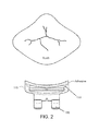
- FIG. 2 shows a top view of the present invention.
- FIG. 3 shows a facial view of the present invention.
- FIG. 4A shows a side view of an alternate embodiment of bracket of the present invention featuring the adhesive indention.
- FIG. 4B shows a side view of an alternate embodiment of bracket of the present invention featuring the adhesive indention.
- FIG. 4C shows a side view of an alternate embodiment of bracket of the present invention featuring the adhesive indention.
- FIG. 4D shows a side view of an alternate embodiment of bracket of the present invention featuring the adhesive indention.
- FIG. 4E shows a side view of an alternate embodiment of bracket of the present invention featuring the adhesive indention.
- FIG. 4F shows a side view of an alternate embodiment of bracket of the present invention featuring the adhesive indention.
- FIG. 4G shows a side view of an alternate embodiment of bracket of the present invention featuring the adhesive indention.
- FIG. 4H shows a side view of an alternate embodiment of bracket of the present invention featuring the adhesive indention.
- FIG. 5A-5I shows a lingual view of an alternate embodiment of bracket of the present invention featuring the adhesive indention.
- the present invention features an orthodontic bracket attachment system ( 100 ).
- the system ( 100 ) comprises a bracket base ( 110 ) having a bracket facial side ( 111 ), a bracket lingual side ( 112 ), a bracket top ( 113 ), a bracket bottom ( 114 ), a bracket mesial side ( 115 ), and a bracket distal side ( 116 ).
- the present invention features a wing ( 120 ) disposed on the bracket facial side ( 111 ).
- Orthodontic brackets ( 110 ) and wings ( 120 ) for wire attachment are well known to those of ordinary skill in the art.
- the system ( 100 ) comprises at least two separate and discrete adhesive indentions ( 130 ) disposed on the bracket lingual side ( 112 ).
- the adhesive indentions are definite undercut.
- the indentions may be of any appropriate shape, for example, linear slots, square, oval and/or circular. See for example, FIG. 5 .
- the first adhesive indention is located near a first side edge of the bracket base, and the second adhesive indention is located on the opposing second side edge of the bracket base, the first and second adhesive indention being elongated shape. See for example, FIG. 5D-5I .
- the adhesive indentions ( 130 ) comprise indention floors ( 131 ) offset from the bracket lingual side ( 112 ). As shown in FIG. 1 of the present invention, the bottom floors ( 131 ) of the adhesive indentions ( 130 ) are not directly interconnected to each other.
- the separate and discrete adhesive indentions ( 130 ) and detached indention floors ( 131 ) are beneficial for bracket attachment to the surface of the tooth since the peeling off of one adhesive indention can not affect the entire surface area of the lingual side ( 112 ) of the bracket base ( 110 ) when adhesive is applied to the bracket lingual side ( 112 ) flowing into adhesive indentions.
- the bottom floor of the first adhesive indention ( 201 ) has a first area unit (A 1 ) and the bottom floor of the second adhesive indention ( 202 ) has a second area unit (A 2 ).
- the ratio of the sum of first and second adhesive indention area units (A 1 +A 2 ) to the top surface area (A 3 ) of the lingual side ( 112 ) is less than 1:8.
- This low area ratio of bottom floors (A 1 +A 2 , etc.) to the top surface area A 3 is advantageous for bracket attachment to the surface of the tooth because the peeling off of one adhesive indention can not affect the anchoring surface of another adhesive indention as well as the anchoring surface of entire surface area of the lingual side ( 112 ) of the bracket base ( 110 ) when adhesive is applied to the bracket lingual side ( 112 ) flowing into adhesive indentions.
- the area ratio of the bottom floors of the adhesive indentions to the top surface area of the lingual side approaches 1:1, the whole anchoring surface of the grooves ( 207 ) which is adhered to the tooth surface bears a resemblance to a ‘grid’ as shown in FIG. 2 and FIG.
- the bracket base ( 110 ) is designed to be affixed to a surface of a tooth.
- adhesive is applied to the bracket lingual side ( 112 ) flowing into the adhesive indention ( 130 ).
- the bracket is affixed to the surface of the tooth via the adhesive. Adhesives used for bracket base ( 110 ) attachment are well known to those of ordinary skill in the art.
- a plurality of adhesive indentions ( 130 ) is located on the bracket lingual side ( 112 ). In some embodiments, two adhesive indentions ( 130 ) are located on the bracket lingual side ( 112 ). In some embodiments, three adhesive indentions ( 130 ) are located on the bracket lingual side ( 112 ). In some embodiments, four or more adhesive indentions ( 130 ) are located on the bracket lingual side ( 112 ).
- the adhesive indention ( 130 ) comprises an indention floor ( 131 ). In some embodiments, the adhesive indention ( 130 ) comprises an indention depth ( 132 ) from the bracket lingual side ( 112 ) to the indention floor ( 131 ).
- the indention floor ( 131 ) is flat. In some embodiments, the indention floor ( 131 ) is hemispherical. In some embodiments, the indention floor ( 131 ) tapers to a point.
- the adhesive indention ( 130 ) comprises tapered indention walls ( 134 ) from the bracket lingual side ( 112 ) to the indention floor ( 131 ). In some embodiments, an indention diameter ( 133 ) decreases from the bracket lingual side ( 112 ) to the indention floor ( 131 ). In some embodiments, the adhesive indention ( 130 ) comprises tapered indention walls ( 134 ) from the bracket lingual side ( 112 ) to the indention floor ( 131 ). In some embodiments, an indention diameter ( 133 ) increases from the bracket lingual side ( 112 ) to the indention floor ( 131 ).
- the adhesive indention ( 130 ) is a channel located from the bracket facial side ( 111 ) to the bracket lingual side ( 112 ). In some embodiments, the channel passes entirely through the bracket base ( 110 ).
- the adhesive indention ( 130 ) is located proximal to the bracket top ( 113 ). In some embodiments, the adhesive indention ( 130 ) is located proximal to the bracket bottom ( 114 ). In some embodiments, the adhesive indention ( 130 ) is located proximal to the bracket mesial side ( 115 ) or the bracket distal side ( 116 ).
- the adhesive indention ( 130 ) is round at the bracket lingual side ( 112 ). In some embodiments, the adhesive indention ( 130 ) is rectangular at the bracket lingual side ( 112 ). In some embodiments, the adhesive indentation is polygonal at the bracket lingual side ( 112 ). In some embodiments, the adhesive indentation is irregularly shaped at the bracket lingual side ( 112 ).
- the indention floor ( 131 ) comprises a pinhole channel ( 140 ) located between the indention floor ( 131 ) and the bracket facial side ( 111 ).
- the pinhole channel ( 140 ) is an air vent when adhesive is applied to the bracket lingual side ( 112 ) flowing into the adhesive indention ( 130 ).
- the term “about” refers to plus or minus 10% of the referenced number.
- descriptions of the inventions described herein using the phrase “comprising” includes embodiments that could be described as “consisting of”, and as such the written description requirement for claiming one or more embodiments of the present invention using the phrase “consisting of” is met.
Abstract
An orthodontic bracket attachment system featuring brackets for orthodontic braces. The system features a wing located on a bracket facial side. The system features an adhesive indention located on a bracket lingual side. The orthodontic bracket is designed to be affixed to a surface of a tooth. Adhesive is applied to the bracket lingual side flowing into the adhesive indention. The bracket is affixed to the surface of the tooth via the adhesive.
Description
This application claims priority to U.S. patent application Ser. No. 14/167,098, filed Jan. 29, 2014, the specification(s) of which is/are incorporated herein in their entirety by reference.
The present invention relates to brackets for orthodontic braces.
Orthodontic brackets are a component in an orthodontic brace system that cements to a tooth of a wearer. On occasion, however, the orthodontic bracket can pop off of the tooth, requiring a trip to the orthodontist for reattachment, thus a need exists for an improved orthodontic bracket attachment system. The present invention features an orthodontic bracket attachment system.
Any feature or combination of features described herein are included within the scope of the present invention provided that the features included in any such combination are not mutually inconsistent as will be apparent from the context, this specification, and the knowledge of one of ordinary skill in the art. Additional advantages and aspects of the present invention are apparent in the following detailed description and claims.
The present invention features an orthodontic bracket attachment system. In some embodiments, the system comprises an orthodontic bracket. In some embodiments, the system comprises a wing located on a bracket facial side. In some embodiments, the system comprises an adhesive indention located on a bracket lingual side.
In some embodiments, the orthodontic bracket is designed to be affixed to a surface of a tooth. In some embodiments, adhesive is applied to the bracket lingual side flowing into the adhesive indention. In some embodiments, the bracket is affixed to the surface of the tooth via the adhesive.
Following is a list of elements corresponding to a particular element referred to herein:
-
- 100 Orthodontic bracket attachment system
- 110 Bracket base
- 111 Bracket facial side
- 112 Bracket lingual side
- 113 Bracket top
- 114 Bracket bottom
- 115 Bracket mesial side
- 116 Bracket distal side
- 120 Wing
- 130 Adhesive indention
- 131 Indention floor
- 132 Indention depth
- 133 Indention diameter
- 134 Indention wall
- 140 Pinhole channel
Referring now to FIG. 1-5B , the present invention features an orthodontic bracket attachment system (100). In some embodiments, the system (100) comprises a bracket base (110) having a bracket facial side (111), a bracket lingual side (112), a bracket top (113), a bracket bottom (114), a bracket mesial side (115), and a bracket distal side (116).
Referring now to FIG. 1 , the present invention features a wing (120) disposed on the bracket facial side (111). Orthodontic brackets (110) and wings (120) for wire attachment are well known to those of ordinary skill in the art.
In some embodiments, the system (100) comprises at least two separate and discrete adhesive indentions (130) disposed on the bracket lingual side (112). The adhesive indentions are definite undercut. In some embodiments, the indentions may be of any appropriate shape, for example, linear slots, square, oval and/or circular. See for example, FIG. 5 .
In some embodiments, the first adhesive indention is located near a first side edge of the bracket base, and the second adhesive indention is located on the opposing second side edge of the bracket base, the first and second adhesive indention being elongated shape. See for example, FIG. 5D-5I .
In some embodiments, the adhesive indentions (130) comprise indention floors (131) offset from the bracket lingual side (112). As shown in FIG. 1 of the present invention, the bottom floors (131) of the adhesive indentions (130) are not directly interconnected to each other. The separate and discrete adhesive indentions (130) and detached indention floors (131) are beneficial for bracket attachment to the surface of the tooth since the peeling off of one adhesive indention can not affect the entire surface area of the lingual side (112) of the bracket base (110) when adhesive is applied to the bracket lingual side (112) flowing into adhesive indentions. This feature of having multiple discrete indentations where the respective bottom floors do not interconnect is uniquely different over Busch prior art (US 2008/0085486 A1). As shown in FIG. 4 in Busch patent application publication (US 2008/0085486 A1), the grooves (207) which are disposed on the top side, bottom side, mesial side and distal side of the etched bracket are interconnected with each other and spread all around the inner surface of the bracket lingual side. As a result, when adhesive is applied, the adhesive also fills in the entire grooves surface (207) of the tooth facing side of the bracket. The disadvantage of the interconnected groove floors of Busch patent application publication (US 2008/0085486 A1) is that the peeling off of partial anchoring surface area of the tooth facing side of the bracket will affect the entire surface area since adhesive is dispersed all over the entire interconnected groove surface of the bracket lingual side.
In some embodiments, the bottom floor of the first adhesive indention (201) has a first area unit (A1) and the bottom floor of the second adhesive indention (202) has a second area unit (A2). In some embodiments, the ratio of the sum of first and second adhesive indention area units (A1+A2) to the top surface area (A3) of the lingual side (112) is less than 1:8. This low area ratio of bottom floors (A1+A2, etc.) to the top surface area A3 is advantageous for bracket attachment to the surface of the tooth because the peeling off of one adhesive indention can not affect the anchoring surface of another adhesive indention as well as the anchoring surface of entire surface area of the lingual side (112) of the bracket base (110) when adhesive is applied to the bracket lingual side (112) flowing into adhesive indentions. In contrast, when the area ratio of the bottom floors of the adhesive indentions to the top surface area of the lingual side approaches 1:1, the whole anchoring surface of the grooves (207) which is adhered to the tooth surface bears a resemblance to a ‘grid’ as shown in FIG. 2 and FIG. 4 of Busch patent application publication (US 2008/0085486 A1). The particular disadvantage of this ‘grid’ like anchoring surface is that the adhesive is dispersed on entire interconnected grooves and peeling off of partial surface area will affect the entire surface area of the bracket lingual side.
In some embodiments, the bracket base (110) is designed to be affixed to a surface of a tooth. In some embodiments, adhesive is applied to the bracket lingual side (112) flowing into the adhesive indention (130). In some embodiments, the bracket is affixed to the surface of the tooth via the adhesive. Adhesives used for bracket base (110) attachment are well known to those of ordinary skill in the art.
In some embodiments, a plurality of adhesive indentions (130) is located on the bracket lingual side (112). In some embodiments, two adhesive indentions (130) are located on the bracket lingual side (112). In some embodiments, three adhesive indentions (130) are located on the bracket lingual side (112). In some embodiments, four or more adhesive indentions (130) are located on the bracket lingual side (112).
In some embodiments, the adhesive indention (130) comprises an indention floor (131). In some embodiments, the adhesive indention (130) comprises an indention depth (132) from the bracket lingual side (112) to the indention floor (131).
In some embodiments, the indention floor (131) is flat. In some embodiments, the indention floor (131) is hemispherical. In some embodiments, the indention floor (131) tapers to a point.
In some embodiments, the adhesive indention (130) comprises tapered indention walls (134) from the bracket lingual side (112) to the indention floor (131). In some embodiments, an indention diameter (133) decreases from the bracket lingual side (112) to the indention floor (131). In some embodiments, the adhesive indention (130) comprises tapered indention walls (134) from the bracket lingual side (112) to the indention floor (131). In some embodiments, an indention diameter (133) increases from the bracket lingual side (112) to the indention floor (131).
In some embodiments, the adhesive indention (130) is a channel located from the bracket facial side (111) to the bracket lingual side (112). In some embodiments, the channel passes entirely through the bracket base (110).
In some embodiments, the adhesive indention (130) is located proximal to the bracket top (113). In some embodiments, the adhesive indention (130) is located proximal to the bracket bottom (114). In some embodiments, the adhesive indention (130) is located proximal to the bracket mesial side (115) or the bracket distal side (116).
In some embodiments, the adhesive indention (130) is round at the bracket lingual side (112). In some embodiments, the adhesive indention (130) is rectangular at the bracket lingual side (112). In some embodiments, the adhesive indentation is polygonal at the bracket lingual side (112). In some embodiments, the adhesive indentation is irregularly shaped at the bracket lingual side (112).
In some embodiments, the indention floor (131) comprises a pinhole channel (140) located between the indention floor (131) and the bracket facial side (111). In some embodiments, the pinhole channel (140) is an air vent when adhesive is applied to the bracket lingual side (112) flowing into the adhesive indention (130).
As used herein, the term “about” refers to plus or minus 10% of the referenced number.
Various modifications of the invention, in addition to those described herein, will be apparent to those skilled in the art from the foregoing description. Such modifications are also intended to fall within the scope of the appended claims. Each reference cited in the present application is incorporated herein by reference in its entirety.
Although there has been shown and described the preferred embodiment of the present invention, it will be readily apparent to those skilled in the art that modifications may be made thereto which do not exceed the scope of the appended claims. Therefore, the scope of the invention is only to be limited by the following claims. Reference numbers recited in the claims are exemplary and for ease of review by the patent office only, and are not limiting in any way. In some embodiments, the figures presented in this patent application are drawn to scale, including the angles, ratios of dimensions, etc. In some embodiments, the figures are representative only and the claims are not limited by the dimensions of the figures. In some embodiments, descriptions of the inventions described herein using the phrase “comprising” includes embodiments that could be described as “consisting of”, and as such the written description requirement for claiming one or more embodiments of the present invention using the phrase “consisting of” is met.
The reference numbers recited in the below claims are solely for ease of examination of this patent application, and are exemplary, and are not intended in any way to limit the scope of the claims to the particular features having the corresponding reference numbers in the drawings.
Claims (17)
1. An orthodontic bracket attachment system (100), wherein the system (100) comprises:
(a) a bracket base (110) having a bracket facial side (111), a bracket lingual side (112), a bracket top (113), a bracket bottom (114), a bracket mesial side (115), and a bracket distal side (116);
(b) a wing (120) disposed on the bracket facial side (111); and
(c) at least two separate and discrete indentions (130) disposed on the bracket lingual side (112), wherein the indentations (130) are configured to receive adhesive;
wherein the indentions (130) comprise an indention floor (131) offset from the bracket lingual side (112), wherein a bottom floor (131) of a first indention (130) is not directly interconnected to the bottom floor of a second indention, wherein the bottom floor of the first indention (201) has a first area unit (A1) and the bottom floor of the second indention (202) has a second area unit (A2), wherein a ratio of the sum of first and second indention area units (A1+A2) to a top surface area (A3) of the lingual side (112) is less than 1:8,
wherein each indentation has an indentation diameter (133), wherein the indentations are spaced from each other such that a shortest distance between the indentations is at least equal to or greater than a maximum value of the indentation diameter (133) at the bracket lingual side (112).
2. The system (100) of claim 1 , wherein the indention (130) comprises an indention depth (132) from the bracket lingual side (112) to the indention floor (131), wherein the indention floor (131) comprises a pinhole channel (140) disposed between the indention floor (131) and the bracket facial side (111); wherein each indention (130) comprises a single indention floor (131) within said indention (130), and a single pinhole channel (140) within said indention floor (131);
wherein the bracket base (110) is designed to be affixed to a surface of a tooth, wherein adhesive is applied to the bracket lingual side (112) flowing into the discrete and separate indentions (130), wherein the pinhole channel (140) is an air vent such that adhesive applied to the bracket lingual side (112) flows into the discrete and separate indentions (130), allowing air to escape the indentions (130) through the pinhole channel (140), wherein the bracket is configured to affixed to the surface of the tooth via the adhesive.
3. The system (100) of claim 1 , wherein a plurality of indentions (130) is disposed on the bracket lingual side (112).
4. The system (100) of claim 1 , wherein the indention floor (131) is flat.
5. The system (100) of claim 1 , wherein the indention floor (131) is hemispherical.
6. The system (100) of claim 1 , wherein the indention floor (131) tapers to a point.
7. The system (100) of claim 1 , wherein the indention (130) comprises tapered indention walls (134) from the bracket lingual side (112) to the indention floor (131), wherein the indention diameter (133) decreases from the bracket lingual side (112) to the indention floor (131).
8. The system (100) of claim 1 , wherein the indention (130) comprises tapered indention walls (134) from the bracket lingual side (112) to the indention floor (131), wherein an indention diameter (133) increases from the bracket lingual side (112) to the indention floor (131).
9. The system (100) of claim 1 , wherein the indentions (130) are disposed proximal to the bracket top (113).
10. The system (100) of claim 1 , wherein the indentions (130) are disposed proximal to the bracket bottom (114).
11. The system (100) of claim 1 , wherein the indentions (130) are disposed proximal to the bracket mesial side (115) or the bracket distal side (116).
12. The system (100) of claim 1 , wherein the indentions (130) are round at the bracket lingual side (112).
13. The system (100) of claim 1 , wherein the indentions (130) are rectangular at the bracket lingual side (112).
14. The system (100) of claim 1 , wherein the indentations (130) are polygonal at the bracket lingual side (112).
15. An orthodontic bracket attachment system (100), wherein the system (100) comprises:
(a) a bracket base (110) having a bracket facial side (111), a bracket lingual side (112), a bracket top (113), a bracket bottom (114), a bracket mesial side (115), and a bracket distal side (116);
(b) a wing (120) disposed on the bracket facial side (111); and
(c) at least two separate and discrete indentions (130) disposed on the bracket lingual side (112), wherein the indentations (130) are configured to receive adhesive;
wherein the indentions (130) comprise an indention floor (131) offset from the bracket lingual side (112), wherein a bottom floor (131) of a first indention (130) is not directly interconnected to the bottom floor of a second indention, wherein the bottom floor of the first indention (201) has a first area unit (A1) and the bottom floor of the second indention (202) has a second area unit (A2), wherein a ratio of the sum of first and second indention area units (A1+A2) to a top surface area (A3) of the lingual side (112) is less than 1:8;
wherein the first indention is located near a first side edge of the bracket base, and the second indention is located on the opposing second side edge of the bracket base,
wherein the indentations are spaced from each other such that a shortest distance between the indentations is at least equal to or greater than a maximum value of an indentation diameter (133) of each indentation, said indentation diameter (133) being measured at the bracket lingual side (112).
16. An orthodontic bracket attachment system (100), wherein the system (100) comprises:
(a) a bracket base (110) having a bracket facial side (111), a bracket lingual side (112), a bracket top (113), a bracket bottom (114), a bracket mesial side (115), and a bracket distal side (116);
(b) a wing (120) disposed on the bracket facial side (111); and
(c) at least two separate and discrete indentions (130) disposed on the bracket lingual side (112), wherein the indentations (130) are configured to receive adhesive;
wherein the indentions (130) comprise an indention floor (131) offset from the bracket lingual side (112), wherein a bottom floor (131) of a first indention (130) is not directly interconnected to the bottom floor of a second indention, wherein the bottom floor of the first indention (201) has a first area unit (A1) and the bottom floor of the second indention (202) has a second area unit (A2), wherein a ratio of the sum of first and second indention area units (A1+A2) to a top surface area (A3) of the lingual side (112) is less than 1:8,
wherein the indention floor (131) comprises a pinhole channel (140) disposed between the indention floor (131) and the bracket facial side (111); wherein each indention (130) comprises a single indention floor (131) within said indention (130), and a single pinhole channel (140) within said indention floor (131);
wherein a diameter of the pinhole channel at the bracket facial side (111) is smaller than an indentation diameter (133) of the indentation (130) at the bracket lingual side (112);
wherein the bracket base (110) is designed to be affixed to a surface of a tooth, wherein adhesive is applied to the bracket lingual side (112) flowing into the discrete and separate indentions (130), wherein the pinhole channel (140) is an air vent such that adhesive applied to the bracket lingual side (112) flows into the discrete and separate indentions (130), allowing air to escape the indentions (130) through the pinhole channel (140), wherein the bracket is configured to affixed to the surface of the tooth via the adhesive.
17. The system (100) of claim 16 , wherein the indentations (130) are spaced from each other such that a shortest distance between the indentations is at least equal to or greater than a maximum value of the indentation diameter (133) at the bracket lingual side (112).
Priority Applications (1)
| Application Number | Priority Date | Filing Date | Title |
|---|---|---|---|
| US14/717,522 US9949805B1 (en) | 2014-01-29 | 2015-05-20 | Orthodontic brace bracket attachment system |
Applications Claiming Priority (2)
| Application Number | Priority Date | Filing Date | Title |
|---|---|---|---|
| US201414167098A | 2014-01-29 | 2014-01-29 | |
| US14/717,522 US9949805B1 (en) | 2014-01-29 | 2015-05-20 | Orthodontic brace bracket attachment system |
Related Parent Applications (1)
| Application Number | Title | Priority Date | Filing Date |
|---|---|---|---|
| US201414167098A Continuation-In-Part | 2014-01-29 | 2014-01-29 |
Publications (1)
| Publication Number | Publication Date |
|---|---|
| US9949805B1 true US9949805B1 (en) | 2018-04-24 |
Family
ID=61952350
Family Applications (1)
| Application Number | Title | Priority Date | Filing Date |
|---|---|---|---|
| US14/717,522 Active 2034-11-10 US9949805B1 (en) | 2014-01-29 | 2015-05-20 | Orthodontic brace bracket attachment system |
Country Status (1)
| Country | Link |
|---|---|
| US (1) | US9949805B1 (en) |
Cited By (1)
| Publication number | Priority date | Publication date | Assignee | Title |
|---|---|---|---|---|
| EP3644892A4 (en) * | 2017-06-26 | 2021-03-10 | Murrell, Fred | Retentive orthodontic dental appliances and methods of making same |
Citations (10)
| Publication number | Priority date | Publication date | Assignee | Title |
|---|---|---|---|---|
| US3932940A (en) * | 1971-12-06 | 1976-01-20 | Andren Frank J | Dental appliance |
| US4094068A (en) | 1975-08-01 | 1978-06-13 | Scheu-Dental Inh. Rudolf Scheu Herstellung & Vertrieb Von Dentalbedarf | Orthodontic bracket assembly |
| US4604057A (en) | 1985-07-03 | 1986-08-05 | American Orthodontics Corporation | Cast orthodontic appliance |
| US4759714A (en) * | 1980-06-26 | 1988-07-26 | Georg Szegvary | Tooth root channel anchor |
| US4842513A (en) | 1985-11-23 | 1989-06-27 | Harodent-Kfo Dental-Vertrieb Gmbh | Orthodontic device |
| US4936773A (en) * | 1989-02-02 | 1990-06-26 | Gac International, Inc. | Orthodontic apparatus having an improved base portion |
| US5902104A (en) | 1996-12-04 | 1999-05-11 | Yamada; Kenjiro | Orthodontic wire supporting device |
| US20080085486A1 (en) | 2006-10-04 | 2008-04-10 | Injectamax Corporation | Malleable Orthodontic Bracket |
| US20110047799A1 (en) | 2005-01-25 | 2011-03-03 | Ormco Corporation | Laser shaped green metal body and orthodontic bracket |
| US20110281228A1 (en) * | 2009-05-20 | 2011-11-17 | Pbd, Patent & Business Development Ag | Polycrystalline ceramic orthodontic component |
-
2015
- 2015-05-20 US US14/717,522 patent/US9949805B1/en active Active
Patent Citations (10)
| Publication number | Priority date | Publication date | Assignee | Title |
|---|---|---|---|---|
| US3932940A (en) * | 1971-12-06 | 1976-01-20 | Andren Frank J | Dental appliance |
| US4094068A (en) | 1975-08-01 | 1978-06-13 | Scheu-Dental Inh. Rudolf Scheu Herstellung & Vertrieb Von Dentalbedarf | Orthodontic bracket assembly |
| US4759714A (en) * | 1980-06-26 | 1988-07-26 | Georg Szegvary | Tooth root channel anchor |
| US4604057A (en) | 1985-07-03 | 1986-08-05 | American Orthodontics Corporation | Cast orthodontic appliance |
| US4842513A (en) | 1985-11-23 | 1989-06-27 | Harodent-Kfo Dental-Vertrieb Gmbh | Orthodontic device |
| US4936773A (en) * | 1989-02-02 | 1990-06-26 | Gac International, Inc. | Orthodontic apparatus having an improved base portion |
| US5902104A (en) | 1996-12-04 | 1999-05-11 | Yamada; Kenjiro | Orthodontic wire supporting device |
| US20110047799A1 (en) | 2005-01-25 | 2011-03-03 | Ormco Corporation | Laser shaped green metal body and orthodontic bracket |
| US20080085486A1 (en) | 2006-10-04 | 2008-04-10 | Injectamax Corporation | Malleable Orthodontic Bracket |
| US20110281228A1 (en) * | 2009-05-20 | 2011-11-17 | Pbd, Patent & Business Development Ag | Polycrystalline ceramic orthodontic component |
Cited By (1)
| Publication number | Priority date | Publication date | Assignee | Title |
|---|---|---|---|---|
| EP3644892A4 (en) * | 2017-06-26 | 2021-03-10 | Murrell, Fred | Retentive orthodontic dental appliances and methods of making same |
Similar Documents
| Publication | Publication Date | Title |
|---|---|---|
| US8550814B1 (en) | Multi-component orthodontic bracket assembly | |
| EP2764859A3 (en) | Dental resin modified glass-ionomer composition | |
| BR112018003271B1 (en) | Nasogastric tube fixation system, kit and method of fixation of a nasogastric tube | |
| US9949805B1 (en) | Orthodontic brace bracket attachment system | |
| EP3158968B1 (en) | Bracket, bracket straightening system and teeth straightening method | |
| US20160000530A1 (en) | Base Configuration for Orthodontic Bracket | |
| JP2018512205A5 (en) | ||
| WO2018148321A8 (en) | Maxillomandibular fixation devices | |
| EP4306083A3 (en) | Cerebral blood flow reorganization | |
| ES2542682T3 (en) | A device for correcting ingrown toenails | |
| US9277818B1 (en) | Corner shelf system | |
| WO2016115122A1 (en) | Orthodontic bracket | |
| WO2012027396A1 (en) | Dental wedge device with guiding wire | |
| WO2016171593A1 (en) | Retractor for protecting the tongue and cheek during dental treatment | |
| EP2944286A3 (en) | Osteotome for dental medicine with variable angulation of the active tip | |
| y Convencionales | Evaluation in vitro of frictional resistance of self-ligating esthetic and conventional brackets | |
| Krishnan et al. | An adjunctive minor surgical procedure for increased rate of retraction | |
| US9538780B1 (en) | Chewing tobacco protective barrier system | |
| CN212089802U (en) | Shell-like dental instrument | |
| Amaral et al. | Evaluación In Vitro de la Resistencia Friccional en Brackets de Autoligado Estéticos y Convencionales | |
| JP2005185428A (en) | Bracket for orthodontics | |
| KADOTANI et al. | Activities for Improved Hand Hygiene of Clinical Laboratory Technicians | |
| US20120070795A1 (en) | Orthodontic Appliance | |
| Tomoo et al. | Cone-beam computed tomography evaluation of the association of cortical plate proximity and apical root resorption after orthodontic treatment | |
| Paulo et al. | Retention Probability Of Permanent Mandibular Second Molars (Pilot study) |
Legal Events
| Date | Code | Title | Description |
|---|---|---|---|
| STCF | Information on status: patent grant |
Free format text: PATENTED CASE |
|
| MAFP | Maintenance fee payment |
Free format text: PAYMENT OF MAINTENANCE FEE, 4TH YR, SMALL ENTITY (ORIGINAL EVENT CODE: M2551); ENTITY STATUS OF PATENT OWNER: SMALL ENTITY Year of fee payment: 4 |