US994635A - Car-truck. - Google Patents
Car-truck. Download PDFInfo
- Publication number
- US994635A US994635A US60188311A US1911601883A US994635A US 994635 A US994635 A US 994635A US 60188311 A US60188311 A US 60188311A US 1911601883 A US1911601883 A US 1911601883A US 994635 A US994635 A US 994635A
- Authority
- US
- United States
- Prior art keywords
- truck
- bolster
- side frames
- journal
- frames
- Prior art date
- Legal status (The legal status is an assumption and is not a legal conclusion. Google has not performed a legal analysis and makes no representation as to the accuracy of the status listed.)
- Expired - Lifetime
Links
- 238000010276 construction Methods 0.000 description 12
- 230000004048 modification Effects 0.000 description 2
- 238000012986 modification Methods 0.000 description 2
- 230000000717 retained effect Effects 0.000 description 1
Images


Classifications
-
- B—PERFORMING OPERATIONS; TRANSPORTING
- B61—RAILWAYS
- B61F—RAIL VEHICLE SUSPENSIONS, e.g. UNDERFRAMES, BOGIES OR ARRANGEMENTS OF WHEEL AXLES; RAIL VEHICLES FOR USE ON TRACKS OF DIFFERENT WIDTH; PREVENTING DERAILING OF RAIL VEHICLES; WHEEL GUARDS, OBSTRUCTION REMOVERS OR THE LIKE FOR RAIL VEHICLES
- B61F3/00—Types of bogies
- B61F3/02—Types of bogies with more than one axle
- B61F3/08—Types of bogies with more than one axle without driven axles or wheels
Definitions
- Fig. 2 ir. a view, ⁇ partly in HARRY C. BUHOUP, OF CHICAGO. ILLINOIS.
- My invention relates tothe construction of trucks for railway vehicles. and hare ⁇ for vits principal object the production ol a truck in ,which the parts are yielrlingly connected, wl'xcreby the. flange wear of the truck wheels ie greatly reduced. l
- the principal feature of my invention consists in .ago combining the side frames of a car truck with the bolster that. the latter may have a pivotal further feature of my invention consista 1n .so combining the journal boxes with the have horizontal movement with respect to Ithe side frames.
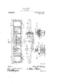
- Figure l is a View partly in 51de elevation and partly 1n vertical Section, ofa ear truck embodying plan and partly in horizontal section, 'ot' one.
- Side olf' the car truck shown in Fig. l
- Fig. is a View taken in the plane ot the line 15MB, Fig. l, the journal. box being shown in elevation
- Fig. 4- is a sectional view taken in the plane ol. ⁇ the line #lf-Il, liig.y l
- Fig. 5 is a side elevation of a modified torni of car truck embodying luy-invention; Fig.
- t is a View, partly in plan and partly in horizontal Section, of one side v.of the car truck illustrated in ⁇ Fig. 5;
- Fig. 7 is a vertical central l section taken in the. plane of the line 7"-7 F igft, the bolsterlbeing .shown in elevation;
- Fig. 8 i5' a vertical section taken in the plane of the line 8-8, Fig. 5;
- Fig. 9 ia a Side elevation ofone-halfof a'car truck embodying -a modified form -ot' connection between the side frames and journal boxes;
- Fig. 10 is a detail view showing in side elevation one end -of the side, frame illustrated in Fig. 9;
- Fig. 10 is a detail view showing in side elevation one end -of the side, frame illustrated in Fig. 9;
- Fig. 10 is a detail view showing in side elevation one end -of the side, frame illustrated in Fig. 9;
- Fig. 10 is a detail
- Fig. Fig. 12 is a side elevation of one-halt' ot a truck frame emliodyinga further modified 'form of means for movably connecting the journal boxes to the side frames
- Fig. 13 is a detail side elevation of one end of a truck embodying my invention showing a further moditied means ot' connecting the journal boxes to the side frame
- Fig. 14 is a vertical Section taken in the plane of the line lll-14, Fig. 13.
- the bolster 2 is preferably supported by the springs Ll, l through the intermediaey of a Spring seat 5 which rests upon-the upper ends of the bolster springs and is provided on its upper aurlare with a concave spherical Socket into which a correspondingly curved convex projection (i formed ⁇ on the under Side ot' the bolster lits.
- "lhe seats 5 may be conveniently guided in their movements by means el guide lrib; 7 formed integral with the side trames and extending upwardly a sullicient distance troni the bases of the boliater openinga il'ornied therein.
- tieeuretl'to the end of the bolster 2, as by means o ll holte S, and extending' parallel with the side 'traine l is a bar t) which is yield ingly connected te the side traine on oppoeite Hidesy of the bolster opening.
- This yielding connection oi the bar il with the adjacent side'frame i is pre'terably Sucl as will permit the Said bar and beleter to have y not only a vertical movement with respect to the side traine but also a.
- each side trame ith vertically,extending aperturea thatare located on oppoSite sides of the bolster oj'iening and to form the ends of each o1" the bars 9 with parallel guide members 10 which extend inwardly into said apertures and receive between theml followers 11 and 12 between which horizontally extending springs 13 are interposed.
- the horizontally' arranged springs 13 may be retained in position ⁇ between' their respective followers by means of bolts 14 which also-serve to prevent the followers 11 and 12 from becoming disassociated from the side frames.
- the ol lowers 11 vand 12 are capable of movement upper end of eachv of these springs is sur.
- a spring seat 16 that engages the under faces of the lower guide member 10, Ythe engagement being such as will permit the said guide member to slide ⁇ upon said spring seat' in the direction or" length of the bolster.
- The'journal -boxes 3 are 'preferably' connected to the side frames 1 by means of detachable ournal box yokes 17 which may be secured to the side frames by means of keys 18.
- the journal boxes are preferably so mounted in the side frame as to be capable of moving horizontally with respect to said'side frames in the direction of length of the truck axles and Valso to be capable of a limited pivotal motion with respect to the side frames about a vertical axis.
- each end of the side frame and also each of the journal box yokes 17 is preferably formed with a box 19within and upon which is .seated horizontally arranged springs 20' that bear upon the opposite sides of a slidable pintle socket 21 into which a pintle 22 vformed upon the adjacent side of the ournal box 3 extends.
- Figs. 5 to 8 inclusive a eon struction in which the side frames are designed to have only a horizontal rotation with respect to the bolster., instead of being permitted to rotate both/horizontally and vertically with respect thereto, as in the form of construction illustrated in Figs. 1 to 4 inclusive.
- the curved bearing member 6 with which each' end of the bolster 2 is provided is omitted, an d the bolster is formed with ilat lower faces which rest. directly upon the upper ends of bolstersupporting springs 24 that are seated upon a spring plank 25 which g is provided at eacend with members 26 having cylindrical hubs 27 that are journaled in the corresponding recesses in the side frames 28.
- the cylindrical hubs. 27 may be made stifliciently large to alone form the pivotal connection between the bolditionally employ for this purpose vertically extending bolts 29 which pass through the ends of the bolster 23 and the upper and lower rails of each of the side frames 28.
- each of the bars 9 is provided with guide members 10, 10 which enter vertically extending recesses in the side trame on op# posite sides of the bolster opening therein.
- journal-boxes 3 which are illustrated in this form of construction are arranged to be capable of a horizontal movement' with respect to the side frames, the said journal boxes being for this purpose provided with vertically extending pintles 22, the upper one of which on each journal box enters a corresponding cylindrical socket 30 formed in the end of the side frame and the lower.
- each -journal box 32 vis provided with a plurality of rigidly attached 'followers 34 that are adapted to compress a horiwhich is normally seated upon spring seats seats seats being slotted as at 37 to permit the fol# lowers 34: to move inwardly and ⁇ outwardly nected to the side frames 33 by means of journal box yokes.
- Figs. 9 to 11 inclusive illustrate a furL 36 formed on the side frame, said spring V11,5 in a .horizontal direction to thus compress the spring 35, as will be readily-understood.
- the journal boxes 3,2 may, ifdesired, be con;
- Fig. 12 of the drawings embodies the form 'of connection between the bolster and side frames shown in' j the principal igures of thek drawings, while H and sideb frames isjidentically the ⁇ same Vas that illustrated in Figs 5, 6,'7 and 8.
- each journal box is pretera bly yieldingly connected to its side frame by devices corresponding to those shown in 9.
- journal box being provided with a plurality of followers 4,3 corresponding in form and function to the followers 34 and vthe journal 'box yoke being provided with slotted spring seats 4st between which is interposed a spring fl-5 that is compressed when the journal box moves horizontally in either directionwith respect to the side frame.
- the wheels and axles of the truck are thus permitted to re,- tain vtheir normal positions to each other uninluenced by the angles which the side frames assume when the truck is passing around the curve, the wheels beingthus enabled .to travel on a curved track"with practically as little contact between their lflanges and the railsas occurs when the truck is moving on straight track. lVhen the truck leaves the curve the springs 13 force the side-"frames to their' normal positions.
- journal box yokes of journal boxes secured tov said side frames by said yokes, each of said journal boxes having a pivotal connection with ⁇ -its yoke and sideframe.
Landscapes
- Engineering & Computer Science (AREA)
- Mechanical Engineering (AREA)
- Body Structure For Vehicles (AREA)
Description
H. C. BUHUUP.
CAR TRUCK.
APPLICATION FILED JAN.10. 1911.
Patentel June 6, 1911.
H. C. BUHOUP.
GAR TRUCK.
APPLICATION FILED JAN.10. 1911.
Patented June 6, 1911.
3 SHEETS-SHEET 2.
H. C. BUHOUP.
CAR TRUCK.
APPLICATION FILED 11111.10. 1911.
94,635, Patented June 6,1911.
3 sHBB'Ts-SHBET s.
cago, in the county of Cool: and State of jllhnois, have invented certain new and use- `hcrebydeclare the following` to he a it'ull,
or rotar-y movement horizontally with re- Spet to the side frames.
-side frameS that the former are adapted to .my invention; Fig. 2 ir. a view,`partly in HARRY C. BUHOUP, OF CHICAGO. ILLINOIS.
CAR-TRUCK.
'Specification of Letters Patent.
Application filed January 10,
Patented June ti, Elli.. 1911. serial No. 601,883.
To all whom it may concern:
Be it known that I, HARRY C. BUHoUP, a citizen of the. United Statee'. residing at Chiful ln'iproveinents in Car-Trucha and I do clear, and exact description ot' the invention, such as will enable others skilled in the art to which it appertains to make and use the same. y
My invention relates tothe construction of trucks for railway vehicles. and hare` for vits principal object the production ol a truck in ,which the parts are yielrlingly connected, wl'xcreby the. flange wear of the truck wheels ie greatly reduced. l
The principal feature of my invention, generally stated, consists in .ago combining the side frames of a car truck with the bolster that. the latter may have a pivotal further feature of my invention consista 1n .so combining the journal boxes with the have horizontal movement with respect to Ithe side frames.
There are other features of invention residing in particular combinations and e|emental constrtwtions, all as will hereinafter more fully appear.
In the drawings chosen l'or thc purpose ol.
is pointed-out in the rianne, Figure l is a View partly in 51de elevation and partly 1n vertical Section, ofa ear truck embodying plan and partly in horizontal section, 'ot' one. Side olf' the car truck shown in Fig. l; Fig. is a View taken in the plane ot the line 15MB, Fig. l, the journal. box being shown in elevation; Fig. 4- is a sectional view taken in the plane ol.` the line #lf-Il, liig.y l; Fig. 5 is a side elevation of a modified torni of car truck embodying luy-invention; Fig. t is a View, partly in plan and partly in horizontal Section, of one side v.of the car truck illustrated in `Fig. 5; Fig. 7 is a vertical central l section taken in the. plane of the line 7"-7 F igft, the bolsterlbeing .shown in elevation; Fig. 8 i5' a vertical section taken in the plane of the line 8-8, Fig. 5; Fig. 9 ia a Side elevation ofone-halfof a'car truck embodying -a modified form -ot' connection between the side frames and journal boxes; Fig. 10 is a detail view showing in side elevation one end -of the side, frame illustrated in Fig. 9; Fig. ll-is a detail section taken in the plane of the line 11h11, Fig. Fig. 12 is a side elevation of one-halt' ot a truck frame emliodyinga further modified 'form of means for movably connecting the journal boxes to the side frames; Fig. 13 is a detail side elevation of one end of a truck embodying my invention showing a further moditied means ot' connecting the journal boxes to the side frame, and Fig. 14 is a vertical Section taken in the plane of the line lll-14, Fig. 13.
Like Symbols refer to like parts Whereever they occur.
l'will new proceed to describe my invention more fully, so thatothers skilled in the art to which it appertains may apply the saine. As both Sides ot each of the several tornl of trucks illustratedare designed to he ident ical in construction, only one Side of each torni ot truck will be described.
ln the dra\\'ing z, l is the truck Side frame, the bolster, and 3 the journal boxes. The side trames are provided with centrally located bolster openings which receive the usual bolster supporting Sl'nings 4, 4 As shown more particularly in Fig. l the bolster 2 is preferably supported by the springs Ll, l through the intermediaey of a Spring seat 5 which rests upon-the upper ends of the bolster springs and is provided on its upper aurlare with a concave spherical Socket into which a correspondingly curved convex projection (i formed` on the under Side ot' the bolster lits. "lhe seats 5 may be conveniently guided in their movements by means el guide lrib; 7 formed integral with the side trames and extending upwardly a sullicient distance troni the bases of the boliater openinga il'ornied therein.
tieeuretl'to the end of the bolster 2, as by means o ll holte S, and extending' parallel with the side 'traine l is a bar t) which is yield ingly connected te the side traine on oppoeite Hidesy of the bolster opening. This yielding connection oi the bar il with the adjacent side'frame i is pre'terably Sucl as will permit the Said bar and beleter to have y not only a vertical movement with respect to the side traine but also a. horizontal movement with respect thereto, For this purpose it is'prcterred to form each side trame ith vertically,extending aperturea thatare located on oppoSite sides of the bolster oj'iening and to form the ends of each o1" the bars 9 with parallel guide members 10 which extend inwardly into said apertures and receive between theml followers 11 and 12 between which horizontally extending springs 13 are interposed.
As shown in Figs. 2 and 4 the horizontally' arranged springs 13 may be retained in position `between' their respective followers by means of bolts 14 which also-serve to prevent the followers 11 and 12 from becoming disassociated from the side frames. The ol lowers 11 vand 12 are capable of movement upper end of eachv of these springs is sur.
mounted by a spring seat 16 that engages the under faces of the lower guide member 10, Ythe engagement being such as will permit the said guide member to slide `upon said spring seat' in the direction or" length of the bolster.
The'journal -boxes 3 are 'preferably' connected to the side frames 1 by means of detachable ournal box yokes 17 which may be secured to the side frames by means of keys 18. To secure a very high degree of ilexibility of thetruck, which will enable it to readily pass around curves, the journal boxes are preferably so mounted in the side frame as to be capable of moving horizontally with respect to said'side frames in the direction of length of the truck axles and Valso to be capable of a limited pivotal motion with respect to the side frames about a vertical axis. For this purpose each end of the side frame and also each of the journal box yokes 17 is preferably formed with a box 19within and upon which is .seated horizontally arranged springs 20' that bear upon the opposite sides of a slidable pintle socket 21 into which a pintle 22 vformed upon the adjacent side of the ournal box 3 extends.
In Figs. 5 to 8 inclusive, is shown a eon struction in which the side frames are designed to have only a horizontal rotation with respect to the bolster., instead of being permitted to rotate both/horizontally and vertically with respect thereto, as in the form of construction illustrated in Figs. 1 to 4 inclusive. In this modified form of construction the curved bearing member 6 with which each' end of the bolster 2 is provided is omitted, an d the bolster is formed with ilat lower faces which rest. directly upon the upper ends of bolstersupporting springs 24 that are seated upon a spring plank 25 which g is provided at eacend with members 26 having cylindrical hubs 27 that are journaled in the corresponding recesses in the side frames 28. lVhile the cylindrical hubs. 27 may be made stifliciently large to alone form the pivotal connection between the bolditionally employ for this purpose vertically extending bolts 29 which pass through the ends of the bolster 23 and the upper and lower rails of each of the side frames 28.
of the bolster 23 by 'means or bolts 3 shown as of identicallyv the same form as the parts indicated by corresponding letters ot' reference and heretoforeV described. Each end of each of the bars 9 is provided with guide members 10, 10 which enter vertically extending recesses in the side trame on op# posite sides of the bolster opening therein.
14, which areassociated with. .each end of operated in'identically the same manner as the correspondingly numberedv parts heretofore described with reference to Figs. l to l inclusive, of the drawings. i
The journal-boxes 3 which are illustrated in this form of construction are arranged to be capable of a horizontal movement' with respect to the side frames, the said journal boxes being for this purpose provided with vertically extending pintles 22, the upper one of which on each journal box enters a corresponding cylindrical socket 30 formed in the end of the side frame and the lower.
portion of the journal box yoke 31.
ther modification in which thev journal boxes and side frames may move horizontally with respect to each other. In this form of construction each -journal box 32 vis provided with a plurality of rigidly attached 'followers 34 that are adapted to compress a horiwhich is normally seated upon spring seats seats being slotted as at 37 to permit the fol# lowers 34: to move inwardly and `outwardly nected to the side frames 33 by means of journal box yokes.
the form or' connectionof the journal boxes several structural eatures'of this form `of truck are indicated by letters ot' reference The bars 9 which are secured to each end.
of which .enters a socket formed in the lower Y zontally extending journal box spring35I showing theiicorrespondence with. thelike ster and side rames,it is preferred to ad- Y The followers 11 and 12, springs 13 and bolts each bar 9, are constructed, arranged, and
Figs. 9 to 11 inclusive, illustrate a furL 36 formed on the side frame, said spring V11,5 in a .horizontal direction to thus compress the spring 35, as will be readily-understood. l The journal boxes 3,2may, ifdesired, be con;
The modification shown in Fig. 12 of the drawings embodies the form 'of connection between the bolster and side frames shown in' j the principal igures of thek drawings, while H and sideb frames isjidentically the `same Vas that illustrated in Figs 5, 6,'7 and 8. Thel Cil zontally with respect to the truck side frame.
t0. is provided' on each side-with wheels or rollers 41 upon which the side frame 40 rests. These rollers, which serve to reduce the friction between the side frames and journal boxes when these parts move horizontally with respect to each other, are journaled on oppositely arranged horizontal pintles 4Q which project outwardly from the sides of the journal box. When large rollers such as are shown in these figures of the drawings are employed each journal box is pretera bly yieldingly connected to its side frame by devices corresponding to those shown in 9. 10 and 11 ot the drawings, the journal box being provided with a plurality of followers 4,3 corresponding in form and function to the followers 34 and vthe journal 'box yoke being provided with slotted spring seats 4st between which is interposed a spring fl-5 that is compressed when the journal box moves horizontally in either directionwith respect to the side frame.
TWhen a truck such as shown in Figs. 1 to inclusive of the drawings passesl around a curve in the track, the front or leading end of one of the side frames rotates inwardly, thus compressing its spring 13 and forcing outwardly the leading end of the side frame on the opposite side of the truck, the rear end of each side frame moving in the reverse direction. As the journalboxes are pivotally and horizontally movable with respectto the side trames, the wheels and axles of the truck are thus permitted to re,- tain vtheir normal positions to each other uninluenced by the angles which the side frames assume when the truck is passing around the curve, the wheels beingthus enabled .to travel on a curved track"with practically as little contact between their lflanges and the railsas occurs when the truck is moving on straight track. lVhen the truck leaves the curve the springs 13 force the side-"frames to their' normal positions. It will be observed that in this construction the spherical bearings between the bolster' 2 and the .spring seats 5 permit the side frames to rotate vertically as well as horizontally, such a construction overcoming the possibility of deraihnent' which is often occasioned when 'a truck passes around a curve which is elevated on one side, or passes over high or Ilow joints. The springs 15 which permitV theA side lframes to yieldingly.
rotate with respect to the bolster, serve to maintain the normalrelation of the ksideframes and bolster. l
The operatmn of the form ol 'construction et construction heretofore deshown in Figs. 5 to 8 inclusive is substantially` the same as that heretofore described, except that the side frames are not designed to rotate vertically with respect to the bolster.
In thel constructions shown in Figs. 9, 10, 11, 13 and 14, when t'he front wheels uit' the truck strike a curve theside frames and Wheels axles and journal boxes move horizontally with respect to each other, but in these constructions, instead of the si cle-frames rotating the journal boxes travel or move through the side-frames, inwardly through 'one` side-frame and outwardly through the other, thereby reducing the friction of the wheel flanges unon the rails. This horizontal movement oI the journal boxes with respect to the side-trames causes the followers 34 or 42, as thecase may be. to compress the springs between them, so that when the truck passes on to straight track such springs expand and return the journal boxes to their normal positions.
Having thus described my inventiomwhat I claim and desire tosecure. by Letters Patent is:
1. In a car truck, the combination with side frames, of journal boxes pivotally mounted on said side frames and movable horizontally with respect to said side frames.
2. In a .car truck, the combination with side frames having detachable. journal box yokes, of journal boxes secured tov said side frames by said yokes, each of said journal boxes having a pivotal connection with `-its yoke and sideframe.
3. In a car truck, the combination with side frames having detachable yokes for securing journal boxes thereto, ot journal boxes movable horizontally with respect to said side-frames and yokes, and yielding` means interposed between cach journal box and its yoke for periiiittirig-s-:aid journal' boxes to move' horizontally with respect to said yokes and side-frames.'
4. In a car truck, the combination with side frames, of a bolster' pivotally connected to rotate horizontally with respect to said side frames.
5. In a car truck, the combination with side frames, of a bolster pivotally connected to said side frames so as to rotate horizontally with respect thereto, and springs interposed between said '-bolster and side frames and adapted. to be compressed by the rotation otsaid side frames with respect to said. bolster.
6. In a car truck, the combination with side frames, of a bolster pivotally connected thereto, and horizontally arranged springs interposed between said bolster' and sideframes. j p
7. In a cai;` truck, the combination with side-frames, f a bolster pivotally connected thereto, sprjiigs compressible by the horito be compvessed by :1 veteal roton ofi' the side-frame, and horizontallyextenling" springs interposed between each vskemmef .rand the bolster and adepte to be compressed by a horiz-@nml r ture, in the'vpreseneeof'rtwo snb'sobng yWil.-
nesses. l
HARRY ,CBUHOUP W'tnesses: 'A y D.B.MAsoN 4 HARRY W'. STA'NNnp.
Priority Applications (1)
| Application Number | Priority Date | Filing Date | Title |
|---|---|---|---|
| US60188311A US994635A (en) | 1911-01-10 | 1911-01-10 | Car-truck. |
Applications Claiming Priority (1)
| Application Number | Priority Date | Filing Date | Title |
|---|---|---|---|
| US60188311A US994635A (en) | 1911-01-10 | 1911-01-10 | Car-truck. |
Publications (1)
| Publication Number | Publication Date |
|---|---|
| US994635A true US994635A (en) | 1911-06-06 |
Family
ID=3062968
Family Applications (1)
| Application Number | Title | Priority Date | Filing Date |
|---|---|---|---|
| US60188311A Expired - Lifetime US994635A (en) | 1911-01-10 | 1911-01-10 | Car-truck. |
Country Status (1)
| Country | Link |
|---|---|
| US (1) | US994635A (en) |
Cited By (2)
| Publication number | Priority date | Publication date | Assignee | Title |
|---|---|---|---|---|
| US2551064A (en) * | 1945-03-29 | 1951-05-01 | Scullin Steel Co | Snubbed bolster truck |
| US20090123418A1 (en) * | 2007-11-08 | 2009-05-14 | Ambit Biosciences Corporation | Methods of administering n-(5-tert-butyl-isoxazol-3-yl)-n'-urea to treat proliferative disease |
-
1911
- 1911-01-10 US US60188311A patent/US994635A/en not_active Expired - Lifetime
Cited By (2)
| Publication number | Priority date | Publication date | Assignee | Title |
|---|---|---|---|---|
| US2551064A (en) * | 1945-03-29 | 1951-05-01 | Scullin Steel Co | Snubbed bolster truck |
| US20090123418A1 (en) * | 2007-11-08 | 2009-05-14 | Ambit Biosciences Corporation | Methods of administering n-(5-tert-butyl-isoxazol-3-yl)-n'-urea to treat proliferative disease |
Similar Documents
| Publication | Publication Date | Title |
|---|---|---|
| US1414960A (en) | Car truck | |
| US696617A (en) | Car-truck. | |
| US994635A (en) | Car-truck. | |
| US1138357A (en) | Car-truck. | |
| US555857A (en) | Island | |
| US1029582A (en) | Car-truck. | |
| US1147430A (en) | Car-truck. | |
| US821279A (en) | Car-truck. | |
| US755460A (en) | Electric locomotive. | |
| US800035A (en) | Car-truck. | |
| US1245323A (en) | Railway-car construction | |
| US1358043A (en) | Car-truck | |
| US993755A (en) | Truck for railway-cars. | |
| US798776A (en) | Car-truck. | |
| US736318A (en) | Four-wheel swing-fulcrum truck. | |
| US86685A (en) | Improved running-gear for railroad-cars | |
| US995560A (en) | Car construction. | |
| US225913A (en) | Railway-car | |
| US562607A (en) | Electric-locomotive truck | |
| US760292A (en) | Maximum-traction truck. | |
| US784096A (en) | Lateral-motion device for car-trucks. | |
| US1881139A (en) | Sprung bogie for railway and tramway cars | |
| US971929A (en) | Car-truck. | |
| US823482A (en) | Locomotive-truck. | |
| US576255A (en) | Center bearing for car-trucks |