US9946286B2 - Information processing apparatus, power-consuming body, information processing method, and program - Google Patents
Information processing apparatus, power-consuming body, information processing method, and program Download PDFInfo
- Publication number
- US9946286B2 US9946286B2 US14/429,494 US201314429494A US9946286B2 US 9946286 B2 US9946286 B2 US 9946286B2 US 201314429494 A US201314429494 A US 201314429494A US 9946286 B2 US9946286 B2 US 9946286B2
- Authority
- US
- United States
- Prior art keywords
- power
- time point
- transition
- demand
- function
- Prior art date
- Legal status (The legal status is an assumption and is not a legal conclusion. Google has not performed a legal analysis and makes no representation as to the accuracy of the status listed.)
- Expired - Fee Related, expires
Links
Images




Classifications
-
- G—PHYSICS
- G05—CONTROLLING; REGULATING
- G05F—SYSTEMS FOR REGULATING ELECTRIC OR MAGNETIC VARIABLES
- G05F1/00—Automatic systems in which deviations of an electric quantity from one or more predetermined values are detected at the output of the system and fed back to a device within the system to restore the detected quantity to its predetermined value or values, i.e. retroactive systems
- G05F1/66—Regulating electric power
-
- B60L11/1824—
-
- B60L11/1844—
-
- B—PERFORMING OPERATIONS; TRANSPORTING
- B60—VEHICLES IN GENERAL
- B60L—PROPULSION OF ELECTRICALLY-PROPELLED VEHICLES; SUPPLYING ELECTRIC POWER FOR AUXILIARY EQUIPMENT OF ELECTRICALLY-PROPELLED VEHICLES; ELECTRODYNAMIC BRAKE SYSTEMS FOR VEHICLES IN GENERAL; MAGNETIC SUSPENSION OR LEVITATION FOR VEHICLES; MONITORING OPERATING VARIABLES OF ELECTRICALLY-PROPELLED VEHICLES; ELECTRIC SAFETY DEVICES FOR ELECTRICALLY-PROPELLED VEHICLES
- B60L53/00—Methods of charging batteries, specially adapted for electric vehicles; Charging stations or on-board charging equipment therefor; Exchange of energy storage elements in electric vehicles
- B60L53/30—Constructional details of charging stations
-
- B—PERFORMING OPERATIONS; TRANSPORTING
- B60—VEHICLES IN GENERAL
- B60L—PROPULSION OF ELECTRICALLY-PROPELLED VEHICLES; SUPPLYING ELECTRIC POWER FOR AUXILIARY EQUIPMENT OF ELECTRICALLY-PROPELLED VEHICLES; ELECTRODYNAMIC BRAKE SYSTEMS FOR VEHICLES IN GENERAL; MAGNETIC SUSPENSION OR LEVITATION FOR VEHICLES; MONITORING OPERATING VARIABLES OF ELECTRICALLY-PROPELLED VEHICLES; ELECTRIC SAFETY DEVICES FOR ELECTRICALLY-PROPELLED VEHICLES
- B60L53/00—Methods of charging batteries, specially adapted for electric vehicles; Charging stations or on-board charging equipment therefor; Exchange of energy storage elements in electric vehicles
- B60L53/60—Monitoring or controlling charging stations
- B60L53/63—Monitoring or controlling charging stations in response to network capacity
-
- B—PERFORMING OPERATIONS; TRANSPORTING
- B60—VEHICLES IN GENERAL
- B60L—PROPULSION OF ELECTRICALLY-PROPELLED VEHICLES; SUPPLYING ELECTRIC POWER FOR AUXILIARY EQUIPMENT OF ELECTRICALLY-PROPELLED VEHICLES; ELECTRODYNAMIC BRAKE SYSTEMS FOR VEHICLES IN GENERAL; MAGNETIC SUSPENSION OR LEVITATION FOR VEHICLES; MONITORING OPERATING VARIABLES OF ELECTRICALLY-PROPELLED VEHICLES; ELECTRIC SAFETY DEVICES FOR ELECTRICALLY-PROPELLED VEHICLES
- B60L53/00—Methods of charging batteries, specially adapted for electric vehicles; Charging stations or on-board charging equipment therefor; Exchange of energy storage elements in electric vehicles
- B60L53/60—Monitoring or controlling charging stations
- B60L53/68—Off-site monitoring or control, e.g. remote control
-
- G—PHYSICS
- G05—CONTROLLING; REGULATING
- G05B—CONTROL OR REGULATING SYSTEMS IN GENERAL; FUNCTIONAL ELEMENTS OF SUCH SYSTEMS; MONITORING OR TESTING ARRANGEMENTS FOR SUCH SYSTEMS OR ELEMENTS
- G05B15/00—Systems controlled by a computer
- G05B15/02—Systems controlled by a computer electric
-
- G—PHYSICS
- G06—COMPUTING OR CALCULATING; COUNTING
- G06Q—INFORMATION AND COMMUNICATION TECHNOLOGY [ICT] SPECIALLY ADAPTED FOR ADMINISTRATIVE, COMMERCIAL, FINANCIAL, MANAGERIAL OR SUPERVISORY PURPOSES; SYSTEMS OR METHODS SPECIALLY ADAPTED FOR ADMINISTRATIVE, COMMERCIAL, FINANCIAL, MANAGERIAL OR SUPERVISORY PURPOSES, NOT OTHERWISE PROVIDED FOR
- G06Q50/00—Information and communication technology [ICT] specially adapted for implementation of business processes of specific business sectors, e.g. utilities or tourism
- G06Q50/06—Energy or water supply
-
- H—ELECTRICITY
- H02—GENERATION; CONVERSION OR DISTRIBUTION OF ELECTRIC POWER
- H02J—ELECTRIC POWER NETWORKS; CIRCUIT ARRANGEMENTS OR SYSTEMS FOR SUPPLYING OR DISTRIBUTING ELECTRIC POWER; SYSTEMS FOR STORING ELECTRIC ENERGY
- H02J3/00—Circuit arrangements for AC mains or AC distribution networks
- H02J3/28—Arrangements for balancing of the load in networks by storage of energy
- H02J3/32—Arrangements for balancing of the load in networks by storage of energy using batteries or super capacitors with converting means
-
- H—ELECTRICITY
- H02—GENERATION; CONVERSION OR DISTRIBUTION OF ELECTRIC POWER
- H02J—ELECTRIC POWER NETWORKS; CIRCUIT ARRANGEMENTS OR SYSTEMS FOR SUPPLYING OR DISTRIBUTING ELECTRIC POWER; SYSTEMS FOR STORING ELECTRIC ENERGY
- H02J3/00—Circuit arrangements for AC mains or AC distribution networks
- H02J3/28—Arrangements for balancing of the load in networks by storage of energy
- H02J3/32—Arrangements for balancing of the load in networks by storage of energy using batteries or super capacitors with converting means
- H02J3/322—Arrangements for balancing of the load in networks by storage of energy using batteries or super capacitors with converting means the battery being on-board an electric or hybrid vehicle, e.g. vehicle to grid arrangements [V2G], power aggregation, use of the battery for network load balancing, coordinated or cooperative battery charging
-
- B60L2230/40—
-
- B—PERFORMING OPERATIONS; TRANSPORTING
- B60—VEHICLES IN GENERAL
- B60L—PROPULSION OF ELECTRICALLY-PROPELLED VEHICLES; SUPPLYING ELECTRIC POWER FOR AUXILIARY EQUIPMENT OF ELECTRICALLY-PROPELLED VEHICLES; ELECTRODYNAMIC BRAKE SYSTEMS FOR VEHICLES IN GENERAL; MAGNETIC SUSPENSION OR LEVITATION FOR VEHICLES; MONITORING OPERATING VARIABLES OF ELECTRICALLY-PROPELLED VEHICLES; ELECTRIC SAFETY DEVICES FOR ELECTRICALLY-PROPELLED VEHICLES
- B60L2240/00—Control parameters of input or output; Target parameters
- B60L2240/70—Interactions with external data bases, e.g. traffic centres
-
- B—PERFORMING OPERATIONS; TRANSPORTING
- B60—VEHICLES IN GENERAL
- B60L—PROPULSION OF ELECTRICALLY-PROPELLED VEHICLES; SUPPLYING ELECTRIC POWER FOR AUXILIARY EQUIPMENT OF ELECTRICALLY-PROPELLED VEHICLES; ELECTRODYNAMIC BRAKE SYSTEMS FOR VEHICLES IN GENERAL; MAGNETIC SUSPENSION OR LEVITATION FOR VEHICLES; MONITORING OPERATING VARIABLES OF ELECTRICALLY-PROPELLED VEHICLES; ELECTRIC SAFETY DEVICES FOR ELECTRICALLY-PROPELLED VEHICLES
- B60L2240/00—Control parameters of input or output; Target parameters
- B60L2240/80—Time limits
-
- H—ELECTRICITY
- H02—GENERATION; CONVERSION OR DISTRIBUTION OF ELECTRIC POWER
- H02J—ELECTRIC POWER NETWORKS; CIRCUIT ARRANGEMENTS OR SYSTEMS FOR SUPPLYING OR DISTRIBUTING ELECTRIC POWER; SYSTEMS FOR STORING ELECTRIC ENERGY
- H02J2105/00—Networks for supplying or distributing electric power characterised by their spatial reach or by the load
- H02J2105/10—Local stationary networks having a local or delimited stationary reach
- H02J2105/12—Local stationary networks having a local or delimited stationary reach supplying households or buildings
-
- H—ELECTRICITY
- H02—GENERATION; CONVERSION OR DISTRIBUTION OF ELECTRIC POWER
- H02J—ELECTRIC POWER NETWORKS; CIRCUIT ARRANGEMENTS OR SYSTEMS FOR SUPPLYING OR DISTRIBUTING ELECTRIC POWER; SYSTEMS FOR STORING ELECTRIC ENERGY
- H02J3/00—Circuit arrangements for AC mains or AC distribution networks
- H02J3/12—Arrangements for adjusting voltage in AC networks by changing a characteristic of the network load
- H02J3/14—Arrangements for adjusting voltage in AC networks by changing a characteristic of the network load by switching loads on to, or off from, the networks, e.g. progressively balanced loading
-
- Y—GENERAL TAGGING OF NEW TECHNOLOGICAL DEVELOPMENTS; GENERAL TAGGING OF CROSS-SECTIONAL TECHNOLOGIES SPANNING OVER SEVERAL SECTIONS OF THE IPC; TECHNICAL SUBJECTS COVERED BY FORMER USPC CROSS-REFERENCE ART COLLECTIONS [XRACs] AND DIGESTS
- Y02—TECHNOLOGIES OR APPLICATIONS FOR MITIGATION OR ADAPTATION AGAINST CLIMATE CHANGE
- Y02B—CLIMATE CHANGE MITIGATION TECHNOLOGIES RELATED TO BUILDINGS, e.g. HOUSING, HOUSE APPLIANCES OR RELATED END-USER APPLICATIONS
- Y02B70/00—Technologies for an efficient end-user side electric power management and consumption
- Y02B70/30—Systems integrating technologies related to power network operation and communication or information technologies for improving the carbon footprint of the management of residential or tertiary loads, i.e. smart grids as climate change mitigation technology in the buildings sector, including also the last stages of power distribution and the control, monitoring or operating management systems at local level
- Y02B70/3225—Demand response systems, e.g. load shedding, peak shaving
-
- Y—GENERAL TAGGING OF NEW TECHNOLOGICAL DEVELOPMENTS; GENERAL TAGGING OF CROSS-SECTIONAL TECHNOLOGIES SPANNING OVER SEVERAL SECTIONS OF THE IPC; TECHNICAL SUBJECTS COVERED BY FORMER USPC CROSS-REFERENCE ART COLLECTIONS [XRACs] AND DIGESTS
- Y02—TECHNOLOGIES OR APPLICATIONS FOR MITIGATION OR ADAPTATION AGAINST CLIMATE CHANGE
- Y02E—REDUCTION OF GREENHOUSE GAS [GHG] EMISSIONS, RELATED TO ENERGY GENERATION, TRANSMISSION OR DISTRIBUTION
- Y02E60/00—Enabling technologies; Technologies with a potential or indirect contribution to GHG emissions mitigation
-
- Y02E60/721—
-
- Y—GENERAL TAGGING OF NEW TECHNOLOGICAL DEVELOPMENTS; GENERAL TAGGING OF CROSS-SECTIONAL TECHNOLOGIES SPANNING OVER SEVERAL SECTIONS OF THE IPC; TECHNICAL SUBJECTS COVERED BY FORMER USPC CROSS-REFERENCE ART COLLECTIONS [XRACs] AND DIGESTS
- Y02—TECHNOLOGIES OR APPLICATIONS FOR MITIGATION OR ADAPTATION AGAINST CLIMATE CHANGE
- Y02T—CLIMATE CHANGE MITIGATION TECHNOLOGIES RELATED TO TRANSPORTATION
- Y02T10/00—Road transport of goods or passengers
- Y02T10/60—Other road transportation technologies with climate change mitigation effect
- Y02T10/70—Energy storage systems for electromobility, e.g. batteries
-
- Y02T10/7005—
-
- Y—GENERAL TAGGING OF NEW TECHNOLOGICAL DEVELOPMENTS; GENERAL TAGGING OF CROSS-SECTIONAL TECHNOLOGIES SPANNING OVER SEVERAL SECTIONS OF THE IPC; TECHNICAL SUBJECTS COVERED BY FORMER USPC CROSS-REFERENCE ART COLLECTIONS [XRACs] AND DIGESTS
- Y02—TECHNOLOGIES OR APPLICATIONS FOR MITIGATION OR ADAPTATION AGAINST CLIMATE CHANGE
- Y02T—CLIMATE CHANGE MITIGATION TECHNOLOGIES RELATED TO TRANSPORTATION
- Y02T10/00—Road transport of goods or passengers
- Y02T10/60—Other road transportation technologies with climate change mitigation effect
- Y02T10/7072—Electromobility specific charging systems or methods for batteries, ultracapacitors, supercapacitors or double-layer capacitors
-
- Y02T10/7088—
-
- Y—GENERAL TAGGING OF NEW TECHNOLOGICAL DEVELOPMENTS; GENERAL TAGGING OF CROSS-SECTIONAL TECHNOLOGIES SPANNING OVER SEVERAL SECTIONS OF THE IPC; TECHNICAL SUBJECTS COVERED BY FORMER USPC CROSS-REFERENCE ART COLLECTIONS [XRACs] AND DIGESTS
- Y02—TECHNOLOGIES OR APPLICATIONS FOR MITIGATION OR ADAPTATION AGAINST CLIMATE CHANGE
- Y02T—CLIMATE CHANGE MITIGATION TECHNOLOGIES RELATED TO TRANSPORTATION
- Y02T10/00—Road transport of goods or passengers
- Y02T10/60—Other road transportation technologies with climate change mitigation effect
- Y02T10/72—Electric energy management in electromobility
-
- Y02T10/7291—
-
- Y—GENERAL TAGGING OF NEW TECHNOLOGICAL DEVELOPMENTS; GENERAL TAGGING OF CROSS-SECTIONAL TECHNOLOGIES SPANNING OVER SEVERAL SECTIONS OF THE IPC; TECHNICAL SUBJECTS COVERED BY FORMER USPC CROSS-REFERENCE ART COLLECTIONS [XRACs] AND DIGESTS
- Y02—TECHNOLOGIES OR APPLICATIONS FOR MITIGATION OR ADAPTATION AGAINST CLIMATE CHANGE
- Y02T—CLIMATE CHANGE MITIGATION TECHNOLOGIES RELATED TO TRANSPORTATION
- Y02T90/00—Enabling technologies or technologies with a potential or indirect contribution to GHG emissions mitigation
- Y02T90/10—Technologies relating to charging of electric vehicles
- Y02T90/12—Electric charging stations
-
- Y02T90/121—
-
- Y02T90/128—
-
- Y—GENERAL TAGGING OF NEW TECHNOLOGICAL DEVELOPMENTS; GENERAL TAGGING OF CROSS-SECTIONAL TECHNOLOGIES SPANNING OVER SEVERAL SECTIONS OF THE IPC; TECHNICAL SUBJECTS COVERED BY FORMER USPC CROSS-REFERENCE ART COLLECTIONS [XRACs] AND DIGESTS
- Y02—TECHNOLOGIES OR APPLICATIONS FOR MITIGATION OR ADAPTATION AGAINST CLIMATE CHANGE
- Y02T—CLIMATE CHANGE MITIGATION TECHNOLOGIES RELATED TO TRANSPORTATION
- Y02T90/00—Enabling technologies or technologies with a potential or indirect contribution to GHG emissions mitigation
- Y02T90/10—Technologies relating to charging of electric vehicles
- Y02T90/14—Plug-in electric vehicles
-
- Y—GENERAL TAGGING OF NEW TECHNOLOGICAL DEVELOPMENTS; GENERAL TAGGING OF CROSS-SECTIONAL TECHNOLOGIES SPANNING OVER SEVERAL SECTIONS OF THE IPC; TECHNICAL SUBJECTS COVERED BY FORMER USPC CROSS-REFERENCE ART COLLECTIONS [XRACs] AND DIGESTS
- Y02—TECHNOLOGIES OR APPLICATIONS FOR MITIGATION OR ADAPTATION AGAINST CLIMATE CHANGE
- Y02T—CLIMATE CHANGE MITIGATION TECHNOLOGIES RELATED TO TRANSPORTATION
- Y02T90/00—Enabling technologies or technologies with a potential or indirect contribution to GHG emissions mitigation
- Y02T90/10—Technologies relating to charging of electric vehicles
- Y02T90/16—Information or communication technologies improving the operation of electric vehicles
-
- Y02T90/163—
-
- Y—GENERAL TAGGING OF NEW TECHNOLOGICAL DEVELOPMENTS; GENERAL TAGGING OF CROSS-SECTIONAL TECHNOLOGIES SPANNING OVER SEVERAL SECTIONS OF THE IPC; TECHNICAL SUBJECTS COVERED BY FORMER USPC CROSS-REFERENCE ART COLLECTIONS [XRACs] AND DIGESTS
- Y04—INFORMATION OR COMMUNICATION TECHNOLOGIES HAVING AN IMPACT ON OTHER TECHNOLOGY AREAS
- Y04S—SYSTEMS INTEGRATING TECHNOLOGIES RELATED TO POWER NETWORK OPERATION, COMMUNICATION OR INFORMATION TECHNOLOGIES FOR IMPROVING THE ELECTRICAL POWER GENERATION, TRANSMISSION, DISTRIBUTION, MANAGEMENT OR USAGE, i.e. SMART GRIDS
- Y04S10/00—Systems supporting electrical power generation, transmission or distribution
- Y04S10/12—Monitoring or controlling equipment for energy generation units, e.g. distributed energy generation [DER] or load-side generation
- Y04S10/126—Monitoring or controlling equipment for energy generation units, e.g. distributed energy generation [DER] or load-side generation the energy generation units being or involving electric vehicles [EV] or hybrid vehicles [HEV], i.e. power aggregation of EV or HEV, vehicle to grid arrangements [V2G]
-
- Y—GENERAL TAGGING OF NEW TECHNOLOGICAL DEVELOPMENTS; GENERAL TAGGING OF CROSS-SECTIONAL TECHNOLOGIES SPANNING OVER SEVERAL SECTIONS OF THE IPC; TECHNICAL SUBJECTS COVERED BY FORMER USPC CROSS-REFERENCE ART COLLECTIONS [XRACs] AND DIGESTS
- Y04—INFORMATION OR COMMUNICATION TECHNOLOGIES HAVING AN IMPACT ON OTHER TECHNOLOGY AREAS
- Y04S—SYSTEMS INTEGRATING TECHNOLOGIES RELATED TO POWER NETWORK OPERATION, COMMUNICATION OR INFORMATION TECHNOLOGIES FOR IMPROVING THE ELECTRICAL POWER GENERATION, TRANSMISSION, DISTRIBUTION, MANAGEMENT OR USAGE, i.e. SMART GRIDS
- Y04S10/00—Systems supporting electrical power generation, transmission or distribution
- Y04S10/50—Systems or methods supporting the power network operation or management, involving a certain degree of interaction with the load-side end user applications
-
- Y04S10/60—
-
- Y—GENERAL TAGGING OF NEW TECHNOLOGICAL DEVELOPMENTS; GENERAL TAGGING OF CROSS-SECTIONAL TECHNOLOGIES SPANNING OVER SEVERAL SECTIONS OF THE IPC; TECHNICAL SUBJECTS COVERED BY FORMER USPC CROSS-REFERENCE ART COLLECTIONS [XRACs] AND DIGESTS
- Y04—INFORMATION OR COMMUNICATION TECHNOLOGIES HAVING AN IMPACT ON OTHER TECHNOLOGY AREAS
- Y04S—SYSTEMS INTEGRATING TECHNOLOGIES RELATED TO POWER NETWORK OPERATION, COMMUNICATION OR INFORMATION TECHNOLOGIES FOR IMPROVING THE ELECTRICAL POWER GENERATION, TRANSMISSION, DISTRIBUTION, MANAGEMENT OR USAGE, i.e. SMART GRIDS
- Y04S20/00—Management or operation of end-user stationary applications or the last stages of power distribution; Controlling, monitoring or operating thereof
- Y04S20/20—End-user application control systems
- Y04S20/222—Demand response systems, e.g. load shedding, peak shaving
Definitions
- the present invention relates to an information processing apparatus, a power-consuming body, an information processing method, and a program that supports setting of a power demand schedule.
- the amount of power supplied is determined such that it matches power demand prediction.
- Patent Document 1 discloses a technique in which a management apparatus is provided in manufacturing equipment or the like of a consumer of electricity and a desired value of power consumption is transmitted to the management apparatus.
- Patent Document 2 discloses a technique in which it is assumed that a battery of an electric vehicle is a distributed power resource and plural power resources are controlled according to a predetermined schedule.
- Non-Patent Document 1 discloses a technique in which output variation of solar battery power generation is suppressed using an electric vehicle.
- Non-Patent Document 2 discloses the following technique. First, a charging time period of an electric vehicle and a total charging power target are set with respect to a power generation and demand schedule in which surplus power that is predicted in advance is considered. Further, in daily operation, the priority of charging necessity is determined for plural electric vehicles and the necessary number of electric vehicles is selected to achieve the total charging power target.
- An object of the invention is to provide an information processing apparatus, a power-consuming body, an information processing method, and a program, capable of supporting setting of an appropriate demand schedule.
- an information processing apparatus including: a time point range setting unit that sets an operation startable time point when an operation is startable, and an operation end target time point which is a latest time point among time points when the operation is to be ended, with respect to each of a plurality of power-consuming bodies that generate power demand; a necessary operation time setting unit that sets a necessary operation time which is a length of time for performing the operation and which is equal to or shorter than a time from the operation startable time point to the operation end target time point, with respect to each of the plurality of power-consuming bodies; a shape information obtaining unit that obtains shape information indicating an assumed shape of a transition line indicating transition in the amount of power supplied in a target period; and a demand transition setting unit that determines power demand transition information indicating transition in electrical energy demand in the target period so that the necessary operation time is obtained and the transition in the electrical energy demand generated by the plurality of power-consuming bodies being operated follows the assumed shape.
- a power-consuming body that receives the operation schedule from the above-described information processing apparatus, and is operated according to the operation schedule.
- an information processing method including: setting an operation startable time point when an operation is startable, and an operation end target time point which is a latest time point among time points when the operation is to be ended, with respect to each of a plurality of power-consuming bodies that generate power demand; setting a necessary operation time which is a length of time for performing the operation and which is equal to or shorter than a time from the operation startable time point to the operation end target time point, with respect to each of the plurality of power-consuming bodies; obtaining shape information indicating an assumed shape of a transition line indicating transition in the amount of power supplied in a target period, by a computer; and determining power demand transition information indicating transition in electrical energy demand in the target period so that the necessary operation time is obtained and the transition in the electrical energy demand generated by the plurality of power-consuming bodies being operated follows the assumed shape, by the computer.
- a program causing a computer to realize functions including: a function of setting an operation startable time point when an operation is startable, and an operation end target time point which is a latest time point among time points when the operation is to be ended, with respect to each of a plurality of power-consuming bodies that generate power demand; a function of setting a necessary operation time which is a length of time for performing the operation and which is equal to or shorter than a time from the operation startable time point to the operation end target time point, with respect to each of the plurality of power-consuming bodies; a function of obtaining shape information indicating an assumed shape of a transition line indicating transition in the amount of power supplied in a target period, by a computer; and a function of determining power demand transition information indicating transition in electrical energy demand in the target period so that the necessary operation time is obtained and the transition in the electrical energy demand generated by the plurality of power-consuming bodies being operated follows the assumed shape, by the computer.
- FIG. 1 is a diagram illustrating a usage environment of an information processing apparatus according to a first embodiment.
- FIG. 2 is a block diagram illustrating a functional configuration of the information processing apparatus.
- FIG. 3 is a diagram illustrating a usage environment of an information processing apparatus according to a second embodiment.
- FIG. 4 is a block diagram illustrating a functional configuration of the information processing apparatus according to the second embodiment.
- FIG. 5 is a flowchart illustrating an operation of the information processing apparatus according to the second embodiment.
- FIG. 6 is a diagram illustrating an example of the relationship among an operation startable time point, an operation end target time point, a necessary operation time, and a target period.
- FIG. 7 is a diagram illustrating a calculation process (step S 20 in FIG. 5 ) of a maximum electrical energy demand.
- FIG. 8 is a diagram illustrating a calculation process (step S 30 in FIG. 5 ) of a minimum electrical energy demand.
- FIG. 9 is a diagram illustrating a first example of details of steps S 40 and S 50 in FIG. 5 .
- FIG. 10 is a diagram illustrating a result of a process shown in FIG. 9 .
- FIG. 11 is a diagram illustrating a second example of details of steps S 40 and S 50 in FIG. 5 .
- FIG. 12 is a diagram illustrating the second example of details of steps S 40 and S 50 in FIG. 5 .
- FIG. 13 is a diagram illustrating the second example of details of steps S 40 and S 50 in FIG. 5 .
- FIG. 14 is a diagram illustrating the second example of details of steps S 40 and S 50 in FIG. 5 .
- FIG. 15 is a diagram illustrating a result of a process shown in FIGS. 11 to 14 .
- FIG. 16 is a diagram illustrating a modification example of a process shown in FIG. 12 .
- FIG. 17 is a diagram illustrating a usage environment of an information processing apparatus according to a third embodiment.
- FIG. 18 is a diagram illustrating an operation of the information processing apparatus according to the third embodiment.
- each component of each apparatus does not represent a hardware unit configuration but represents a functional unit block.
- Each component of each apparatus is realized by an arbitrary combination of hardware and software on the basis of a CPU of an arbitrary computer, a memory, a program that is loaded in the memory and realizes the components shown in the drawings, a storage media such as a hard disk that stores the program, and a network connection interface. Further, the realization method and apparatus have various modification examples.
- FIG. 1 is a diagram illustrating a usage environment of an information processing apparatus 10 according to a first embodiment.
- the information processing apparatus 10 performs communication between plural power-consuming bodies 20 and a schedule management apparatus 40 through a communication network 30 .
- the power-consuming body 20 causes power demand, and is an electric device or a charger, for example. More specifically, the power-consuming body 20 is at least one of a charging station of an electric vehicle, a heat pump that changes electrical energy to thermal energy for storage, a portable communication terminal, a computer requiring an amount of charging, an electric assisted bicycle, and a robot requiring an amount of charging.
- the heat pump includes a case where the heat pump is used as an air conditioner in an indoor space.
- the schedule management apparatus 40 is used when a schedule of transition in electrical energy supplied over time to a power network is generated.
- the power-consuming bodies 20 are connected to the power network.
- the information processing apparatus 10 is used when an operation schedule of the power-consuming body 20 is generated.
- the information processing apparatus 10 obtains shape information from the schedule management apparatus 40 .
- the shape information represents an assumed shape of a transition line indicating transition in the amount of power supplied during a target period. Further, the information processing apparatus 10 forms an operation schedule of the power-consuming body 20 to follow the assumed shape.
- FIG. 2 is a block diagram illustrating a functional configuration of the information processing apparatus 10 .
- the information processing apparatus 10 includes a time point range setting unit 110 , a necessary operation time setting unit 120 , a shape information obtaining unit 130 , and a demand transition setting unit 140 .
- the time point range setting unit 110 sets an operation startable time point when the operation is startable, and an operation end target time point which is the latest time point among time points when the operation is to be ended, with respect to each of the plural power-consuming bodies 20 .
- the necessary operation time setting unit 120 sets a necessary operation time with respect to each of the plural power-consuming bodies 20 .
- the necessary operation time corresponds to the length of a time when the operation is to be performed by the power-consuming bodies 20 , which has a length equal to or shorter than a time from the operation startable time point to the operation end target time point.
- the shape information obtaining unit 130 obtains the shape information from the schedule management apparatus 40 . Further, the demand transition setting unit 140 determines power demand transition information indicating the transition in electrical energy demand during the target period so that the necessary operation time is obtained and the transition in the electrical energy demand generated by the plural power-consuming bodies 20 being operated follows the assumed shape.
- the target period corresponds to a partial time period that is a part of one day, for example.
- the partial time period corresponds to a time period when the power demand is concentrated, which is a time period when power generation based on renewable energy is efficiently performed, for example.
- the information processing apparatus 10 determines the power demand transition information such that it follows the shape information indicating the assumed shape of the transition line indicating the transition in the amount of power supplied. Accordingly, it is possible to easily determine power demand transition information with a stable balance between supply and demand.
- FIG. 3 is a diagram illustrating a usage environment of an information processing apparatus 10 according to a second embodiment.
- the information processing apparatus 10 according to the present embodiment is connected to plural charging stations 22 and the schedule management apparatus 40 through the communication network 30 .
- the plural charging stations 22 have a charger, which is a charging station of an electric vehicle, for example.
- the charging station 22 is an example of the power-consuming body 20 according to the first embodiment.
- the charging station 22 is connected to a power network 44 . Power supplied to the power network 44 is controlled by a transformer substation 42 .
- the transformer substation 42 controls the power supplied to the power network 44 according to an instruction transmitted from an indicator 46 .
- the information processing apparatus 10 and the schedule management apparatus 40 are connected to each other through the communication network 30 , but the information processing apparatus 10 and the schedule management apparatus 40 may be connected to each other through an exclusive line. Further, the information processing apparatus 10 and the schedule management apparatus 40 may be configured by a single computer.
- FIG. 4 is a block diagram illustrating a functional configuration of the information processing apparatus 10 according to the present embodiment.
- the information processing apparatus 10 has the same configuration as that of the information processing apparatus 10 according to the first embodiment, except for the following points.
- the information processing apparatus 10 includes an upper and lower limit calculating unit 150 .
- the upper and lower limit calculating unit 150 calculates a maximum electrical energy demand and a minimum electrical energy demand using a necessary operation time, an operation startable time point, and an operation end target time point.
- the maximum electrical energy demand refers to electrical energy demand within a target period when a time period included in the target period, in a time period when the charging station 22 is operated, is set to be the longest for each of the plural charging stations 22 .
- the minimum electrical energy demand refers to electrical energy demand within the target period when the time period included in the target period, in the time period when the charging station 22 is operated, is set to be the shortest for each of the plural charging stations 22 .
- the maximum electrical energy demand refers to electrical energy demand when the operation time (that is, charging timing of the electric vehicle) of the charging station 22 is included in the target period as much as possible, in all of the charging stations 22 .
- the minimum electrical energy demand refers to electrical energy demand when the operation time (that is, charging timing of the electric vehicle) of the charging station 22 is not included in the target period as much as possible, in all of the charging stations 22 .
- the demand transition setting unit 140 determines first power demand transition information so that the maximum electrical energy demand is obtained within the target period, and determines second power demand transition information so that the minimum electrical energy demand is obtained within the target period.
- the calculated first power demand transition information and second power demand transition information are transmitted to the schedule management apparatus 40 .
- the first power demand transition information is based on a maximum value of electrical energy capable of being accumulated by the plural charging stations 22 within the target period
- the second power demand transition information is based on electrical energy that should be accumulated by the plural charging stations 22 within the target period.
- the information processing apparatus 10 calculates operation schedules of the plural charging stations 22 when calculating the first power demand transition information and the second power demand transition information.
- the demand transition setting unit 140 of the information processing apparatus 10 transmits the operation schedules to the plural charging stations 22 .
- the charging station 22 is operated according to the received operation schedule.
- FIG. 5 is a flowchart illustrating an operation of the information processing apparatus 10 according to the present embodiment.
- the time point range setting unit 110 of the information processing apparatus 10 sets an operation startable time point and an operation end target time point of each of the plural charging stations 22 .
- the necessary operation time setting unit 120 sets a necessary operation time of each of the plural charging stations 22 .
- the shape information obtaining unit 130 obtains shape information from the schedule management apparatus 40 (step S 10 ).
- the operation startable time point, the operation end target time point, and the necessary operation time are calculated based on an operation history of each of the charging stations 22 , for example.
- the operation history at least includes a time point when a rechargeable battery is connected to a charger (plug-in time point), a time point when the rechargeable battery is separated from the charger (plug-out time point), and a free capacity up to full charge at a charging start time.
- the operation startable time point is an average time point of the plug-in time points, for example, and the operation end target time point is an average time point of the plug-out time points, for example.
- the necessary operation time is determined based on the free capacity.
- the calculation process of the operation startable time point, the operation end target time point, and the necessary operation time may be performed by the charging station 22 , or may be performed by the information processing apparatus 10 . In the latter case, the charging station 22 transmits data indicating the operation history to the information processing apparatus 10 . The information processing apparatus 10 stores the received data.
- the upper and lower limit calculating unit 150 calculates the maximum electrical energy demand (step S 20 ), and calculates the minimum electrical energy demand (step S 30 ).
- the demand transition setting unit 140 determines the first power demand transition information so that the maximum electrical energy demand can be obtained within the target period. Accordingly, the demand transition setting unit 140 calculates a first charging schedule of each of the plural charging stations 22 (step S 40 ). Further, the demand transition setting unit 140 determines the second power demand transition information so that the minimum electrical energy demand can be obtained within the target period. Accordingly, the demand transition setting unit 140 calculates a second charging schedule of each of the plural charging stations 22 (step S 50 ). Details of the processes from step S 20 to step S 50 will be described later.
- the demand transition setting unit 140 transmits the first power demand transition information and the second power demand transition information to the schedule management apparatus 40 (step S 60 ). Further, the demand transition setting unit 140 transmits the first charging schedule and the second charging schedule of the charging station 22 to each of the plural charging stations 22 (step S 70 ).
- FIG. 6 shows an example of the relationship among the operation startable time point, the operation end target time point, the necessary operation time, and the target period.
- the information processing apparatus 10 obtains these pieces of information in step S 10 in FIG. 5 .
- the necessary operation time is longer than a time from the operation startable time point to the operation end target time point.
- a time period when the charger of the charging station 22 is operated may be freely moved to a certain degree between the operation startable time point and the operation end target time point. Further, the time period may be divided into plural regions, and the charger of the charging station 22 may be operated in a part thereof.
- FIG. 7 is a diagram illustrating the calculation process (step S 20 in FIG. 5 ) of the maximum electrical energy demand.
- the time period when the charger of the charging station 22 is operated may be freely moved to a certain degree between the operation startable time point and the operation end target time point. Further, the time period may be divided into plural regions, and the charger of the charging station 22 may be operated in a part thereof.
- the demand transition setting unit 140 sets the time period when the charger of the charging station 22 is operated so that the time period when the charger of the charging station 22 is operated is included in the target period as much as possible. The setting may be performed so that a specific time period is divided into plural regions and a part thereof is used as a time period when the charger of the charging station 22 is operated.
- the demand transition setting unit 140 sets a time point when the operation of the charger of the charging station 22 is started as the operation startable time point (example A in FIG. 7 ). In this case, the operation end time point of the charger of the charging station 22 comes after the target period. Further, the operation schedule of the charging station 22 does not have a degree of freedom, and is uniformly determined (unchangeable consuming body).
- the demand transition setting unit 140 sets a time point when the operation of the charger of the charging station 22 is ended as the operation end target time point (example B in FIG. 7 ). In this case, the operation end time point of the charger of the charging station 22 comes after the target period. Further, the operation schedule of the charging station 22 does not have a degree of freedom and is uniformly determined (unchangeable consuming body).
- the setting of the charging time period in the demand transition setting unit 140 has a degree of freedom (example C in FIG. 7 ). That is, the operation schedule of the charging station 22 has a degree of freedom (changeable consuming body). The degree of freedom is between when the start time point of the operation of the charger of the charging station 22 becomes the operation startable time point (that is, when the charging time is shifted to the leftmost side in the figure) and when the end time point of the operation of the charger of the charging station 22 becomes the end time point of the target period.
- the setting of the charging time period in the demand transition setting unit 140 has a degree of freedom (example D in FIG. 7 ). That is, the operation schedule of the charging station 22 has a degree of freedom (changeable consuming body). The degree of freedom is between when the start time point of the operation of the charger of the charging station 22 becomes the start time point of the target period and when the end time point of the operation of the charger of the charging station 22 becomes the operation end target time point (that is, when the charging time is shifted to the rightmost side in the figure).
- the setting of the charging time period in the demand transition setting unit 140 has a degree of freedom (example E in FIG. 7 ). That is, the operation schedule of the charging station 22 has a degree of freedom (changeable consuming body).
- the degree of freedom is between when the start time point of the operation of the charger of the charging station 22 becomes the operation startable time point (that is, when the charging time is shifted to the leftmost side in the figure) and when the end time point of the operation of the charger of the charging station 22 becomes the operation end target time point (that is, when the charging time is shifted to the rightmost side in the figure).
- the setting of the charging time period in the demand transition setting unit 140 has a degree of freedom (example F in FIG. 7 ). That is, the operation schedule of the charging station 22 has a degree of freedom (changeable consuming body). The degree of freedom is between when the start time point of the operation of the charger of the charging station 22 becomes the start time point of the target period and when the end time point of the operation of the charger of the charging station 22 becomes the end time point of the target period (that is, when the charging time is shifted to the rightmost side in the figure).
- the demand transition setting unit 140 controls the operation schedule of the charging station 22 that is the changeable consuming body in the calculation process (step S 40 ) of the first power demand transition information.
- the demand transition setting unit 140 divides the target period into specific time units (discretization). The time unit is sufficiently small with respect to a time necessary for ON/OFF switching of the charger of the charging station 22 . Step S 40 will be described later.
- FIG. 8 is a diagram illustrating the calculation process (step S 30 in FIG. 5 ) of the minimum electrical energy demand.
- the time period when the charger of the charging station 22 is operated may be freely moved to a certain degree between the operation startable time point and the operation end target time point.
- the demand transition setting unit 140 sets the time period when the charger of the charging station 22 is operated so that the time period when the charger of the charging station 22 is operated is not included in the target period as much as possible.
- the demand transition setting unit 140 sets a time point when the operation of the charger of the charging station 22 is started as the operation startable time point (examples B, D, and F in FIG. 7 ).
- the operation schedule of the charging station 22 does not have a degree of freedom, and is uniformly determined (unchangeable consuming body).
- the demand transition setting unit 140 sets a time point when the operation of the charger of the charging station 22 is ended as the operation end target time point (examples A and C in FIG. 7 ).
- the operation schedule of the charging station 22 does not have a degree of freedom, and is uniformly determined (unchangeable consuming body).
- the setting of the charging time period in the demand transition setting unit 140 has a degree of freedom (example E in FIG. 7 ). That is, the operation schedule of the charging station 22 has a degree of freedom (changeable consuming body).
- the degree of freedom is between when the start time point of the operation of the charger of the charging station 22 becomes the operation startable time point (that is, when the charging time is shifted to the leftmost side in the figure) and when the end time point of the operation of the charger of the charging station 22 becomes the operation end target time point (that is, when the charging time is shifted to the rightmost side in the figure).
- the demand transition setting unit 140 controls the operation schedule of the charging station 22 that is the changeable consuming body in the calculation process (step S 50 ) of the second power demand transition information.
- the demand transition setting unit 140 divides the target period into specific time units (discretization). Step S 50 will be described later.
- the time unit is sufficiently small with respect to a time necessary for ON/OFF switching of the charger of the charging station 22 .
- FIG. 9 is a diagram illustrating a first detailed example of steps S 40 and S 50 in FIG. 5 .
- the example shown in the figure shows a case where a transition line is a straight line (that is, when the amount of power supplied is uniform on a time axis).
- the demand transition setting unit 140 divides the target period into specific time units ⁇ t. Further, the demand transition setting unit 140 moves the charging time period of the changeable consuming body.
- the power demand in the changeable consuming body shifts on the time axis.
- the demand transition setting unit 140 repeats this operation so that the power demand becomes close to a desired value. Further, as a result of this process, the operation schedules of all the charging stations 22 are set.
- the process based on FIG. 9 is performed with respect to each of the maximum electrical energy demand and the minimum electrical energy demand. As a result, the first power demand transition information and the second power demand transition information are calculated.
- FIG. 10 is a diagram illustrating a result of the process shown in FIG. 9 .
- the power demand schedule in the power network 44 is set to be included in a region between the first power demand transition information and the second power transition information.
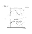
- FIGS. 11 to 14 are diagrams illustrating a second detailed example of steps S 40 and S 50 in FIG. 5 .
- the example shown in the figures shows a case where an assumed shape (transition line) is a curved line, as shown in FIG. 11( a ) , and is indicated by a function (first function).
- the demand transition setting unit 140 divides the assumed shape in the time unit ⁇ t using the first function, for discretization.
- the demand transition setting unit 140 adds a negative first constant to the discretized first function.
- the demand transition setting unit 140 determines the first constant so that the first function is smaller than 0 over the entire target period.
- the first constant is a value obtained by multiplying a maximum value of the first function in the target period by ⁇ 1, or a value larger than the former value in a negative direction.
- the demand transition setting unit 140 determines the power demand transition information so that the sum of the squares of differences between the first function and the power demand transition information becomes minimum. Specifically, the demand transition setting unit 140 calculates a difference L t between the first function indicating the assumed shape and the power demand transition information in each discretized section. Then, the demand transition setting unit 140 determines the power demand transition information so that the sum of the squares of the differences L t becomes a minimum value. This process is expressed as a formula as follows. min: ⁇ ( W ( t ) ⁇ f ′( t )) 2
- W(t) represents the power demand transition information, which is a discretized function (second function)
- f′(t) represents the first function after addition of the first constant. Further, (W(t) ⁇ f′(t)) becomes L t .
- FIG. 15 is a diagram illustrating a result of the process shown in FIGS. 11 to 14 .
- the power supply schedule for the power network 44 is set to be included in the region between the first power demand transition information and the second power transition information.
- the first power demand transition information is based on the maximum value of electrical energy capable of being accumulated by the plural charging stations 22 within the target period
- the second power demand transition information is based on electrical energy that should be accumulated by the plural charging stations 22 within the target period.
- the power supply schedule for the power network 44 becomes a realistic schedule as long as it is included in the region between the first power demand transition information and the second power transition information.
- the demand transition setting unit 140 determines the first constant so that the first function is smaller than 0 over the entire target period.
- the demand transition setting unit 140 determines the first constant so that the first function is smaller than 0 over the entire target period.
- the first constant shown in FIG. 12 may not have a value where the entirety of the first function becomes negative.
- the first constant may be a value where the first function becomes negative in a certain section. In this case, similarly, the calculation amount of the process shown in FIGS. 13 and 14 decreases.
- the operation startable time point, the operation end target time point, and the necessary operation time may be calculated using day-of-the-week information, month information, humidity, battery temperature, and information of the rechargeable battery type (for example, vehicle type information) in addition to the operation history of each of the charging stations 22 .
- FIG. 17 is a diagram illustrating a usage environment of an information processing apparatus 10 according to a third embodiment.
- the usage environment of the third embodiment is the same as that of the information processing apparatus 10 according to the second embodiment except for the following points.
- plural information processing apparatuses 10 are provided with respect to one schedule management apparatus 40 .
- the plural information processing apparatuses 10 are managed by different managers. Further, the plural information processing apparatuses 10 manage different charging stations 22 .
- the charging stations 22 are all connected to the same power network 44 .
- FIG. 18 is a diagram illustrating an operation of the information processing apparatus 10 according to the present embodiment.
- the information processing apparatus 10 according to the present embodiment performs the same process as that of the information processing apparatus 10 according to the second embodiment in that the demand transition setting unit 140 performs the following processes.
- the demand transition setting unit 140 calculates first power demand transition information and second power transition information so that transition in the electrical energy demand follows a function obtained by multiplying the first function which is shape information by a second constant.
- the demand transition setting unit 140 determines the power demand transition information so that the sum of absolute values of differences between the first function and the power demand transition information in a state where a linear function of which a coefficient is negative is added to the first function after multiplication of the second constant becomes minimum.
- the second constant is a constant smaller than 1.
- W t represents a discretized function (second function) indicating power demand transition information. Further, (W t ⁇ f′(t, b)) corresponds to L t shown in FIG. 13 .
- the power transition information that is calculated by each of the plural information processing apparatuses 10 by the second constant b becomes a shape fitted to the assumed shape.
- the power transition information of each of the plural information processing apparatuses 10 is added, a shape following the first function, that is, the assumed shape is formed.
- the same effects as those of the second embodiment can be obtained. Further, even if a change different from that predicted occurs in the electrical energy demand managed by a certain information processing apparatus 10 , the influence on the entire electrical energy demand is small.
- the plural charging stations 22 connected to one power network 44 are managed by the plural managers, it is considered that different time periods are allocated to the respective managers.
- the power transition information is set to follow the function obtained by multiplying the first function indicating the assumed shape by the second constant b smaller than 1.
Landscapes
- Engineering & Computer Science (AREA)
- Power Engineering (AREA)
- Business, Economics & Management (AREA)
- Mechanical Engineering (AREA)
- Transportation (AREA)
- Physics & Mathematics (AREA)
- General Physics & Mathematics (AREA)
- Health & Medical Sciences (AREA)
- Economics (AREA)
- Automation & Control Theory (AREA)
- Electromagnetism (AREA)
- Radar, Positioning & Navigation (AREA)
- Water Supply & Treatment (AREA)
- Marketing (AREA)
- Strategic Management (AREA)
- Tourism & Hospitality (AREA)
- General Business, Economics & Management (AREA)
- Theoretical Computer Science (AREA)
- Primary Health Care (AREA)
- General Health & Medical Sciences (AREA)
- Public Health (AREA)
- Human Resources & Organizations (AREA)
- General Engineering & Computer Science (AREA)
- Supply And Distribution Of Alternating Current (AREA)
- Charge And Discharge Circuits For Batteries Or The Like (AREA)
- Management, Administration, Business Operations System, And Electronic Commerce (AREA)
- Electric Propulsion And Braking For Vehicles (AREA)
- Remote Monitoring And Control Of Power-Distribution Networks (AREA)
Abstract
Description
- [Patent Document 1] Japanese Unexamined Patent Publication No. 2009-124885
- [Patent Document 2] PCT Japanese Translation Patent Publication No. 2010-512727
- [Non-Patent Document 1] Ninomiya et al, IEEJ Power and Energy Technical Meeting Collected Lectures (2011), Lecture No. P40, pp. 83-84, Aug. 30-Sep. 1, 2011, “Denki jidosha wo mochiita taiyoko hatsuden no shutsuryoku hendo yokusei no ichi kosatsu”
- [Non-Patent Document 2] H. Yano et al, ISGT, pp. 156-162, 2012, “A Novel Charging-Time Control Method for Numerous EVs based on a Period Weighted Prescheduling for Power Supply and Demand Balancing”
min: Σ(W(t)−f′(t))2
f′(t,b)=bf(t)−at
min: Σ(W t −f′(t,b))2
Claims (28)
Applications Claiming Priority (3)
| Application Number | Priority Date | Filing Date | Title |
|---|---|---|---|
| JP2012-213745 | 2012-09-27 | ||
| JP2012213745 | 2012-09-27 | ||
| PCT/JP2013/075459 WO2014050735A1 (en) | 2012-09-27 | 2013-09-20 | Information processing device, power-consuming body, information processing method, and program |
Publications (2)
| Publication Number | Publication Date |
|---|---|
| US20150220098A1 US20150220098A1 (en) | 2015-08-06 |
| US9946286B2 true US9946286B2 (en) | 2018-04-17 |
Family
ID=50388139
Family Applications (1)
| Application Number | Title | Priority Date | Filing Date |
|---|---|---|---|
| US14/429,494 Expired - Fee Related US9946286B2 (en) | 2012-09-27 | 2013-09-20 | Information processing apparatus, power-consuming body, information processing method, and program |
Country Status (4)
| Country | Link |
|---|---|
| US (1) | US9946286B2 (en) |
| EP (1) | EP2903115A4 (en) |
| JP (1) | JP6350284B2 (en) |
| WO (1) | WO2014050735A1 (en) |
Families Citing this family (5)
| Publication number | Priority date | Publication date | Assignee | Title |
|---|---|---|---|---|
| US20110265982A1 (en) * | 2010-04-29 | 2011-11-03 | International Business Machines Corporation | Controlling coolant flow to multiple cooling units in a computer system |
| JP5954370B2 (en) * | 2014-07-31 | 2016-07-20 | ダイキン工業株式会社 | Equipment management device |
| JPWO2016084904A1 (en) * | 2014-11-28 | 2017-09-07 | 日本電気株式会社 | Power management apparatus, power management method, and program |
| JP7073665B2 (en) * | 2017-10-12 | 2022-05-24 | 富士通株式会社 | Scheduling program, scheduling method, scheduling device, and scheduling system |
| GB2613367B (en) * | 2021-12-01 | 2024-04-24 | Myenergi Ltd | A method of charging an auxiliary battery |
Citations (9)
| Publication number | Priority date | Publication date | Assignee | Title |
|---|---|---|---|---|
| US20090062967A1 (en) * | 2007-09-05 | 2009-03-05 | Consolidated Edison Company Of New York, Inc. | Hybrid vehicle recharging system and method of operation |
| JP2009124885A (en) | 2007-11-15 | 2009-06-04 | Chugoku Electric Power Co Inc:The | System for supporting adjustment of electric power supply and demand |
| JP2009165254A (en) | 2007-12-29 | 2009-07-23 | Advance Design Corp | Power adjustment system and power adjustment method |
| JP2010512727A (en) | 2006-12-11 | 2010-04-22 | ブイ2グリーン・インコーポレーテッド | Power consolidation system for distributed electricity resources |
| JP2010213502A (en) | 2009-03-11 | 2010-09-24 | Omron Corp | Charging controller, method, and program |
| US20110184587A1 (en) * | 2010-01-25 | 2011-07-28 | Flux Engineering, LLC. | System and Method for Trading Electrical or Other Portable Power or Energy Source |
| US20120123995A1 (en) | 2010-11-17 | 2012-05-17 | General Electrical Company | Power consumption compliance monitoring system and method |
| WO2012093638A1 (en) | 2011-01-06 | 2012-07-12 | 日本電気株式会社 | Charging control device, charging control method, and program |
| WO2012120736A1 (en) | 2011-03-04 | 2012-09-13 | 日本電気株式会社 | Charging control system |
-
2013
- 2013-09-20 WO PCT/JP2013/075459 patent/WO2014050735A1/en not_active Ceased
- 2013-09-20 JP JP2014538464A patent/JP6350284B2/en not_active Expired - Fee Related
- 2013-09-20 US US14/429,494 patent/US9946286B2/en not_active Expired - Fee Related
- 2013-09-20 EP EP13841546.8A patent/EP2903115A4/en not_active Withdrawn
Patent Citations (11)
| Publication number | Priority date | Publication date | Assignee | Title |
|---|---|---|---|---|
| JP2010512727A (en) | 2006-12-11 | 2010-04-22 | ブイ2グリーン・インコーポレーテッド | Power consolidation system for distributed electricity resources |
| US20090062967A1 (en) * | 2007-09-05 | 2009-03-05 | Consolidated Edison Company Of New York, Inc. | Hybrid vehicle recharging system and method of operation |
| JP2010539866A (en) | 2007-09-05 | 2010-12-16 | コンソリデイティッド エジソン カンパニー オブ ニューヨーク インコーポレイテッド | Hybrid vehicle recharging system and operation method |
| JP2009124885A (en) | 2007-11-15 | 2009-06-04 | Chugoku Electric Power Co Inc:The | System for supporting adjustment of electric power supply and demand |
| JP2009165254A (en) | 2007-12-29 | 2009-07-23 | Advance Design Corp | Power adjustment system and power adjustment method |
| JP2010213502A (en) | 2009-03-11 | 2010-09-24 | Omron Corp | Charging controller, method, and program |
| US20110184587A1 (en) * | 2010-01-25 | 2011-07-28 | Flux Engineering, LLC. | System and Method for Trading Electrical or Other Portable Power or Energy Source |
| US20120123995A1 (en) | 2010-11-17 | 2012-05-17 | General Electrical Company | Power consumption compliance monitoring system and method |
| JP2012110218A (en) | 2010-11-17 | 2012-06-07 | General Electric Co <Ge> | Power consumption compliance monitoring system and method |
| WO2012093638A1 (en) | 2011-01-06 | 2012-07-12 | 日本電気株式会社 | Charging control device, charging control method, and program |
| WO2012120736A1 (en) | 2011-03-04 | 2012-09-13 | 日本電気株式会社 | Charging control system |
Non-Patent Citations (6)
| Title |
|---|
| H. Yano et al, "A Novel Charging-Time Control Method for Numerous EVs based on a Period Weighted Prescheduling for Power Supply and Demand Balancing", ISGT, pp. 156-162, 2012. |
| International Search Report for PCT Application No. PCT/JP2013/075459, dated Oct. 15, 2013. |
| Japanese Office Action for JP Application No. 2014-538464 dated Oct. 10, 2017 with English Translation. |
| Machine translation of JP 2012-080748, Takada Takayuki, In-Vehicle Navigation Device and Charging/Discharging Control Method of In-Vehicle Battery, Apr. 19, 2012, 11 pages. * |
| Ninomiya et al, "Denki jidosha wo mochiita taiyoko hatsuden no shutsuryoku hendo yokusei no. ichi kosatsu", IEEJ Power and Energy Technical Meeting Collected Lectures (2011), Lecture No. P40, pp. 83-84, Aug. 30-Sep. 1, 2011. |
| Yano et al., A Novel Charging-Time Control Method for Numerous EVs based on a Period Weighted Prescheduling for Power Supply and Demand Balancing, Jan. 20, 2012, 6 pages. * |
Also Published As
| Publication number | Publication date |
|---|---|
| EP2903115A4 (en) | 2016-06-01 |
| EP2903115A1 (en) | 2015-08-05 |
| US20150220098A1 (en) | 2015-08-06 |
| WO2014050735A1 (en) | 2014-04-03 |
| JP6350284B2 (en) | 2018-07-04 |
| JPWO2014050735A1 (en) | 2016-08-22 |
Similar Documents
| Publication | Publication Date | Title |
|---|---|---|
| Jin et al. | Optimized electric vehicle charging with intermittent renewable energy sources | |
| CN108146263B (en) | Power storage system, transmission equipment, and control method of power storage system | |
| CN108399578B (en) | Battery changing station service capability pre-estimation method and device | |
| JP6706877B2 (en) | Power management control system | |
| JPWO2017199604A1 (en) | Control device, control method, and power storage control device | |
| JP2012075243A (en) | Battery management system | |
| US9780565B2 (en) | System and method for controlling frequency | |
| US9941723B2 (en) | Power management system that changes the operating conditions of a battery charger | |
| JP6179512B2 (en) | Charging system control device, charging system, program, and control method | |
| EP3016237A1 (en) | Method for controlling charging power, system for controlling charging power, and program | |
| CN103354969B (en) | Rapid charging system, control device, method and program for controlling storage capacity | |
| CN106887086A (en) | Mobile charging equipment, mobile charging system and mobile charging method | |
| US20150220098A1 (en) | Information processing apparatus, power-consuming body, information processing method, and program | |
| CN117794776A (en) | Charging control and scheduling of electric vehicles and related systems and methods | |
| JP7648778B2 (en) | Demand Response Management for Battery Charging Systems | |
| US9881270B2 (en) | Information processing device, power-demanding object, information processing method, and non-transitory storage medium | |
| CN114597925A (en) | A flexible expansion method, flexible expansion device and storage medium | |
| CN104272548B (en) | Power management device, power management system, and power management method | |
| Szűcs et al. | Implementation and simulation of a dynamic load balancing solution for EV charge points utilizing solar energy | |
| CN115352289A (en) | Charging information processing method and device, storage medium, module and controller | |
| Martel et al. | Economy-focused PHEV battery lifetime management through optimal fuel cell load sharing | |
| KR20180036972A (en) | Control of loads and energy sources based on future energy level decisions | |
| JP6206396B2 (en) | ADJUSTING DEVICE CONTROL SYSTEM, ADJUSTING DEVICE CONTROL METHOD, AND PROGRAM | |
| US20160241033A1 (en) | Control device, control method, and program | |
| JP2019097375A (en) | Power management device and program |
Legal Events
| Date | Code | Title | Description |
|---|---|---|---|
| AS | Assignment |
Owner name: NEC CORPORATION, JAPAN Free format text: ASSIGNMENT OF ASSIGNORS INTEREST;ASSIGNORS:HASHIMOTO, RYO;YANO, HITOSHI;SAKUMA, HISATO;AND OTHERS;REEL/FRAME:035204/0171 Effective date: 20150130 |
|
| STCF | Information on status: patent grant |
Free format text: PATENTED CASE |
|
| MAFP | Maintenance fee payment |
Free format text: PAYMENT OF MAINTENANCE FEE, 4TH YEAR, LARGE ENTITY (ORIGINAL EVENT CODE: M1551); ENTITY STATUS OF PATENT OWNER: LARGE ENTITY Year of fee payment: 4 |
|
| FEPP | Fee payment procedure |
Free format text: MAINTENANCE FEE REMINDER MAILED (ORIGINAL EVENT CODE: REM.); ENTITY STATUS OF PATENT OWNER: LARGE ENTITY |
|
| LAPS | Lapse for failure to pay maintenance fees |
Free format text: PATENT EXPIRED FOR FAILURE TO PAY MAINTENANCE FEES (ORIGINAL EVENT CODE: EXP.); ENTITY STATUS OF PATENT OWNER: LARGE ENTITY |
|
| STCH | Information on status: patent discontinuation |
Free format text: PATENT EXPIRED DUE TO NONPAYMENT OF MAINTENANCE FEES UNDER 37 CFR 1.362 |
|
| FP | Lapsed due to failure to pay maintenance fee |
Effective date: 20260417 |