US994249A - Key-ring. - Google Patents
Key-ring. Download PDFInfo
- Publication number
- US994249A US994249A US1910550427A US994249A US 994249 A US994249 A US 994249A US 1910550427 A US1910550427 A US 1910550427A US 994249 A US994249 A US 994249A
- Authority
- US
- United States
- Prior art keywords
- sleeve
- ring
- spring
- key
- shoulder
- Prior art date
- Legal status (The legal status is an assumption and is not a legal conclusion. Google has not performed a legal analysis and makes no representation as to the accuracy of the status listed.)
- Expired - Lifetime
Links
- 238000010276 construction Methods 0.000 description 1
- 238000004519 manufacturing process Methods 0.000 description 1
- 229920000136 polysorbate Polymers 0.000 description 1
Images
Classifications
-
- A—HUMAN NECESSITIES
- A44—HABERDASHERY; JEWELLERY
- A44B—BUTTONS, PINS, BUCKLES, SLIDE FASTENERS, OR THE LIKE
- A44B15/00—Key-rings
-
- Y—GENERAL TAGGING OF NEW TECHNOLOGICAL DEVELOPMENTS; GENERAL TAGGING OF CROSS-SECTIONAL TECHNOLOGIES SPANNING OVER SEVERAL SECTIONS OF THE IPC; TECHNICAL SUBJECTS COVERED BY FORMER USPC CROSS-REFERENCE ART COLLECTIONS [XRACs] AND DIGESTS
- Y10—TECHNICAL SUBJECTS COVERED BY FORMER USPC
- Y10T—TECHNICAL SUBJECTS COVERED BY FORMER US CLASSIFICATION
- Y10T70/00—Locks
- Y10T70/80—Parts, attachments, accessories and adjuncts
- Y10T70/8432—For key-operated mechanism
- Y10T70/8676—Key holders
- Y10T70/8757—Releasable catches
Definitions
- This invention relates to key rings, and it has for its object the production of a ring on which the keys may be conveniently placed or from which they may be readily removed, and one that is securely locked against accidental oaening.
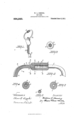
- Figure 1 is a perspective view of my key ring having keys thereon;
- Fig. 2 is a longitudinal section through the closing sleeve and the adjacent ends of the key ring;
- Figs. 3, 4, 5 and 6 are transverse sections taken through Fig.2on the lines 3-3, 4.4;, 5-5, and 66 respectively and looking in the directions of the respective arrows.
- A represents the main body of the key ring, upon which the keys B are placed.
- the part A of the ring is preferably shaped somewhat like the letter C, the ends 1 and 2 being in alinement but spaced apart to form a gap through which the keys may be inserted or removed.
- Mounted for sliding movement upon the end 2 of the ring is a sleeve 3, said sleeve normally closing the gap between the ends of the ring as shown in Fig. 2.
- the bore of the sleeve 3 is formed with two diameters, so
- the larger diameter fitting the end 2 of the ring as shown in Fig. 4:.
- the smaller diameter of the sleeve is made to fit a reduced portion 5 on the end of the part 1 of the ring, as shown in Figs. 2 and 5.
- a spring 6 Secured to the ring and extending over and beyond the end 2 of the latter is a spring 6, the same lying within a groove in the ring, the outer end of the spring being secured to the ring by closing in the groove about the spring, as shown in Fig 6.
- the end of the spring next the sleeve may have a slight movement in and out in said groove.
- the spring is formed of such a length as to substantially engage the shoulder 4: of the sleeve when the latter is moved into closed position, as seen 1n Fig. 2. The smaller bore of the slee e is locked in its closed position; but when the.
- the sleeve is turned until the groove 7 is opposite the spring, the sleeve may be drawn backwardly over the end 2 'of the ring, thus separating the sleeve from the end 1, so that the keys may be applied to or detached from the ring.
- That end of the sleeve adjacent the spring 6 is preferably notched at intervals, as shown at 9 in Fig. 3, said notches being adapted to receive the spring 6, the latter being preferably bowed at 10 so as to fit the concaved portion of the sleeve and rest in the grooves therein.
- the spring tends to lock the sleeve from rotation and will hold the same against accidental turning, which might bring the I groove 7 opposite the spring and permit the sleeve to slip backwardly over the end of the ring.
- the ring is closed and locked by simply drawing the same into the position shown in Fig. 2 and then turning the sleeve until the groove 7 is out of register with the spring when the spring itself locks the sleeve against accidental movement.
- a key ring having its ends in alinement but spaced apart, a sleeve mounted to slide on one end of the ring and adapted to close the space between the ends of the latter, a member secured to one end of the ring and projecting into the space between the said ends, and means on the sleeve adapted to substantially engage with said member when the sleeve is in its closed position so as'to lock the ring, the sleeve being adapted to be turned so as to bring said means outof alinem'ent with said member and thus unlock the sleeve so that the sleeve may be slid backwardly and thus open the space be tween the ends of the ring.
- a key ring having its ends in alinement but spaced apart, a sleeve normally closing the space between the ends of the ring, said sleeve having an internal shoulder with a groove therein, and a member projecting from that end of the ring opposite the shoulder, said member having its end adapted to substantially abut against said shoulder when the sleeve is in normal position, the sleeve being adapted to be rotated and to be drawn in the direction of the said member when the latter is opposite the said groove.
- a key ring having its ends in alinement but spaced apart, a sleeve mounted to slide on one end of the ring and adapted to eX- tend across the space between the ends of the latter so as to close the ring, an'internal shoulder within the bore of the sleeve, said shoulder having a groove therein and the bore of the sleeve being enlarged at one of its ends, said enlargement being provided with a series of grooves, and a spring secured to that end of the ring upon which the sleeve is adapted to slide, said spring extending into the sleeve and projecting beyond the end of the ring into substantial engagement with the shoulder of the sleeve, said spring being bowed so as to fit the enlargement of the bore of the sleeve and to engage with the grooves in said enlargement, whereby the sleeve may be held against accidental rotation.
- a key ring having its ends in alinement but spaced apart, a sleeve mounted to slide on one end of the ring and adapted to extend across the space between the ends of the latter so as to close the ring, the bore of the sleeve being of two diameters so as to form an internal shoulder within the sleeve, the sleeve having a groove extending from the shoulder along thesmaller part of the bore and the larger part of the bore being enlarged at one of its ends, said enlargement being provided With a series of grooves, and a spring secured to that end of the ring upon which the sleeve is adapted to slide, said spring extending into the sleeve and projecting beyond the end of the ring into substantial engagement with the shoulder of the sleeve, said spring being bowed so as to fit the enlargement of the bore of the sleeve and to engage with the grooves in said enlargement, whereby the sleeve may be held against accidental rotation.
Landscapes
- Adornments (AREA)
Description
W. L. DEMING.
' KEY RING.
APPLIOATIOH FILED MAR} 19, 1910.
Patente'dJune 6,1911.
WILLIAM L. DEMING, on SALEM, OHIO.
KEY-RING.
Specification of Letters Patent.
Patented June 6, 1911.
Application filed March 19, 1910. Serial No. 550,427.
To all whom t'tmay concern.
Be it known that I, WILLIAM L. DEMING, a citizen of the United States, residing at Salem, in the county of Columbiana and State of Ohio, have invented a certain new and useful Improvement in Key-Rings, of which the following is a full, clear, and exact description, reference being had to the accompanying drawings.
This invention relates to key rings, and it has for its object the production of a ring on which the keys may be conveniently placed or from which they may be readily removed, and one that is securely locked against accidental oaening.
In the drawings forming a part hereof, Figure 1 is a perspective view of my key ring having keys thereon; Fig. 2 is a longitudinal section through the closing sleeve and the adjacent ends of the key ring; Figs. 3, 4, 5 and 6 are transverse sections taken through Fig.2on the lines 3-3, 4.4;, 5-5, and 66 respectively and looking in the directions of the respective arrows.
Taking up a fuller description by the use of reference characters, A represents the main body of the key ring, upon which the keys B are placed. The part A of the ring is preferably shaped somewhat like the letter C, the ends 1 and 2 being in alinement but spaced apart to form a gap through which the keys may be inserted or removed. Mounted for sliding movement upon the end 2 of the ring is a sleeve 3, said sleeve normally closing the gap between the ends of the ring as shown in Fig. 2. The bore of the sleeve 3 is formed with two diameters, so
as to provide a shoulder at 4, the larger diameter fitting the end 2 of the ring, as shown in Fig. 4:. The smaller diameter of the sleeve is made to fit a reduced portion 5 on the end of the part 1 of the ring, as shown in Figs. 2 and 5.
Secured to the ring and extending over and beyond the end 2 of the latter is a spring 6, the same lying within a groove in the ring, the outer end of the spring being secured to the ring by closing in the groove about the spring, as shown in Fig 6. As thus constructed, the end of the spring next the sleeve may have a slight movement in and out in said groove. The spring is formed of such a length as to substantially engage the shoulder 4: of the sleeve when the latter is moved into closed position, as seen 1n Fig. 2. The smaller bore of the slee e is locked in its closed position; but when the.
sleeve is turned until the groove 7 is opposite the spring, the sleeve may be drawn backwardly over the end 2 'of the ring, thus separating the sleeve from the end 1, so that the keys may be applied to or detached from the ring.
That end of the sleeve adjacent the spring 6 is preferably notched at intervals, as shown at 9 in Fig. 3, said notches being adapted to receive the spring 6, the latter being preferably bowed at 10 so as to fit the concaved portion of the sleeve and rest in the grooves therein. By this construction, the spring tends to lock the sleeve from rotation and will hold the same against accidental turning, which might bring the I groove 7 opposite the spring and permit the sleeve to slip backwardly over the end of the ring. The ring is closed and locked by simply drawing the same into the position shown in Fig. 2 and then turning the sleeve until the groove 7 is out of register with the spring when the spring itself locks the sleeve against accidental movement.
Having thus described my invention, what I claim is 1. A key ring having its ends in alinement but spaced apart, a sleeve mounted to slide on one end of the ring and adapted to close the space between the ends of the latter, a member secured to one end of the ring and projecting into the space between the said ends, and means on the sleeve adapted to substantially engage with said member when the sleeve is in its closed position so as'to lock the ring, the sleeve being adapted to be turned so as to bring said means outof alinem'ent with said member and thus unlock the sleeve so that the sleeve may be slid backwardly and thus open the space be tween the ends of the ring.
2. A key ring having its ends in alinement but spaced apart, a sleeve normally closing the space between the ends of the ring, said sleeve having an internal shoulder with a groove therein, and a member projecting from that end of the ring opposite the shoulder, said member having its end adapted to substantially abut against said shoulder when the sleeve is in normal position, the sleeve being adapted to be rotated and to be drawn in the direction of the said member when the latter is opposite the said groove.
3. A key ring having its ends in alinement but spaced apart, a sleeve mounted to slide on one end of the ring and adapted to eX- tend across the space between the ends of the latter so as to close the ring, an'internal shoulder within the bore of the sleeve, said shoulder having a groove therein and the bore of the sleeve being enlarged at one of its ends, said enlargement being provided with a series of grooves, and a spring secured to that end of the ring upon which the sleeve is adapted to slide, said spring extending into the sleeve and projecting beyond the end of the ring into substantial engagement with the shoulder of the sleeve, said spring being bowed so as to fit the enlargement of the bore of the sleeve and to engage with the grooves in said enlargement, whereby the sleeve may be held against accidental rotation.
4. A key ring having its ends in alinement but spaced apart, a sleeve mounted to slide on one end of the ring and adapted to extend across the space between the ends of the latter so as to close the ring, the bore of the sleeve being of two diameters so as to form an internal shoulder within the sleeve, the sleeve having a groove extending from the shoulder along thesmaller part of the bore and the larger part of the bore being enlarged at one of its ends, said enlargement being provided With a series of grooves, and a spring secured to that end of the ring upon which the sleeve is adapted to slide, said spring extending into the sleeve and projecting beyond the end of the ring into substantial engagement with the shoulder of the sleeve, said spring being bowed so as to fit the enlargement of the bore of the sleeve and to engage with the grooves in said enlargement, whereby the sleeve may be held against accidental rotation.
In testimony whereof, I hereunto aflix my signature in the presence of two witnesses.
WILLIAM L. DEMING.
Witnesses:
S. E. FoU'rs, BRENNAN B. l/VEs'r.
Copies of this patent may be obtained for five cents each, by addressing the Commissioner of Patents, Washington, D. C.
Priority Applications (1)
| Application Number | Priority Date | Filing Date | Title |
|---|---|---|---|
| US1910550427 US994249A (en) | 1910-03-19 | 1910-03-19 | Key-ring. |
Applications Claiming Priority (1)
| Application Number | Priority Date | Filing Date | Title |
|---|---|---|---|
| US1910550427 US994249A (en) | 1910-03-19 | 1910-03-19 | Key-ring. |
Publications (1)
| Publication Number | Publication Date |
|---|---|
| US994249A true US994249A (en) | 1911-06-06 |
Family
ID=3062582
Family Applications (1)
| Application Number | Title | Priority Date | Filing Date |
|---|---|---|---|
| US1910550427 Expired - Lifetime US994249A (en) | 1910-03-19 | 1910-03-19 | Key-ring. |
Country Status (1)
| Country | Link |
|---|---|
| US (1) | US994249A (en) |
-
1910
- 1910-03-19 US US1910550427 patent/US994249A/en not_active Expired - Lifetime
Similar Documents
| Publication | Publication Date | Title |
|---|---|---|
| US1056079A (en) | Handcuff. | |
| US1232733A (en) | Clasp. | |
| US457959A (en) | Permutation-lock | |
| US1021456A (en) | Permutation-padlock. | |
| US1092031A (en) | Key-ring lock. | |
| US600864A (en) | Charles glover | |
| US320792A (en) | Key-ring | |
| US903680A (en) | Permutation-padlock. | |
| US534262A (en) | Leopold haberer | |
| US53143A (en) | Improvement in shaft-couplings | |
| US1036992A (en) | Padlock. | |
| US1353026A (en) | Hook | |
| US410027A (en) | Padlock | |
| US1162955A (en) | Key-ring. | |
| US672174A (en) | Permutation-lock. | |
| US365263A (en) | Rod-coupling | |
| US509819A (en) | Corkscrew | |
| US1787401A (en) | Valve lock | |
| US323941A (en) | John kubler | |
| US1250668A (en) | Permutation-lock. | |
| US1411123A (en) | Lock | |
| US491102A (en) | Permutation-padlock | |
| US1084942A (en) | Burglar-proof key. | |
| US611982A (en) | Permutation-padlock | |
| US1093930A (en) | Spear for spring shade-rollers. |