US9940195B2 - Encryption of slice partials - Google Patents
Encryption of slice partials Download PDFInfo
- Publication number
- US9940195B2 US9940195B2 US15/718,200 US201715718200A US9940195B2 US 9940195 B2 US9940195 B2 US 9940195B2 US 201715718200 A US201715718200 A US 201715718200A US 9940195 B2 US9940195 B2 US 9940195B2
- Authority
- US
- United States
- Prior art keywords
- unit
- key pairing
- entities
- rebuilding
- even number
- Prior art date
- Legal status (The legal status is an assumption and is not a legal conclusion. Google has not performed a legal analysis and makes no representation as to the accuracy of the status listed.)
- Expired - Fee Related
Links
Images


Classifications
-
- G—PHYSICS
- G06—COMPUTING OR CALCULATING; COUNTING
- G06F—ELECTRIC DIGITAL DATA PROCESSING
- G06F11/00—Error detection; Error correction; Monitoring
- G06F11/07—Responding to the occurrence of a fault, e.g. fault tolerance
- G06F11/08—Error detection or correction by redundancy in data representation, e.g. by using checking codes
- G06F11/10—Adding special bits or symbols to the coded information, e.g. parity check, casting out 9's or 11's
- G06F11/1076—Parity data used in redundant arrays of independent storages, e.g. in RAID systems
-
- G—PHYSICS
- G06—COMPUTING OR CALCULATING; COUNTING
- G06F—ELECTRIC DIGITAL DATA PROCESSING
- G06F11/00—Error detection; Error correction; Monitoring
- G06F11/07—Responding to the occurrence of a fault, e.g. fault tolerance
- G06F11/14—Error detection or correction of the data by redundancy in operations
- G06F11/1402—Saving, restoring, recovering or retrying
-
- G—PHYSICS
- G06—COMPUTING OR CALCULATING; COUNTING
- G06F—ELECTRIC DIGITAL DATA PROCESSING
- G06F11/00—Error detection; Error correction; Monitoring
- G06F11/07—Responding to the occurrence of a fault, e.g. fault tolerance
- G06F11/16—Error detection or correction of the data by redundancy in hardware
- G06F11/20—Error detection or correction of the data by redundancy in hardware using active fault-masking, e.g. by switching out faulty elements or by switching in spare elements
- G06F11/2053—Error detection or correction of the data by redundancy in hardware using active fault-masking, e.g. by switching out faulty elements or by switching in spare elements where persistent mass storage functionality or persistent mass storage control functionality is redundant
- G06F11/2089—Redundant storage control functionality
-
- G—PHYSICS
- G06—COMPUTING OR CALCULATING; COUNTING
- G06F—ELECTRIC DIGITAL DATA PROCESSING
- G06F12/00—Accessing, addressing or allocating within memory systems or architectures
- G06F12/14—Protection against unauthorised use of memory or access to memory
- G06F12/1408—Protection against unauthorised use of memory or access to memory by using cryptography
-
- G—PHYSICS
- G06—COMPUTING OR CALCULATING; COUNTING
- G06F—ELECTRIC DIGITAL DATA PROCESSING
- G06F21/00—Security arrangements for protecting computers, components thereof, programs or data against unauthorised activity
- G06F21/60—Protecting data
- G06F21/602—Providing cryptographic facilities or services
-
- G—PHYSICS
- G06—COMPUTING OR CALCULATING; COUNTING
- G06F—ELECTRIC DIGITAL DATA PROCESSING
- G06F21/00—Security arrangements for protecting computers, components thereof, programs or data against unauthorised activity
- G06F21/60—Protecting data
- G06F21/62—Protecting access to data via a platform, e.g. using keys or access control rules
- G06F21/6218—Protecting access to data via a platform, e.g. using keys or access control rules to a system of files or objects, e.g. local or distributed file system or database
- G06F21/6227—Protecting access to data via a platform, e.g. using keys or access control rules to a system of files or objects, e.g. local or distributed file system or database where protection concerns the structure of data, e.g. records, types, queries
-
- G—PHYSICS
- G06—COMPUTING OR CALCULATING; COUNTING
- G06F—ELECTRIC DIGITAL DATA PROCESSING
- G06F21/00—Security arrangements for protecting computers, components thereof, programs or data against unauthorised activity
- G06F21/60—Protecting data
- G06F21/64—Protecting data integrity, e.g. using checksums, certificates or signatures
-
- H—ELECTRICITY
- H04—ELECTRIC COMMUNICATION TECHNIQUE
- H04L—TRANSMISSION OF DIGITAL INFORMATION, e.g. TELEGRAPHIC COMMUNICATION
- H04L9/00—Cryptographic mechanisms or cryptographic arrangements for secret or secure communications; Network security protocols
- H04L9/08—Key distribution or management, e.g. generation, sharing or updating, of cryptographic keys or passwords
- H04L9/0816—Key establishment, i.e. cryptographic processes or cryptographic protocols whereby a shared secret becomes available to two or more parties, for subsequent use
- H04L9/085—Secret sharing or secret splitting, e.g. threshold schemes
-
- H—ELECTRICITY
- H04—ELECTRIC COMMUNICATION TECHNIQUE
- H04L—TRANSMISSION OF DIGITAL INFORMATION, e.g. TELEGRAPHIC COMMUNICATION
- H04L9/00—Cryptographic mechanisms or cryptographic arrangements for secret or secure communications; Network security protocols
- H04L9/08—Key distribution or management, e.g. generation, sharing or updating, of cryptographic keys or passwords
- H04L9/0861—Generation of secret information including derivation or calculation of cryptographic keys or passwords
-
- G—PHYSICS
- G06—COMPUTING OR CALCULATING; COUNTING
- G06F—ELECTRIC DIGITAL DATA PROCESSING
- G06F16/00—Information retrieval; Database structures therefor; File system structures therefor
- G06F16/20—Information retrieval; Database structures therefor; File system structures therefor of structured data, e.g. relational data
- G06F16/21—Design, administration or maintenance of databases
- G06F16/215—Improving data quality; Data cleansing, e.g. de-duplication, removing invalid entries or correcting typographical errors
-
- G06F17/30303—
-
- G—PHYSICS
- G06—COMPUTING OR CALCULATING; COUNTING
- G06F—ELECTRIC DIGITAL DATA PROCESSING
- G06F2221/00—Indexing scheme relating to security arrangements for protecting computers, components thereof, programs or data against unauthorised activity
- G06F2221/21—Indexing scheme relating to G06F21/00 and subgroups addressing additional information or applications relating to security arrangements for protecting computers, components thereof, programs or data against unauthorised activity
- G06F2221/2107—File encryption
Definitions
- U.S. Utility patent application Ser. No. 13/463,991 also claims priority pursuant to 35 U.S.C. ⁇ 120 as a continuation-in-part of U.S. Utility application Ser. No. 12/862,887, entitled “DISPERSED STORAGE NETWORK DATA SLICE INTEGRITY VERIFICATION,” filed Aug. 25, 2010, now U.S. Pat. No. 8,918,897, which is hereby incorporated herein by reference in its entirety and made part of the present U.S. Utility Patent Application for all purposes.
- This invention relates generally to computer networks and more particularly to dispersing error encoded data.
- Computing devices are known to communicate data, process data, and/or store data. Such computing devices range from wireless smart phones, laptops, tablets, personal computers (PC), work stations, and video game devices, to data centers that support millions of web searches, stock trades, or on-line purchases every day.
- a computing device includes a central processing unit (CPU), a memory system, user input/output interfaces, peripheral device interfaces, and an interconnecting bus structure.
- a computer may effectively extend its CPU by using “cloud computing” to perform one or more computing functions (e.g., a service, an application, an algorithm, an arithmetic logic function, etc.) on behalf of the computer.
- cloud computing may be performed by multiple cloud computing resources in a distributed manner to improve the response time for completion of the service, application, and/or function.
- Hadoop is an open source software framework that supports distributed applications enabling application execution by thousands of computers.
- a computer may use “cloud storage” as part of its memory system.
- cloud storage enables a user, via its computer, to store files, applications, etc. on an Internet storage system.
- the Internet storage system may include a RAID (redundant array of independent disks) system and/or a dispersed storage system that uses an error correction scheme to encode data for storage.
- FIG. 1 is a schematic block diagram of an embodiment of a dispersed or distributed storage network (DSN) in accordance with the present invention
- FIG. 2 is a schematic block diagram of an embodiment of a computing core in accordance with the present invention.
- FIG. 3 is a schematic block diagram of an example of dispersed storage error encoding of data in accordance with the present invention.
- FIG. 4 is a schematic block diagram of a generic example of an error encoding function in accordance with the present invention.
- FIG. 5 is a schematic block diagram of a specific example of an error encoding function in accordance with the present invention.
- FIG. 6 is a schematic block diagram of an example of a slice name of an encoded data slice (EDS) in accordance with the present invention.
- FIG. 7 is a schematic block diagram of an example of dispersed storage error decoding of data in accordance with the present invention.
- FIG. 8 is a schematic block diagram of a generic example of an error decoding function in accordance with the present invention.
- FIG. 9A is a schematic block diagram of another embodiment of a computing system in accordance with the invention.
- FIG. 9B is a table illustrating an example of a dispersed storage (DS) unit key pair to DS unit key assignment table in accordance with the invention.
- DS dispersed storage
- FIG. 10 is a flowchart illustrating an example of generating an encrypted partial slice in accordance with the present invention.
- FIG. 11 is a flowchart illustrating another example of generating an encrypted partial slice in accordance with the present invention.
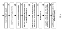
- FIG. 12 is a flowchart illustrating another example of generating an encrypted partial slice in accordance with the present invention.
- FIG. 1 is a schematic block diagram of an embodiment of a dispersed, or distributed, storage network (DSN) 10 that includes a plurality of computing devices 12 - 16 , a managing unit 18 , an integrity processing unit 20 , and a DSN memory 22 .
- the components of the DSN 10 are coupled to a network 24 , which may include one or more wireless and/or wire lined communication systems; one or more non-public intranet systems and/or public internet systems; and/or one or more local area networks (LAN) and/or wide area networks (WAN).
- LAN local area network
- WAN wide area network
- the DSN memory 22 includes a plurality of storage units 36 that may be located at geographically different sites (e.g., one in Chicago, one in Milwaukee, etc.), at a common site, or a combination thereof. For example, if the DSN memory 22 includes eight storage units 36 , each storage unit is located at a different site. As another example, if the DSN memory 22 includes eight storage units 36 , all eight storage units are located at the same site. As yet another example, if the DSN memory 22 includes eight storage units 36 , a first pair of storage units are at a first common site, a second pair of storage units are at a second common site, a third pair of storage units are at a third common site, and a fourth pair of storage units are at a fourth common site.
- geographically different sites e.g., one in Chicago, one in Milwaukee, etc.
- each storage unit is located at a different site.
- all eight storage units are located at the same site.
- a first pair of storage units are at a first common site
- a DSN memory 22 may include more or less than eight storage units 36 . Further note that each storage unit 36 includes a computing core (as shown in FIG. 2 , or components thereof) and a plurality of memory devices for storing dispersed error encoded data.
- Each of the computing devices 12 - 16 , the managing unit 18 , and the integrity processing unit 20 include a computing core 26 , which includes network interfaces 30 - 33 .
- Computing devices 12 - 16 may each be a portable computing device and/or a fixed computing device.
- a portable computing device may be a social networking device, a gaming device, a cell phone, a smart phone, a digital assistant, a digital music player, a digital video player, a laptop computer, a handheld computer, a tablet, a video game controller, and/or any other portable device that includes a computing core.
- a fixed computing device may be a computer (PC), a computer server, a cable set-top box, a satellite receiver, a television set, a printer, a fax machine, home entertainment equipment, a video game console, and/or any type of home or office computing equipment.
- each of the managing unit 18 and the integrity processing unit 20 may be separate computing devices, may be a common computing device, and/or may be integrated into one or more of the computing devices 12 - 16 and/or into one or more of the storage units 36 .
- Each interface 30 , 32 , and 33 includes software and hardware to support one or more communication links via the network 24 indirectly and/or directly.
- interface 30 supports a communication link (e.g., wired, wireless, direct, via a LAN, via the network 24 , etc.) between computing devices 14 and 16 .
- interface 32 supports communication links (e.g., a wired connection, a wireless connection, a LAN connection, and/or any other type of connection to/from the network 24 ) between computing devices 12 and 16 and the DSN memory 22 .
- interface 33 supports a communication link for each of the managing unit 18 and the integrity processing unit 20 to the network 24 .
- Computing devices 12 and 16 include a dispersed storage (DS) client module 34 , which enables the computing device to dispersed storage error encode and decode data (e.g., data 40 ) as subsequently described with reference to one or more of FIGS. 3-8 .
- computing device 16 functions as a dispersed storage processing agent for computing device 14 .
- computing device 16 dispersed storage error encodes and decodes data on behalf of computing device 14 .
- the DSN 10 is tolerant of a significant number of storage unit failures (the number of failures is based on parameters of the dispersed storage error encoding function) without loss of data and without the need for a redundant or backup copies of the data. Further, the DSN 10 stores data for an indefinite period of time without data loss and in a secure manner (e.g., the system is very resistant to unauthorized attempts at accessing the data).
- the managing unit 18 performs DS management services. For example, the managing unit 18 establishes distributed data storage parameters (e.g., vault creation, distributed storage parameters, security parameters, billing information, user profile information, etc.) for computing devices 12 - 14 individually or as part of a group of user devices. As a specific example, the managing unit 18 coordinates creation of a vault (e.g., a virtual memory block associated with a portion of an overall namespace of the DSN) within the DSN memory 22 for a user device, a group of devices, or for public access and establishes per vault dispersed storage (DS) error encoding parameters for a vault.
- distributed data storage parameters e.g., vault creation, distributed storage parameters, security parameters, billing information, user profile information, etc.
- the managing unit 18 coordinates creation of a vault (e.g., a virtual memory block associated with a portion of an overall namespace of the DSN) within the DSN memory 22 for a user device, a group of devices, or for public access and establishes
- the managing unit 18 facilitates storage of DS error encoding parameters for each vault by updating registry information of the DSN 10 , where the registry information may be stored in the DSN memory 22 , a computing device 12 - 16 , the managing unit 18 , and/or the integrity processing unit 20 .
- the managing unit 18 creates and stores user profile information (e.g., an access control list (ACL)) in local memory and/or within memory of the DSN memory 22 .
- the user profile information includes authentication information, permissions, and/or the security parameters.
- the security parameters may include encryption/decryption scheme, one or more encryption keys, key generation scheme, and/or data encoding/decoding scheme.
- the managing unit 18 creates billing information for a particular user, a user group, a vault access, public vault access, etc. For instance, the managing unit 18 tracks the number of times a user accesses a non-public vault and/or public vaults, which can be used to generate a per-access billing information. In another instance, the managing unit 18 tracks the amount of data stored and/or retrieved by a user device and/or a user group, which can be used to generate a per-data-amount billing information.
- the managing unit 18 performs network operations, network administration, and/or network maintenance.
- Network operations includes authenticating user data allocation requests (e.g., read and/or write requests), managing creation of vaults, establishing authentication credentials for user devices, adding/deleting components (e.g., user devices, storage units, and/or computing devices with a DS client module 34 ) to/from the DSN 10 , and/or establishing authentication credentials for the storage units 36 .
- Network administration includes monitoring devices and/or units for failures, maintaining vault information, determining device and/or unit activation status, determining device and/or unit loading, and/or determining any other system level operation that affects the performance level of the DSN 10 .
- Network maintenance includes facilitating replacing, upgrading, repairing, and/or expanding a device and/or unit of the DSN 10 .
- the integrity processing unit 20 performs rebuilding of ‘bad’ or missing encoded data slices.
- the integrity processing unit 20 performs rebuilding by periodically attempting to retrieve/list encoded data slices, and/or slice names of the encoded data slices, from the DSN memory 22 .
- retrieved encoded slices they are checked for errors due to data corruption, outdated version, etc. If a slice includes an error, it is flagged as a ‘bad’ slice.
- encoded data slices that were not received and/or not listed they are flagged as missing slices.
- Bad and/or missing slices are subsequently rebuilt using other retrieved encoded data slices that are deemed to be good slices to produce rebuilt slices.
- the rebuilt slices are stored in the DSN memory 22 .
- FIG. 2 is a schematic block diagram of an embodiment of a computing core 26 that includes a processing module 50 , a memory controller 52 , main memory 54 , a video graphics processing unit 55 , an input/output (TO) controller 56 , a peripheral component interconnect (PCI) interface 58 , an IO interface module 60 , at least one IO device interface module 62 , a read only memory (ROM) basic input output system (BIOS) 64 , and one or more memory interface modules.
- a processing module 50 a memory controller 52 , main memory 54 , a video graphics processing unit 55 , an input/output (TO) controller 56 , a peripheral component interconnect (PCI) interface 58 , an IO interface module 60 , at least one IO device interface module 62 , a read only memory (ROM) basic input output system (BIOS) 64 , and one or more memory interface modules.
- a processing module 50 includes a memory controller 52 , main memory 54 , a video graphics processing unit 55 , an
- the one or more memory interface module(s) includes one or more of a universal serial bus (USB) interface module 66 , a host bus adapter (HBA) interface module 68 , a network interface module 70 , a flash interface module 72 , a hard drive interface module 74 , and a DSN interface module 76 .
- USB universal serial bus
- HBA host bus adapter
- the DSN interface module 76 functions to mimic a conventional operating system (OS) file system interface (e.g., network file system (NFS), flash file system (FFS), disk file system (DFS), file transfer protocol (FTP), web-based distributed authoring and versioning (WebDAV), etc.) and/or a block memory interface (e.g., small computer system interface (SCSI), internet small computer system interface (iSCSI), etc.).
- OS operating system
- the DSN interface module 76 and/or the network interface module 70 may function as one or more of the interface 30 - 33 of FIG. 1 .
- the IO device interface module 62 and/or the memory interface modules 66 - 76 may be collectively or individually referred to as IO ports.
- FIG. 3 is a schematic block diagram of an example of dispersed storage error encoding of data.
- a computing device 12 or 16 When a computing device 12 or 16 has data to store it disperse storage error encodes the data in accordance with a dispersed storage error encoding process based on dispersed storage error encoding parameters.
- the dispersed storage error encoding parameters include an encoding function (e.g., information dispersal algorithm, Reed-Solomon, Cauchy Reed-Solomon, systematic encoding, non-systematic encoding, on-line codes, etc.), a data segmenting protocol (e.g., data segment size, fixed, variable, etc.), and per data segment encoding values.
- an encoding function e.g., information dispersal algorithm, Reed-Solomon, Cauchy Reed-Solomon, systematic encoding, non-systematic encoding, on-line codes, etc.
- a data segmenting protocol e.g., data segment size
- the per data segment encoding values include a total, or pillar width, number (T) of encoded data slices per encoding of a data segment (i.e., in a set of encoded data slices); a decode threshold number (D) of encoded data slices of a set of encoded data slices that are needed to recover the data segment; a read threshold number (R) of encoded data slices to indicate a number of encoded data slices per set to be read from storage for decoding of the data segment; and/or a write threshold number (W) to indicate a number of encoded data slices per set that must be accurately stored before the encoded data segment is deemed to have been properly stored.
- T total, or pillar width, number
- D decode threshold number
- R read threshold number
- W write threshold number
- the dispersed storage error encoding parameters may further include slicing information (e.g., the number of encoded data slices that will be created for each data segment) and/or slice security information (e.g., per encoded data slice encryption, compression, integrity checksum, etc.).
- slicing information e.g., the number of encoded data slices that will be created for each data segment
- slice security information e.g., per encoded data slice encryption, compression, integrity checksum, etc.
- the encoding function has been selected as Cauchy Reed-Solomon (a generic example is shown in FIG. 4 and a specific example is shown in FIG. 5 );
- the data segmenting protocol is to divide the data object into fixed sized data segments; and the per data segment encoding values include: a pillar width of 5, a decode threshold of 3, a read threshold of 4, and a write threshold of 4.
- the computing device 12 or 16 divides the data (e.g., a file (e.g., text, video, audio, etc.), a data object, or other data arrangement) into a plurality of fixed sized data segments (e.g., 1 through Y of a fixed size in range of Kilo-bytes to Tera-bytes or more).
- the number of data segments created is dependent of the size of the data and the data segmenting protocol.
- FIG. 4 illustrates a generic Cauchy Reed-Solomon encoding function, which includes an encoding matrix (EM), a data matrix (DM), and a coded matrix (CM).
- the size of the encoding matrix (EM) is dependent on the pillar width number (T) and the decode threshold number (D) of selected per data segment encoding values.
- EM encoding matrix
- T pillar width number
- D decode threshold number
- Z is a function of the number of data blocks created from the data segment and the decode threshold number (D).
- the coded matrix is produced by matrix multiplying the data matrix by the encoding matrix.
- FIG. 5 illustrates a specific example of Cauchy Reed-Solomon encoding with a pillar number (T) of five and decode threshold number of three.
- a first data segment is divided into twelve data blocks (D 1 -D 12 ).
- the coded matrix includes five rows of coded data blocks, where the first row of X 11 -X 14 corresponds to a first encoded data slice (EDS 1 _ 1 ), the second row of X 21 -X 24 corresponds to a second encoded data slice (EDS 2 _ 1 ), the third row of X 31 -X 34 corresponds to a third encoded data slice (EDS 3 _ 1 ), the fourth row of X 41 -X 44 corresponds to a fourth encoded data slice (EDS 4 _ 1 ), and the fifth row of X 51 -X 54 corresponds to a fifth encoded data slice (EDS 5 _ 1 ).
- the second number of the EDS designation corresponds to the data segment number.
- the computing device also creates a slice name (SN) for each encoded data slice (EDS) in the set of encoded data slices.
- a typical format for a slice name 80 is shown in FIG. 6 .
- the slice name (SN) 80 includes a pillar number of the encoded data slice (e.g., one of 1-T), a data segment number (e.g., one of 1-Y), a vault identifier (ID), a data object identifier (ID), and may further include revision level information of the encoded data slices.
- the slice name functions as, at least part of, a DSN address for the encoded data slice for storage and retrieval from the DSN memory 22 .
- the computing device 12 or 16 produces a plurality of sets of encoded data slices, which are provided with their respective slice names to the storage units for storage.
- the first set of encoded data slices includes EDS 1 _ 1 through EDS 5 _ 1 and the first set of slice names includes SN 1 _ 1 through SN 5 _ 1 and the last set of encoded data slices includes EDS 1 _Y through EDS 5 _Y and the last set of slice names includes SN 1 _Y through SN 5 _Y.
- FIG. 7 is a schematic block diagram of an example of dispersed storage error decoding of a data object that was dispersed storage error encoded and stored in the example of FIG. 4 .
- the computing device 12 or 16 retrieves from the storage units at least the decode threshold number of encoded data slices per data segment. As a specific example, the computing device retrieves a read threshold number of encoded data slices.
- the computing device uses a decoding function as shown in FIG. 8 .
- the decoding function is essentially an inverse of the encoding function of FIG. 4 .
- the coded matrix includes a decode threshold number of rows (e.g., three in this example) and the decoding matrix in an inversion of the encoding matrix that includes the corresponding rows of the coded matrix. For example, if the coded matrix includes rows 1 , 2 , and 4 , the encoding matrix is reduced to rows 1 , 2 , and 4 , and then inverted to produce the decoding matrix.
- Convergent encryption techniques use a key derived from the data being encrypted, but can make data less secure in some circumstances. Two techniques can be applied to augment the security of the data, by giving up some storage efficiency.
- the first technique makes it more difficult to correctly guess a file by virtue of its length.
- This method examines the current file size, and adds some padding to the end until the size is that of the next highest rounded value.
- the rounded values might be calculated to never expand the data by more than 1%. This can be done by calculating (log(file_size)/log(1+1%)), rounding that value up to the next highest integer to get N, then calculating (1+1%) ⁇ N.
- the file can then be rounded up to that size by adding the appropriate amount of padding to mask its true size.
- the second approach to trade efficiency for increased security is to make a determination as to how easy it is to guess the content. This can be done by estimating the entropy of the files content (for example, determining the size of the file if it were compressed). If this compressed size (a rough estimate of the file's entropy) is less than a certain threshold, then instead of generating deriving the key from the data, the key can be generated randomly. A unique file tag (or one based on the content of the encrypted data) will be generated. Thus for certain files, convergent encryption is not used, e.g. when the files are small, and/or overly predictable, but convergent encryption is used for other files.
- FIG. 9A is a schematic block diagram of another embodiment of a computing system.
- a system includes a plurality of sites 1 - 4 that include, in totality, a set of dispersed storage (DS) units associated with a set of encoded data slices.
- DS dispersed storage
- Such a set of encoded data slices is produced by dispersed storage error encoding a data segment.
- Each such site of the plurality of sites 1 - 4 includes at least one DS unit of the set of DS units, wherein the at least one DS unit stores an depending on previous encoded data slice of the set of encoded data slices.
- site 1 includes DS units 1 - 2
- site 2 includes DS units 3 - 4
- site 3 includes DS units 5 - 6
- site 4 includes DS units 7 - 8 when a pillar width is 8.
- Rebuilding an encoded data slice to be rebuilt requires at least a decode threshold number of encoded data slices of a set of encoded data slices associated with the encoded data slice to be rebuilt.
- DS unit 2 requests a decode threshold number of encoded data slices from DS units 1 , 3 , 4 , 5 , and 6 when DS unit 2 is associated with an encoded data slice to be rebuilt and the decode threshold number is 5.
- Each DS unit of DS units 1 , 3 , 4 , 5 , and 6 sends a corresponding encoded data slice (e.g., DS unit 4 sends a pillar 4 encoded data slice) to DS unit 2 .
- DS unit 2 receives the decode threshold number of encoded data slices and dispersed storage error decodes the decode threshold number of encoded data slices to reproduce a data segment.
- DS unit 2 dispersed storage error encodes the data segment to produce the set of encoded data slices.
- DS unit 2 selects the encoded data slice associated with DS unit 2 (e.g., pillar 2 ) as a copy of the encoded data slice to be rebuilt and stores the encoded data slice to be rebuilt.
- information leakage is possible as the decode threshold number of encoded data slices may be intercepted when sent to DS unit 2 .
- DS unit 2 requests a decode threshold number of slice partials from DS units 1 , 3 , 4 , 5 , and 6 when DS unit 2 is associated with the encoded data slice to be rebuilt and the decode threshold number is 5.
- Each DS unit of DS units 1 , 3 , 4 , 5 , and 6 generates a slice partial (e.g., DS unit 4 generates a pillar 4 slice partial) based on rebuilding parameters and an encoded data slice associated with the DS unit.
- Such rebuilding parameters includes one or more of a pillar width (e.g., 8 ), a decode threshold (e.g., 5 ), a pillar index to be rebuilt (e.g., pillar 2 ), the rebuilding participant list (e.g., DS units 1 , 3 , 4 , 5 , and 6 ), a rebuilding topology (e.g., DS unit 1 to DS unit 2 , DS unit 3 to DS unit 4 to DS unit 2 , DS unit 5 to DS unit 6 to DS unit 2 ), an encoding matrix, a DS unit pair key indicator, a DS unit key assignment, Diffie Hellman parameters, and an encryption algorithm indicator.
- a pillar width e.g. 8
- a decode threshold e.g., 5
- a pillar index to be rebuilt e.g., pillar 2
- the rebuilding participant list e.g., DS units 1 , 3 , 4 , 5 , and 6
- each DS unit of DS units 1 , 3 , 4 , 5 , and 6 encrypts the slice partial corresponding to the DS unit utilizing an encryption function, wherein the encryption function utilizes an encryption algorithm and one or more keys.
- Such an encryption algorithm includes performing an exclusive or (XOR) logical function on the slice partial and the one or more keys.
- Each key of the one or more keys may be utilized an even number of times by the DS unit and at least one other DS unit of DS units 1 , 3 , 4 , 5 , and 6 to enable subsequent decryption (e.g., XOR) when the decode threshold number of slice partials are combined to reproduce the encoded data slice to be rebuilt.
- each DS unit may utilize each possible key enabled for use by the DS unit.
- Each key of the one or more keys may be obtained by one or more of a retrieval, a message, and generation.
- DS unit 3 utilizes a shared secret key (K 3 - 5 ) shared between DS units 3 and 5
- DS unit 5 utilizes the shared secret key between DS units 3 and 5
- DS unit 4 utilizes a shared secret key (K 1 - 4 ) between DS units 1 and 4
- DS unit 6 utilizes a shared secret key (K 1 - 6 ) between DS units 1 and 6
- DS unit 1 utilizes the shared secret key between DS units 1 and 4 the shared secret key between DS units 1 and 6 in accordance with DS unit pair key indicators and a DS unit key assignment of the rebuilding parameters.
- Each DS unit may generate one or more keys associated with one or more DS unit pairings utilizing a Diffie Hellman method and Diffie Hellman parameters of the rebuilding parameters.
- DS unit 3 produces an encrypted slice partial in accordance with a formula: (K 3 - 5 ) ⁇ partial ( 2 , 3 ).
- DS unit 1 produces an encrypted slice partial in accordance with a formula: (K 1 - 4 ) ⁇ (K 1 - 6 ) ⁇ partial ( 2 , 1 ).
- DS unit 4 produces an encrypted slice partial in accordance with a formula: (K 1 - 4 ) ⁇ partial ( 2 , 4 ).
- each DS unit outputs an encrypted slice partial in accordance with a rebuilding topology of the rebuilding parameters.
- DS unit 1 sends the encrypted slice partial associated with DS unit 1 directly to DS unit 2 and DS unit 3 sends the encrypted slice partial associated with DS unit 3 to DS unit 4 (e.g., at the same site) in accordance with the rebuilding topology.
- DS unit 4 receives the encrypted slice partial associated with DS unit 3 and combines the encrypted slice partial associated with DS unit 3 with the encrypted slice partial associated with DS unit 4 in accordance with the rebuilding topology.
- DS unit 4 sends the combined encrypted slice partial to DS unit 2 in accordance with the rebuilding topology.
- DS unit 2 receives the decode threshold number of encrypted slice partials as one or more encrypted slice partials and/or one or more combined encrypted slice partials.
- DS unit 2 combines the one or more encrypted slice partials and/or the one or more combined encrypted slice partials utilizing a decryption algorithm (e.g., XOR) to reproduce the encoded data slice to be rebuilt.
- a decryption algorithm e.g., XOR
- Such a decryption algorithm cancels the even number utilization of each key to produce an XOR sequence of the slice partials.
- Such a XOR of the slice partials reproduces the encoded data slice to be rebuilt.
- information leakage is minimized as encoded data slices are not exposed and slice partials are encrypted.
- FIG. 9B is a table illustrating an example of a dispersed storage (DS) unit key pair to DS unit key assignment table.
- a table includes a DS unit pair key field, and a DS unit key assignment field.
- a DS unit pair key field includes a plurality of DS unit pair keys entries, wherein each key entry of the plurality of DS unit pair key entries includes two DS unit identifiers (IDs) of a corresponding DS unit pair enabled to utilize the key entry.
- IDs DS unit identifiers
- an entry including K 1 - 3 corresponds to a DS unit pair key to be utilized only by DS units 1 and 3 .
- key K 1 - 3 is generated by DS units 1 and 3 utilizing a Diffie Hellman approach.
- a number of entries of the DS unit pair key field may be based on a security requirement, a number of DS units, a rebuilding topology, and a network topology.
- Such a DS unit key assignment field includes two or more DS unit identifier (ID) fields corresponding to two or more DS units included in a DS unit storage set providing key assignments.
- An entry (e.g., “X”) associated with a DS unit signifies that the DS unit is assigned to utilize a corresponding DS unit pair key of a corresponding row of the table.
- two X entries in a column corresponding to DS unit 1 signifies that DS unit 1 is to utilize keys K 1 - 4 and key K 1 - 6 .
- Such key assignments may be assigned in many different ways in accordance with the rebuilding topology and assignment goals, wherein such assignment goals include one or more of a security goal, a performance goal, and a processing loading goal.
- assigned keys should not include a key that is shared between a DS unit pair when a first DS unit of the DS unit pair sends an encrypted slice partial to a second DS unit of the DS unit pair since information leakage may occur when the second DS unit combines the encrypted slice partials.
- each assigned key should be utilized and even number of times such that each assigned key cancels out (e.g., via an XOR function) when a requesting entity decodes encrypted slice partials to reproduce an encoded data slice to be rebuilt.
- a method to determine and utilize keys is discussed in greater detail with reference to FIGS. 10-12 .
- FIG. 10 is a flowchart illustrating an example of generating an encrypted partial slice.
- the method begins with step 90 , where a processing module, for example computing device 16 ( FIG. 1 ), storage unit 36 ( FIG. 1 ), or a DS unit 1 - 8 ( FIG. 9A ), receives a rebuilding request, for example from or on behalf of another DS unit.
- a processing module for example computing device 16 ( FIG. 1 ), storage unit 36 ( FIG. 1 ), or a DS unit 1 - 8 ( FIG. 9A ), receives a rebuilding request, for example from or on behalf of another DS unit.
- a rebuilding request includes one or more of rebuilding participant identifiers (IDs), Diffie Hellman parameters, a rebuilding topology, a number of keys to utilize indicator, a pillar index to rebuild indicator, a slice name list, a requesting entity identifier (ID), a key generation algorithm, a key generation algorithm ID, and rebuilding parameters.
- IDs rebuilding participant
- the processing module may validate the request by one or more of validating a signature, verifying that the requesting entity ID is associated with one or more slice names of the slice name list (e.g., authorized to rebuild), and validating that the rebuilding topology corresponds to a network topology and/or compares favorably to a functional approach to rebuilding.
- the method continues at the step 92 , where the processing module determines one or more key pairing entities. Such a determination may be based on one or more of the rebuilding topology, a security requirement, the rebuilding participant identifiers, and a bandwidth utilization requirement. For example, exclude use of a key pair where DS units associated with the key pair are long a same path of the rebuilding topology (e.g., to avoid a leakage).
- the method continues at the step 94 , where the processing module generates a shared secret key corresponding to each of the one or more key pairing entities.
- Such generation may include one or more of a lookup, receiving, and utilizing a Diffie Hellman approach (e.g., each DS unit of a DS unit pair utilizes the Diffie Hellman parameters to produce public values which are exchanged and utilized to produce the shared secret key).
- the method continues at the step 96 , where the processing module generates a slice partial based on a corresponding stored encoded data slice, rebuilding parameters, and information received in the rebuilding request.
- the method continues at the step where the processing module encrypts the slice partial with each of the shared secret keys to produce an encrypted slice partial.
- the processing module utilizes a XOR function to XOR each of the shared secret keys and the slice partial to produce the encrypted slice partial.
- the method continues at the step 100 of the processing module outputs the encrypted slice partial in accordance with the rebuilding topology.
- the processing module sends the encrypted slice partial to a DS unit assigned as an aggregator.
- the processing module sends the encrypted slice partial directly to a DS unit that is a requesting entity.
- FIG. 11 is a flowchart illustrating another example of generating an encrypted partial slice, which includes similar steps to FIG. 10 .
- the method begins with steps similar to those discussed with respect to FIG. 9 , where a processing module receives a rebuilding request ( 110 ) and determines one or more key pairing entities ( 112 ).
- the method continues at step 114 , where the processing module obtains a seed key for each of the one or more key pairing entities.
- Such obtaining can include at least one of retrieving the seed key and generating the seed key utilizing a Diffie Hellman approach (e.g., seed key substantially the same as a shared secret key of a DS unit pair key).
- the method continues at the step 116 where the processing module generates a temp key for each seed key.
- Such generation includes performing a hashing function on a sum of key elements.
- a hashing function includes one or more of a hash algorithm (e.g., message digest (MD)-5, secure hash algorithm (SHA)-1, SHA-256, SHA 512), a hash-based message authentication code (HMAC, e.g., HMAC-MD-5), and a mask generating function (MGF) to expand the temp key to a length substantially the same as a slice partial generated at step 118 .
- a hash algorithm e.g., message digest (MD)-5, secure hash algorithm (SHA)-1, SHA-256, SHA 512
- HMAC hash-based message authentication code
- MMF mask generating function
- a stream cipher with hash/HMAC output as an encryption key may be utilized to expand the temp key length, or a block cipher (e.g., advanced encryption standard AES, data encryption standard DES) using encryption mode such as output feedback (OFB), cipher feedback (CFB), counter mode (CTR) with hash/HMAC output as the encryption key.
- a block cipher e.g., advanced encryption standard AES, data encryption standard DES
- OFB output feedback
- CTR counter mode
- key elements includes one or more of the seed key, a slice name, a requesting entity ID, and a rebuilding participants list.
- temp key hashing function (seed key+slice name+slice revision+requesting entity ID+rebuilding participants).
- Such a temp key may change for each encoded data slice to be rebuilt and such a seed key may be utilized for multiple rebuilding sequences.
- the method continues at the step 120 where the processing module encrypts the slice partial generated at block 118 with each of the one or more temp keys utilizing an encryption algorithm to produce an encrypted slice partial.
- the processing module utilizes a XOR function as the encryption algorithm and performs the XOR function with each of the one or more temp keys and the slice partial to produce the encrypted slice partial.
- the method continues at the step 122 where the processing module outputs the encrypted slice partial to a requesting entity or to an aggregating DS unit in accordance with the rebuilding topology.
- every partial encrypted slice can be encrypted with every others participant's shared key.
- each partial must be encrypted a threshold number of times, by a threshold number of participants. In that case, CPU cost would likely increase as the square of the threshold.
- each partial is encrypted twice.
- the method begins with steps similar to some of the steps discussed with respect to FIG. 10 , where a processing module receives a rebuilding request ( 130 ).
- the method continues at the step 132 where the processing module determines key pairing requirements.
- key pairing requirements include one or more of a performance requirement, a security requirement, and a processor loading requirement.
- Such a determination may be based on one or more of the rebuilding request, a predetermination, a message, a dispersed storage network (DSN) performance indicator, a DSN security indicator, a vault identifier (ID), and a requester ID.
- DSN dispersed storage network
- ID vault identifier
- the processing module determines a lower than average processor loading requirement when the DSN performance indicator indicates that the DSN system is loaded more than average.
- the processing module determines a higher than average security requirement when the DSN security indicator indicates that higher security is required.
- the processing module determines candidate key pairing entities. Such a determination may be based on one or more of the key pairing requirements, a rebuilding topology, a security requirement, rebuilding participants, and a bandwidth utilization requirement. For example, the processing module may determine a lower than average number of candidate key pairing entities when the key pairing requirements includes a lower than average processor loading requirement. As another example, the processing module may determine a higher than average number of candidate key pairing entities when the key pairing requirements includes a higher than average security requirement.
- the method continues at the step 136 of the processing module selects one or more key pairing entities of the candidate key pairing entities based on the key pairing requirements. Such a selection may be based on one or more of optimizing a match of the key pairing requirements to an estimated performance an estimated security associated with a desired number of candidate key pairing entities. For example, the processing module selects a lower than average number of key pairing entities for better performance and selects a higher than average number of key pairing entities for better security. As another example, the processing module selects a key pairing entity for utilization of an associated key an even number of times amongst all dispersed storage (DS) units.
- DS dispersed storage
- the processing module selects a node ahead and a node behind a reference DS unit (e.g., associated with the processing module), wherein the node ahead, the DS unit, and the node behind are substantially sequenced in order in accordance with a rebuilding topology.
- the processing module selects two nodes ahead and two nodes behind.
- the method continues with the processing module generating a shared secret key corresponding to each of the one or more key pairing entities ( 138 ), generates a partial slice ( 140 ), encrypts the partial slice with each of the shared secret keys to produce an encrypted slice partial ( 142 ), and outputs the encrypted slice partial in accordance with a rebuilding topology ( 144 ).
- the terms “substantially” and “approximately” provides an industry-accepted tolerance for its corresponding term and/or relativity between items. Such an industry-accepted tolerance ranges from less than one percent to fifty percent and corresponds to, but is not limited to, component values, integrated circuit process variations, temperature variations, rise and fall times, and/or thermal noise. Such relativity between items ranges from a difference of a few percent to magnitude differences.
- the term(s) “configured to”, “operably coupled to”, “coupled to”, and/or “coupling” includes direct coupling between items and/or indirect coupling between items via an intervening item (e.g., an item includes, but is not limited to, a component, an element, a circuit, and/or a module) where, for an example of indirect coupling, the intervening item does not modify the information of a signal but may adjust its current level, voltage level, and/or power level.
- inferred coupling i.e., where one element is coupled to another element by inference
- the term “configured to”, “operable to”, “coupled to”, or “operably coupled to” indicates that an item includes one or more of power connections, input(s), output(s), etc., to perform, when activated, one or more its corresponding functions and may further include inferred coupling to one or more other items.
- the term “associated with”, includes direct and/or indirect coupling of separate items and/or one item being embedded within another item.
- the term “compares favorably”, indicates that a comparison between two or more items, signals, etc., provides a desired relationship. For example, when the desired relationship is that signal 1 has a greater magnitude than signal 2 , a favorable comparison may be achieved when the magnitude of signal 1 is greater than that of signal 2 or when the magnitude of signal 2 is less than that of signal 1 .
- the term “compares unfavorably”, indicates that a comparison between two or more items, signals, etc., fails to provide the desired relationship.
- processing module may be a single processing device or a plurality of processing devices.
- a processing device may be a microprocessor, micro-controller, digital signal processor, microcomputer, central processing unit, field programmable gate array, programmable logic device, state machine, logic circuitry, analog circuitry, digital circuitry, and/or any device that manipulates signals (analog and/or digital) based on hard coding of the circuitry and/or operational instructions.
- the processing module, module, processing circuit, and/or processing unit may be, or further include, memory and/or an integrated memory element, which may be a single memory device, a plurality of memory devices, and/or embedded circuitry of another processing module, module, processing circuit, and/or processing unit.
- a memory device may be a read-only memory, random access memory, volatile memory, non-volatile memory, static memory, dynamic memory, flash memory, cache memory, and/or any device that stores digital information.
- processing module, module, processing circuit, and/or processing unit includes more than one processing device, the processing devices may be centrally located (e.g., directly coupled together via a wired and/or wireless bus structure) or may be distributedly located (e.g., cloud computing via indirect coupling via a local area network and/or a wide area network). Further note that if the processing module, module, processing circuit, and/or processing unit implements one or more of its functions via a state machine, analog circuitry, digital circuitry, and/or logic circuitry, the memory and/or memory element storing the corresponding operational instructions may be embedded within, or external to, the circuitry comprising the state machine, analog circuitry, digital circuitry, and/or logic circuitry.
- the memory element may store, and the processing module, module, processing circuit, and/or processing unit executes, hard coded and/or operational instructions corresponding to at least some of the steps and/or functions illustrated in one or more of the Figures.
- Such a memory device or memory element can be included in an article of manufacture.
- a flow diagram may include a “start” and/or “continue” indication.
- the “start” and “continue” indications reflect that the steps presented can optionally be incorporated in or otherwise used in conjunction with other routines.
- start indicates the beginning of the first step presented and may be preceded by other activities not specifically shown.
- continue indicates that the steps presented may be performed multiple times and/or may be succeeded by other activities not specifically shown.
- a flow diagram indicates a particular ordering of steps, other orderings are likewise possible provided that the principles of causality are maintained.
- the one or more embodiments are used herein to illustrate one or more aspects, one or more features, one or more concepts, and/or one or more examples.
- a physical embodiment of an apparatus, an article of manufacture, a machine, and/or of a process may include one or more of the aspects, features, concepts, examples, etc. described with reference to one or more of the embodiments discussed herein.
- the embodiments may incorporate the same or similarly named functions, steps, modules, etc. that may use the same or different reference numbers and, as such, the functions, steps, modules, etc. may be the same or similar functions, steps, modules, etc. or different ones.
- signals to, from, and/or between elements in a figure of any of the figures presented herein may be analog or digital, continuous time or discrete time, and single-ended or differential.
- signals to, from, and/or between elements in a figure of any of the figures presented herein may be analog or digital, continuous time or discrete time, and single-ended or differential.
- a signal path is shown as a single-ended path, it also represents a differential signal path.
- a signal path is shown as a differential path, it also represents a single-ended signal path.
- module is used in the description of one or more of the embodiments.
- a module implements one or more functions via a device such as a processor or other processing device or other hardware that may include or operate in association with a memory that stores operational instructions.
- a module may operate independently and/or in conjunction with software and/or firmware.
- a module may contain one or more sub-modules, each of which may be one or more modules.
- a computer readable memory includes one or more memory elements.
- a memory element may be a separate memory device, multiple memory devices, or a set of memory locations within a memory device.
- Such a memory device may be a read-only memory, random access memory, volatile memory, non-volatile memory, static memory, dynamic memory, flash memory, cache memory, and/or any device that stores digital information.
- the memory device may be in a form a solid state memory, a hard drive memory, cloud memory, thumb drive, server memory, computing device memory, and/or other physical medium for storing digital information.
Landscapes
- Engineering & Computer Science (AREA)
- Theoretical Computer Science (AREA)
- Computer Security & Cryptography (AREA)
- Physics & Mathematics (AREA)
- General Engineering & Computer Science (AREA)
- General Physics & Mathematics (AREA)
- Computer Hardware Design (AREA)
- Health & Medical Sciences (AREA)
- Bioethics (AREA)
- General Health & Medical Sciences (AREA)
- Software Systems (AREA)
- Quality & Reliability (AREA)
- Computer Networks & Wireless Communication (AREA)
- Signal Processing (AREA)
- Databases & Information Systems (AREA)
- Storage Device Security (AREA)
Abstract
Description
Claims (17)
Priority Applications (1)
| Application Number | Priority Date | Filing Date | Title |
|---|---|---|---|
| US15/718,200 US9940195B2 (en) | 2010-08-25 | 2017-09-28 | Encryption of slice partials |
Applications Claiming Priority (4)
| Application Number | Priority Date | Filing Date | Title |
|---|---|---|---|
| US12/862,887 US8918897B2 (en) | 2009-11-24 | 2010-08-25 | Dispersed storage network data slice integrity verification |
| US201161493820P | 2011-06-06 | 2011-06-06 | |
| US13/463,991 US9842222B2 (en) | 2010-08-25 | 2012-05-04 | Securely rebuilding an encoded data slice |
| US15/718,200 US9940195B2 (en) | 2010-08-25 | 2017-09-28 | Encryption of slice partials |
Related Parent Applications (1)
| Application Number | Title | Priority Date | Filing Date |
|---|---|---|---|
| US13/463,991 Continuation-In-Part US9842222B2 (en) | 2010-08-25 | 2012-05-04 | Securely rebuilding an encoded data slice |
Publications (2)
| Publication Number | Publication Date |
|---|---|
| US20180018232A1 US20180018232A1 (en) | 2018-01-18 |
| US9940195B2 true US9940195B2 (en) | 2018-04-10 |
Family
ID=60941066
Family Applications (1)
| Application Number | Title | Priority Date | Filing Date |
|---|---|---|---|
| US15/718,200 Expired - Fee Related US9940195B2 (en) | 2010-08-25 | 2017-09-28 | Encryption of slice partials |
Country Status (1)
| Country | Link |
|---|---|
| US (1) | US9940195B2 (en) |
Cited By (1)
| Publication number | Priority date | Publication date | Assignee | Title |
|---|---|---|---|---|
| US11321323B2 (en) * | 2015-03-26 | 2022-05-03 | Nagravision S.A. | Method and system for searching for at least a specific datum in a user unit |
Families Citing this family (2)
| Publication number | Priority date | Publication date | Assignee | Title |
|---|---|---|---|---|
| US11451371B2 (en) * | 2019-10-30 | 2022-09-20 | Dell Products L.P. | Data masking framework for information processing system |
| CN114785620B (en) * | 2022-06-16 | 2022-09-02 | 国网浙江省电力有限公司金华供电公司 | Full-flow encryption method for audit data |
Citations (79)
| Publication number | Priority date | Publication date | Assignee | Title |
|---|---|---|---|---|
| US4092732A (en) | 1977-05-31 | 1978-05-30 | International Business Machines Corporation | System for recovering data stored in failed memory unit |
| US5454101A (en) | 1992-09-15 | 1995-09-26 | Universal Firmware Industries, Ltd. | Data storage system with set lists which contain elements associated with parents for defining a logical hierarchy and general record pointers identifying specific data sets |
| US5485474A (en) | 1988-02-25 | 1996-01-16 | The President And Fellows Of Harvard College | Scheme for information dispersal and reconstruction |
| US5774643A (en) | 1995-10-13 | 1998-06-30 | Digital Equipment Corporation | Enhanced raid write hole protection and recovery |
| US5802364A (en) | 1996-04-15 | 1998-09-01 | Sun Microsystems, Inc. | Metadevice driver rename/exchange technique for a computer system incorporating a plurality of independent device drivers |
| US5809285A (en) | 1995-12-21 | 1998-09-15 | Compaq Computer Corporation | Computer system having a virtual drive array controller |
| US5890156A (en) | 1996-05-02 | 1999-03-30 | Alcatel Usa, Inc. | Distributed redundant database |
| US5987622A (en) | 1993-12-10 | 1999-11-16 | Tm Patents, Lp | Parallel computer system including parallel storage subsystem including facility for correction of data in the event of failure of a storage device in parallel storage subsystem |
| US5991414A (en) | 1997-09-12 | 1999-11-23 | International Business Machines Corporation | Method and apparatus for the secure distributed storage and retrieval of information |
| US6012159A (en) | 1996-01-17 | 2000-01-04 | Kencast, Inc. | Method and system for error-free data transfer |
| US6058454A (en) | 1997-06-09 | 2000-05-02 | International Business Machines Corporation | Method and system for automatically configuring redundant arrays of disk memory devices |
| US6128277A (en) | 1997-10-01 | 2000-10-03 | California Inst Of Techn | Reliable array of distributed computing nodes |
| US6175571B1 (en) | 1994-07-22 | 2001-01-16 | Network Peripherals, Inc. | Distributed memory switching hub |
| US6256688B1 (en) | 1997-12-02 | 2001-07-03 | Casio Computer Co., Ltd. | Interface apparatus operable by using floppy disk drive |
| US6272658B1 (en) | 1997-10-27 | 2001-08-07 | Kencast, Inc. | Method and system for reliable broadcasting of data files and streams |
| US6301604B1 (en) | 1997-12-01 | 2001-10-09 | Matsushita Electric Industrial Co., Ltd. | Multimedia server |
| US6356949B1 (en) | 1999-01-29 | 2002-03-12 | Intermec Ip Corp. | Automatic data collection device that receives data output instruction from data consumer |
| US6366995B1 (en) | 1998-08-19 | 2002-04-02 | Acuid Corporation Limited | System and a method for defining transforms of memory device addresses |
| US6374336B1 (en) | 1997-12-24 | 2002-04-16 | Avid Technology, Inc. | Computer system and process for transferring multiple high bandwidth streams of data between multiple storage units and multiple applications in a scalable and reliable manner |
| US20020062422A1 (en) | 2000-11-18 | 2002-05-23 | International Business Machines Corporation | Method for rebuilding meta-data in a data storage system and a data storage system |
| US6415373B1 (en) | 1997-12-24 | 2002-07-02 | Avid Technology, Inc. | Computer system and process for transferring multiple high bandwidth streams of data between multiple storage units and multiple applications in a scalable and reliable manner |
| US6418539B1 (en) | 1995-05-25 | 2002-07-09 | Compaq Computer Corporation | Continuously available computer memory systems |
| US20020166079A1 (en) | 2001-01-29 | 2002-11-07 | Ulrich Thomas R. | Dynamic data recovery |
| US20030018927A1 (en) | 2001-07-23 | 2003-01-23 | Gadir Omar M.A. | High-availability cluster virtual server system |
| US20030037261A1 (en) | 2001-03-26 | 2003-02-20 | Ilumin Corporation | Secured content delivery system and method |
| US20030065617A1 (en) | 2001-06-30 | 2003-04-03 | Watkins Mark Robert | Method of billing for utilization of a data storage array, and an array controller therefor |
| US20030084020A1 (en) | 2000-12-22 | 2003-05-01 | Li Shu | Distributed fault tolerant and secure storage |
| US6571282B1 (en) | 1999-08-31 | 2003-05-27 | Accenture Llp | Block-based communication in a communication services patterns environment |
| US6609223B1 (en) | 1999-04-06 | 2003-08-19 | Kencast, Inc. | Method for packet-level fec encoding, in which on a source packet-by-source packet basis, the error correction contributions of a source packet to a plurality of wildcard packets are computed, and the source packet is transmitted thereafter |
| US20040024963A1 (en) | 2002-08-05 | 2004-02-05 | Nisha Talagala | Method and system for striping data to accommodate integrity metadata |
| US6718361B1 (en) | 2000-04-07 | 2004-04-06 | Network Appliance Inc. | Method and apparatus for reliable and scalable distribution of data files in distributed networks |
| US20040122917A1 (en) | 2002-12-18 | 2004-06-24 | Menon Jaishankar Moothedath | Distributed storage system for data-sharing among client computers running defferent operating system types |
| US6785783B2 (en) | 2000-11-30 | 2004-08-31 | International Business Machines Corporation | NUMA system with redundant main memory architecture |
| US20040215998A1 (en) | 2003-04-10 | 2004-10-28 | International Business Machines Corporation | Recovery from failures within data processing systems |
| US20040228493A1 (en) | 2003-05-14 | 2004-11-18 | Kenneth Ma | Method and system for disaster recovery of data from a storage device |
| US6826711B2 (en) | 2000-02-18 | 2004-11-30 | Avamar Technologies, Inc. | System and method for data protection with multidimensional parity |
| US6879596B1 (en) | 2001-04-11 | 2005-04-12 | Applied Micro Circuits Corporation | System and method for systolic array sorting of information segments |
| US20050100022A1 (en) | 2003-11-12 | 2005-05-12 | Ramprashad Sean A. | Media delivery using quality of service differentiation within a media stream |
| US20050114594A1 (en) | 2003-11-24 | 2005-05-26 | Corbett Peter F. | Semi-static distribution technique |
| US20050125593A1 (en) | 2001-01-11 | 2005-06-09 | Yotta Yotta, Inc. | Storage virtualization system and methods |
| US20050131993A1 (en) | 2003-12-15 | 2005-06-16 | Fatula Joseph J.Jr. | Apparatus, system, and method for autonomic control of grid system resources |
| US20050132070A1 (en) | 2000-11-13 | 2005-06-16 | Redlich Ron M. | Data security system and method with editor |
| US20050144382A1 (en) | 2003-12-29 | 2005-06-30 | Schmisseur Mark A. | Method, system, and program for managing data organization |
| US20050229069A1 (en) | 2004-04-02 | 2005-10-13 | Hitachi Global Storage Technologies Netherlands, B.V. | Techniques for detecting and correcting errors using multiple interleave erasure pointers |
| US7003688B1 (en) | 2001-11-15 | 2006-02-21 | Xiotech Corporation | System and method for a reserved memory area shared by all redundant storage controllers |
| US20060047907A1 (en) | 2004-08-30 | 2006-03-02 | Hitachi, Ltd. | Storage system and a storage management system |
| US7024609B2 (en) | 2001-04-20 | 2006-04-04 | Kencast, Inc. | System for protecting the transmission of live data streams, and upon reception, for reconstructing the live data streams and recording them into files |
| US7024451B2 (en) | 2001-11-05 | 2006-04-04 | Hewlett-Packard Development Company, L.P. | System and method for maintaining consistent independent server-side state among collaborating servers |
| US20060136448A1 (en) | 2004-12-20 | 2006-06-22 | Enzo Cialini | Apparatus, system, and method for database provisioning |
| US20060156059A1 (en) | 2005-01-13 | 2006-07-13 | Manabu Kitamura | Method and apparatus for reconstructing data in object-based storage arrays |
| US7080101B1 (en) | 2000-12-01 | 2006-07-18 | Ncr Corp. | Method and apparatus for partitioning data for storage in a database |
| US7103824B2 (en) | 2002-07-29 | 2006-09-05 | Robert Halford | Multi-dimensional data protection and mirroring method for micro level data |
| US7103915B2 (en) | 2000-11-13 | 2006-09-05 | Digital Doors, Inc. | Data security system and method |
| US20060224603A1 (en) | 2005-04-05 | 2006-10-05 | Wal-Mart Stores, Inc. | System and methods for facilitating a linear grid database with data organization by dimension |
| US7140044B2 (en) | 2000-11-13 | 2006-11-21 | Digital Doors, Inc. | Data security system and method for separation of user communities |
| US7146644B2 (en) | 2000-11-13 | 2006-12-05 | Digital Doors, Inc. | Data security system and method responsive to electronic attacks |
| US7171493B2 (en) | 2001-12-19 | 2007-01-30 | The Charles Stark Draper Laboratory | Camouflage of network traffic to resist attack |
| US20070073685A1 (en) * | 2005-09-26 | 2007-03-29 | Robert Thibodeau | Systems and methods for valuing receivables |
| US20070079081A1 (en) | 2005-09-30 | 2007-04-05 | Cleversafe, Llc | Digital data storage system |
| US20070079083A1 (en) | 2005-09-30 | 2007-04-05 | Gladwin S Christopher | Metadata management system for an information dispersed storage system |
| US20070079082A1 (en) | 2005-09-30 | 2007-04-05 | Gladwin S C | System for rebuilding dispersed data |
| US20070088970A1 (en) | 2003-04-10 | 2007-04-19 | Lenovo (Singapore) Pte.Ltd | Recovery from failures within data processing systems |
| US7222133B1 (en) | 2004-02-05 | 2007-05-22 | Unisys Corporation | Method for reducing database recovery time |
| US7240236B2 (en) | 2004-03-23 | 2007-07-03 | Archivas, Inc. | Fixed content distributed data storage using permutation ring encoding |
| US20070174192A1 (en) | 2005-09-30 | 2007-07-26 | Gladwin S C | Billing system for information dispersal system |
| US20070214285A1 (en) | 2006-03-08 | 2007-09-13 | Omneon Video Networks | Gateway server |
| US7272613B2 (en) | 2000-10-26 | 2007-09-18 | Intel Corporation | Method and system for managing distributed content and related metadata |
| US20070234110A1 (en) | 2003-08-14 | 2007-10-04 | Soran Philip E | Virtual Disk Drive System and Method |
| US20070283167A1 (en) | 2003-03-13 | 2007-12-06 | Venters Carl V Iii | Secure streaming container |
| US20080092240A1 (en) * | 2006-10-11 | 2008-04-17 | David H. Sitrick | Method and system for secure distribution of selected content to be protected on an appliance specific basis |
| US20090077379A1 (en) | 2005-10-27 | 2009-03-19 | Zeev Geyzel | Network Security System |
| US20090094318A1 (en) | 2005-09-30 | 2009-04-09 | Gladwin S Christopher | Smart access to a dispersed data storage network |
| US20090094251A1 (en) | 2007-10-09 | 2009-04-09 | Gladwin S Christopher | Virtualized data storage vaults on a dispersed data storage network |
| US7636724B2 (en) | 2001-08-31 | 2009-12-22 | Peerify Technologies LLC | Data storage system and method by shredding and deshredding |
| US20100023524A1 (en) | 2007-10-09 | 2010-01-28 | Gladwin S Christopher | Block based access to a dispersed data storage network |
| US20100266119A1 (en) | 2009-04-20 | 2010-10-21 | Cleversafe, Inc. | Dispersed storage secure data decoding |
| US20110107026A1 (en) | 2009-10-30 | 2011-05-05 | Cleversafe, Inc. | Concurrent set storage in distributed storage network |
| US20110126295A1 (en) | 2009-11-24 | 2011-05-26 | Cleversafe, Inc. | Dispersed storage network data slice integrity verification |
| US8132073B1 (en) | 2009-06-30 | 2012-03-06 | Emc Corporation | Distributed storage system with enhanced security |
-
2017
- 2017-09-28 US US15/718,200 patent/US9940195B2/en not_active Expired - Fee Related
Patent Citations (85)
| Publication number | Priority date | Publication date | Assignee | Title |
|---|---|---|---|---|
| US4092732A (en) | 1977-05-31 | 1978-05-30 | International Business Machines Corporation | System for recovering data stored in failed memory unit |
| US5485474A (en) | 1988-02-25 | 1996-01-16 | The President And Fellows Of Harvard College | Scheme for information dispersal and reconstruction |
| US5454101A (en) | 1992-09-15 | 1995-09-26 | Universal Firmware Industries, Ltd. | Data storage system with set lists which contain elements associated with parents for defining a logical hierarchy and general record pointers identifying specific data sets |
| US5987622A (en) | 1993-12-10 | 1999-11-16 | Tm Patents, Lp | Parallel computer system including parallel storage subsystem including facility for correction of data in the event of failure of a storage device in parallel storage subsystem |
| US6175571B1 (en) | 1994-07-22 | 2001-01-16 | Network Peripherals, Inc. | Distributed memory switching hub |
| US6418539B1 (en) | 1995-05-25 | 2002-07-09 | Compaq Computer Corporation | Continuously available computer memory systems |
| US5774643A (en) | 1995-10-13 | 1998-06-30 | Digital Equipment Corporation | Enhanced raid write hole protection and recovery |
| US5809285A (en) | 1995-12-21 | 1998-09-15 | Compaq Computer Corporation | Computer system having a virtual drive array controller |
| US6012159A (en) | 1996-01-17 | 2000-01-04 | Kencast, Inc. | Method and system for error-free data transfer |
| US5802364A (en) | 1996-04-15 | 1998-09-01 | Sun Microsystems, Inc. | Metadevice driver rename/exchange technique for a computer system incorporating a plurality of independent device drivers |
| US5890156A (en) | 1996-05-02 | 1999-03-30 | Alcatel Usa, Inc. | Distributed redundant database |
| US6058454A (en) | 1997-06-09 | 2000-05-02 | International Business Machines Corporation | Method and system for automatically configuring redundant arrays of disk memory devices |
| US6192472B1 (en) | 1997-09-12 | 2001-02-20 | International Business Machines Corporation | Method and apparatus for the secure distributed storage and retrieval of information |
| US5991414A (en) | 1997-09-12 | 1999-11-23 | International Business Machines Corporation | Method and apparatus for the secure distributed storage and retrieval of information |
| US6128277A (en) | 1997-10-01 | 2000-10-03 | California Inst Of Techn | Reliable array of distributed computing nodes |
| US6567948B2 (en) | 1997-10-27 | 2003-05-20 | Kencast, Inc. | Method and system for reliable broadcasting of data files and streams |
| US6272658B1 (en) | 1997-10-27 | 2001-08-07 | Kencast, Inc. | Method and system for reliable broadcasting of data files and streams |
| US6301604B1 (en) | 1997-12-01 | 2001-10-09 | Matsushita Electric Industrial Co., Ltd. | Multimedia server |
| US6256688B1 (en) | 1997-12-02 | 2001-07-03 | Casio Computer Co., Ltd. | Interface apparatus operable by using floppy disk drive |
| US6374336B1 (en) | 1997-12-24 | 2002-04-16 | Avid Technology, Inc. | Computer system and process for transferring multiple high bandwidth streams of data between multiple storage units and multiple applications in a scalable and reliable manner |
| US6760808B2 (en) | 1997-12-24 | 2004-07-06 | Avid Technology, Inc. | Computer system and process for transferring multiple high bandwidth streams of data between multiple storage units and multiple applications in a scalable and reliable manner |
| US6415373B1 (en) | 1997-12-24 | 2002-07-02 | Avid Technology, Inc. | Computer system and process for transferring multiple high bandwidth streams of data between multiple storage units and multiple applications in a scalable and reliable manner |
| US6785768B2 (en) | 1997-12-24 | 2004-08-31 | Avid Technology, Inc. | Computer system and process for transferring streams of data between multiple storage units and multiple applications in a scalable and reliable manner |
| US6449688B1 (en) | 1997-12-24 | 2002-09-10 | Avid Technology, Inc. | Computer system and process for transferring streams of data between multiple storage units and multiple applications in a scalable and reliable manner |
| US7111115B2 (en) | 1997-12-24 | 2006-09-19 | Avid Technology, Inc. | Computer system and process for transferring multiple high bandwidth streams of data between multiple storage units and multiple applications in a scalable and reliable manner |
| US6366995B1 (en) | 1998-08-19 | 2002-04-02 | Acuid Corporation Limited | System and a method for defining transforms of memory device addresses |
| US6356949B1 (en) | 1999-01-29 | 2002-03-12 | Intermec Ip Corp. | Automatic data collection device that receives data output instruction from data consumer |
| US6609223B1 (en) | 1999-04-06 | 2003-08-19 | Kencast, Inc. | Method for packet-level fec encoding, in which on a source packet-by-source packet basis, the error correction contributions of a source packet to a plurality of wildcard packets are computed, and the source packet is transmitted thereafter |
| US6571282B1 (en) | 1999-08-31 | 2003-05-27 | Accenture Llp | Block-based communication in a communication services patterns environment |
| US6826711B2 (en) | 2000-02-18 | 2004-11-30 | Avamar Technologies, Inc. | System and method for data protection with multidimensional parity |
| US6718361B1 (en) | 2000-04-07 | 2004-04-06 | Network Appliance Inc. | Method and apparatus for reliable and scalable distribution of data files in distributed networks |
| US7272613B2 (en) | 2000-10-26 | 2007-09-18 | Intel Corporation | Method and system for managing distributed content and related metadata |
| US7103915B2 (en) | 2000-11-13 | 2006-09-05 | Digital Doors, Inc. | Data security system and method |
| US20050132070A1 (en) | 2000-11-13 | 2005-06-16 | Redlich Ron M. | Data security system and method with editor |
| US7140044B2 (en) | 2000-11-13 | 2006-11-21 | Digital Doors, Inc. | Data security system and method for separation of user communities |
| US7146644B2 (en) | 2000-11-13 | 2006-12-05 | Digital Doors, Inc. | Data security system and method responsive to electronic attacks |
| US20020062422A1 (en) | 2000-11-18 | 2002-05-23 | International Business Machines Corporation | Method for rebuilding meta-data in a data storage system and a data storage system |
| US6785783B2 (en) | 2000-11-30 | 2004-08-31 | International Business Machines Corporation | NUMA system with redundant main memory architecture |
| US7080101B1 (en) | 2000-12-01 | 2006-07-18 | Ncr Corp. | Method and apparatus for partitioning data for storage in a database |
| US20030084020A1 (en) | 2000-12-22 | 2003-05-01 | Li Shu | Distributed fault tolerant and secure storage |
| US20050125593A1 (en) | 2001-01-11 | 2005-06-09 | Yotta Yotta, Inc. | Storage virtualization system and methods |
| US20020166079A1 (en) | 2001-01-29 | 2002-11-07 | Ulrich Thomas R. | Dynamic data recovery |
| US20030037261A1 (en) | 2001-03-26 | 2003-02-20 | Ilumin Corporation | Secured content delivery system and method |
| US6879596B1 (en) | 2001-04-11 | 2005-04-12 | Applied Micro Circuits Corporation | System and method for systolic array sorting of information segments |
| US7024609B2 (en) | 2001-04-20 | 2006-04-04 | Kencast, Inc. | System for protecting the transmission of live data streams, and upon reception, for reconstructing the live data streams and recording them into files |
| US20030065617A1 (en) | 2001-06-30 | 2003-04-03 | Watkins Mark Robert | Method of billing for utilization of a data storage array, and an array controller therefor |
| US20030018927A1 (en) | 2001-07-23 | 2003-01-23 | Gadir Omar M.A. | High-availability cluster virtual server system |
| US7636724B2 (en) | 2001-08-31 | 2009-12-22 | Peerify Technologies LLC | Data storage system and method by shredding and deshredding |
| US7024451B2 (en) | 2001-11-05 | 2006-04-04 | Hewlett-Packard Development Company, L.P. | System and method for maintaining consistent independent server-side state among collaborating servers |
| US7003688B1 (en) | 2001-11-15 | 2006-02-21 | Xiotech Corporation | System and method for a reserved memory area shared by all redundant storage controllers |
| US7171493B2 (en) | 2001-12-19 | 2007-01-30 | The Charles Stark Draper Laboratory | Camouflage of network traffic to resist attack |
| US7103824B2 (en) | 2002-07-29 | 2006-09-05 | Robert Halford | Multi-dimensional data protection and mirroring method for micro level data |
| US20040024963A1 (en) | 2002-08-05 | 2004-02-05 | Nisha Talagala | Method and system for striping data to accommodate integrity metadata |
| US20040122917A1 (en) | 2002-12-18 | 2004-06-24 | Menon Jaishankar Moothedath | Distributed storage system for data-sharing among client computers running defferent operating system types |
| US20070283167A1 (en) | 2003-03-13 | 2007-12-06 | Venters Carl V Iii | Secure streaming container |
| US20070088970A1 (en) | 2003-04-10 | 2007-04-19 | Lenovo (Singapore) Pte.Ltd | Recovery from failures within data processing systems |
| US20040215998A1 (en) | 2003-04-10 | 2004-10-28 | International Business Machines Corporation | Recovery from failures within data processing systems |
| US20040228493A1 (en) | 2003-05-14 | 2004-11-18 | Kenneth Ma | Method and system for disaster recovery of data from a storage device |
| US20070234110A1 (en) | 2003-08-14 | 2007-10-04 | Soran Philip E | Virtual Disk Drive System and Method |
| US20050100022A1 (en) | 2003-11-12 | 2005-05-12 | Ramprashad Sean A. | Media delivery using quality of service differentiation within a media stream |
| US20050114594A1 (en) | 2003-11-24 | 2005-05-26 | Corbett Peter F. | Semi-static distribution technique |
| US20050131993A1 (en) | 2003-12-15 | 2005-06-16 | Fatula Joseph J.Jr. | Apparatus, system, and method for autonomic control of grid system resources |
| US20050144382A1 (en) | 2003-12-29 | 2005-06-30 | Schmisseur Mark A. | Method, system, and program for managing data organization |
| US7222133B1 (en) | 2004-02-05 | 2007-05-22 | Unisys Corporation | Method for reducing database recovery time |
| US7240236B2 (en) | 2004-03-23 | 2007-07-03 | Archivas, Inc. | Fixed content distributed data storage using permutation ring encoding |
| US20050229069A1 (en) | 2004-04-02 | 2005-10-13 | Hitachi Global Storage Technologies Netherlands, B.V. | Techniques for detecting and correcting errors using multiple interleave erasure pointers |
| US20060047907A1 (en) | 2004-08-30 | 2006-03-02 | Hitachi, Ltd. | Storage system and a storage management system |
| US20060136448A1 (en) | 2004-12-20 | 2006-06-22 | Enzo Cialini | Apparatus, system, and method for database provisioning |
| US20060156059A1 (en) | 2005-01-13 | 2006-07-13 | Manabu Kitamura | Method and apparatus for reconstructing data in object-based storage arrays |
| US20060224603A1 (en) | 2005-04-05 | 2006-10-05 | Wal-Mart Stores, Inc. | System and methods for facilitating a linear grid database with data organization by dimension |
| US20070073685A1 (en) * | 2005-09-26 | 2007-03-29 | Robert Thibodeau | Systems and methods for valuing receivables |
| US20070079082A1 (en) | 2005-09-30 | 2007-04-05 | Gladwin S C | System for rebuilding dispersed data |
| US20070079081A1 (en) | 2005-09-30 | 2007-04-05 | Cleversafe, Llc | Digital data storage system |
| US20070174192A1 (en) | 2005-09-30 | 2007-07-26 | Gladwin S C | Billing system for information dispersal system |
| US20070079083A1 (en) | 2005-09-30 | 2007-04-05 | Gladwin S Christopher | Metadata management system for an information dispersed storage system |
| US20090094318A1 (en) | 2005-09-30 | 2009-04-09 | Gladwin S Christopher | Smart access to a dispersed data storage network |
| US20090077379A1 (en) | 2005-10-27 | 2009-03-19 | Zeev Geyzel | Network Security System |
| US20070214285A1 (en) | 2006-03-08 | 2007-09-13 | Omneon Video Networks | Gateway server |
| US20080092240A1 (en) * | 2006-10-11 | 2008-04-17 | David H. Sitrick | Method and system for secure distribution of selected content to be protected on an appliance specific basis |
| US20090094251A1 (en) | 2007-10-09 | 2009-04-09 | Gladwin S Christopher | Virtualized data storage vaults on a dispersed data storage network |
| US20100023524A1 (en) | 2007-10-09 | 2010-01-28 | Gladwin S Christopher | Block based access to a dispersed data storage network |
| US20100266119A1 (en) | 2009-04-20 | 2010-10-21 | Cleversafe, Inc. | Dispersed storage secure data decoding |
| US8132073B1 (en) | 2009-06-30 | 2012-03-06 | Emc Corporation | Distributed storage system with enhanced security |
| US20110107026A1 (en) | 2009-10-30 | 2011-05-05 | Cleversafe, Inc. | Concurrent set storage in distributed storage network |
| US20110126295A1 (en) | 2009-11-24 | 2011-05-26 | Cleversafe, Inc. | Dispersed storage network data slice integrity verification |
Non-Patent Citations (20)
| Title |
|---|
| Chung; An Automatic Data Segmentation Method for 3D Measured Data Points; National Taiwan University; pp. 1-8; 1998. |
| European Patent Office; Extended European Search Report; EP Application No. 12797604.1; dated Nov. 27, 2014; 6 pgs. |
| Harrison; Lightweight Directory Access Protocol (LDAP): Authentication Methods and Security Mechanisms; IETF Network Working Group; RFC 4513; Jun. 2006; pp. 1-32. |
| Kubiatowicz, et al.; OceanStore: An Architecture for Global-Scale Persistent Storage; Proceedings of the Ninth International Conference on Architectural Support for Programming Languages and Operating Systems (ASPLOS 2000); Nov. 2000; pp. 1-12. |
| Legg; Lightweight Directory Access Protocol (LDAP): Syntaxes and Matching Rules; IETF Network Working Group; RFC 4517; Jun. 2006; pp. 1-50. |
| Plank, T1: Erasure Codes for Storage Applications; FAST2005, 4th Usenix Conference on File Storage Technologies; Dec. 13-16, 2005; pp. 1-74. |
| Rabin; Efficient Dispersal of Information for Security, Load Balancing, and Fault Tolerance; Journal of the Association for Computer Machinery; vol. 36, No. 2; Apr. 1989; pp. 335-348. |
| Rao; Joint encryption and error correction schemes; Proceedings of the 11th Annual International Symposium on 2 Computer Architecture; ISCA '84; Jan. 1, 1984; pp. 240-241. |
| Satran, et al.; Internet Small Computer Systems Interface (iSCSI); IETF Network Working Group; RFC 3720; Apr. 2004; pp. 1-257. |
| Sciberras; Lightweight Directory Access Protocol (LDAP): Schema for User Applications; IETF Network Working Group; RFC 4519; Jun. 2006; pp. 1-33. |
| Sermersheim; Lightweight Directory Access Protocol (LDAP): The Protocol; IETF Network Working Group; RFC 4511; Jun. 2006; pp. 1-68. |
| Shamir; How to Share a Secret; Communications of the ACM; vol. 22, No. 11; Nov. 1979; pp. 612-613. |
| Smith; Lightweight Directory Access Protocol (LDAP): String Representation of Search Filters; IETF Network Working Group; RFC 4515; Jun. 2006; pp. 1-12. |
| Smith; Lightweight Directory Access Protocol (LDAP): Uniform Resource Locator; IETF Network Working Group; RFC 4516; Jun. 2006; pp. 1-15. |
| Wildi; Java iSCSi Initiator; Master Thesis; Department of Computer and Information Science, University of Konstanz; Feb. 2007; 60 pgs. |
| Xin, et al.; Evaluation of Distributed Recovery in Large-Scale Storage Systems; 13th IEEE International Symposium on High Performance Distributed Computing; Jun. 2004; pp. 172-181. |
| Zeilenga; Lightweight Directory Access Protocol (LDAP): Directory Information Models; IETF Network Working Group; RFC 4512; Jun. 2006; pp. 1-49. |
| Zeilenga; Lightweight Directory Access Protocol (LDAP): Internationalized String Preparation; IETF Network Working Group; RFC 4518; Jun. 2006; pp. 1-14. |
| Zeilenga; Lightweight Directory Access Protocol (LDAP): String Representation of Distinguished Names; IETF Network Working Group; RFC 4514; Jun. 2006; pp. 1-15. |
| Zeilenga; Lightweight Directory Access Protocol (LDAP): Technical Specification Road Map; IETF Network Working Group; RFC 4510; Jun. 2006; pp. 1-8. |
Cited By (1)
| Publication number | Priority date | Publication date | Assignee | Title |
|---|---|---|---|---|
| US11321323B2 (en) * | 2015-03-26 | 2022-05-03 | Nagravision S.A. | Method and system for searching for at least a specific datum in a user unit |
Also Published As
| Publication number | Publication date |
|---|---|
| US20180018232A1 (en) | 2018-01-18 |
Similar Documents
| Publication | Publication Date | Title |
|---|---|---|
| US10558819B2 (en) | Updating distributed storage network software | |
| US11036392B2 (en) | Determining when to use convergent encryption | |
| US10095441B2 (en) | End-to-end secure data retrieval in a dispersed storage network | |
| US20120137091A1 (en) | Selecting a memory for storage of an encoded data slice in a dispersed storage network | |
| US12222959B2 (en) | Storage network for rebuilding encoded data slices and processing system for use therewith | |
| US10650160B2 (en) | Enhancing security for multiple storage configurations | |
| US9940195B2 (en) | Encryption of slice partials | |
| US20180089020A1 (en) | Managing rebuilding performance in a dispersed storage network | |
| US20180034639A1 (en) | Multiple credentials for mitigating impact of data access under duress | |
| US20250103432A1 (en) | Method and Apparatus for Using Pairwise Encryption Keys in a Distributed Storage System | |
| US20220368757A1 (en) | Managing Error Recovery Data in a Dispersed Storage Network | |
| US10853171B2 (en) | Encoding data in a dispersed storage network | |
| US11360851B2 (en) | Duplicating authentication information between connections | |
| US10402271B2 (en) | Overcoming bottlenecks in zero information gain (ZIG) rebuild operations |
Legal Events
| Date | Code | Title | Description |
|---|---|---|---|
| AS | Assignment |
Owner name: INTERNATIONAL BUSINESS MACHINES CORPORATION, NEW Y Free format text: ASSIGNMENT OF ASSIGNORS INTEREST;ASSIGNORS:RESCH, JASON K.;DHUSE, GREG R.;LEGGETTE, WESLEY B.;SIGNING DATES FROM 20170914 TO 20170927;REEL/FRAME:043724/0125 |
|
| FEPP | Fee payment procedure |
Free format text: ENTITY STATUS SET TO UNDISCOUNTED (ORIGINAL EVENT CODE: BIG.) |
|
| STCF | Information on status: patent grant |
Free format text: PATENTED CASE |
|
| AS | Assignment |
Owner name: PURE STORAGE, INC., CALIFORNIA Free format text: ASSIGNMENT OF ASSIGNORS INTEREST;ASSIGNOR:INTERNATIONAL BUSINESS MACHINES CORPORATION;REEL/FRAME:049556/0012 Effective date: 20190611 |
|
| AS | Assignment |
Owner name: PURE STORAGE, INC., CALIFORNIA Free format text: CORRECTIVE ASSIGNMENT TO CORRECT THE 9992063 AND 10334045 LISTED IN ERROR PREVIOUSLY RECORDED ON REEL 049556 FRAME 0012. ASSIGNOR(S) HEREBY CONFIRMS THE ASSIGNOR HEREBY CONFIRMS THE ASSIGNMENT;ASSIGNOR:INTERNATIONAL BUSINESS MACHINES CORPORATION;REEL/FRAME:052205/0705 Effective date: 20190611 |
|
| AS | Assignment |
Owner name: BARCLAYS BANK PLC AS ADMINISTRATIVE AGENT, NEW YORK Free format text: SECURITY INTEREST;ASSIGNOR:PURE STORAGE, INC.;REEL/FRAME:053867/0581 Effective date: 20200824 |
|
| FEPP | Fee payment procedure |
Free format text: MAINTENANCE FEE REMINDER MAILED (ORIGINAL EVENT CODE: REM.); ENTITY STATUS OF PATENT OWNER: LARGE ENTITY |
|
| LAPS | Lapse for failure to pay maintenance fees |
Free format text: PATENT EXPIRED FOR FAILURE TO PAY MAINTENANCE FEES (ORIGINAL EVENT CODE: EXP.); ENTITY STATUS OF PATENT OWNER: LARGE ENTITY |
|
| STCH | Information on status: patent discontinuation |
Free format text: PATENT EXPIRED DUE TO NONPAYMENT OF MAINTENANCE FEES UNDER 37 CFR 1.362 |
|
| FP | Lapsed due to failure to pay maintenance fee |
Effective date: 20220410 |
|
| AS | Assignment |
Owner name: PURE STORAGE, INC., CALIFORNIA Free format text: TERMINATION AND RELEASE OF SECURITY INTEREST IN PATENT RIGHTS;ASSIGNOR:BARCLAYS BANK PLC, AS ADMINISTRATIVE AGENT;REEL/FRAME:071558/0523 Effective date: 20250610 |