US993740A - Music-leaf turner. - Google Patents
Music-leaf turner. Download PDFInfo
- Publication number
- US993740A US993740A US56939110A US1910569391A US993740A US 993740 A US993740 A US 993740A US 56939110 A US56939110 A US 56939110A US 1910569391 A US1910569391 A US 1910569391A US 993740 A US993740 A US 993740A
- Authority
- US
- United States
- Prior art keywords
- disk
- arm
- leaf
- arms
- music
- Prior art date
- Legal status (The legal status is an assumption and is not a legal conclusion. Google has not performed a legal analysis and makes no representation as to the accuracy of the status listed.)
- Expired - Lifetime
Links
Images

Classifications
-
- B—PERFORMING OPERATIONS; TRANSPORTING
- B42—BOOKBINDING; ALBUMS; FILES; SPECIAL PRINTED MATTER
- B42D—BOOKS; BOOK COVERS; LOOSE LEAVES; PRINTED MATTER CHARACTERISED BY IDENTIFICATION OR SECURITY FEATURES; PRINTED MATTER OF SPECIAL FORMAT OR STYLE NOT OTHERWISE PROVIDED FOR; DEVICES FOR USE THEREWITH AND NOT OTHERWISE PROVIDED FOR; MOVABLE-STRIP WRITING OR READING APPARATUS
- B42D9/00—Bookmarkers; Spot indicators; Devices for holding books open; Leaf turners
- B42D9/04—Leaf turners
Definitions
- This invention comprehends certain new and useful improvements in apparatus for turning the leaves of music or other books, or sheet music, and the invention has for its primary object an improved construction of music leaf turner which will enable the performer to easily turn the leaves of the musical composition being played, without the necessity of using either hand for such operation, and hence without the necessity of even momentarily stopping the rendition of the music.
- the invention has for a further object a simple, durable and efficient construction of apparatus of this character embodying improved pedal actuated operating mechanisms, one of said mechanisms being arranged to turn the leaves in one direction one after the other, as required, and the other of said mechanisms being arranged to simultaneously turn the leaves in the opposite direction back to the starting point, either for the purpose of closing up the sheet music or'book preparatory to removing it from the stand or for the purpose of again playing the selection.
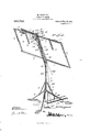
- Figure 1 is a rear perspective view of a music stand embodying the improvements of my invention
- Fig. 2 is a detail perspective View of a portion of the upper end of the device
- Fig. 3 is a rear view of this portion of the device
- Figs. 4 and 5 are detail views illustrating the movements of the leaf turning arms.
- my improved music stand may be of any desired construction, type or design, the same in the present instance embodying a standard 1 which may be constructed in telescopic or otherwise extensible sections, as best illustrated in Fig. 1, said standard being secured at its lower end to a bracket 2 to which the tripod base 3 is pivotally connected.
- the legs of the base are respectively connected to braces 4: and said braces are in turn pivotally connected to a collar 5 which is mounted to slide longitudinally on the standard 1, whereby the base may be folded up against the standard so as to economize space when the parts are partially disassembled to be stored away or carried from place to place.
- the present embodiment of the stand also includes a head-piece 6 which is detachably connected at its lower end to the upper end of the standard 1, as by a dowel and socket connection, as shown, said head-piece having pivotally connected to it upper and lower lateral projecting frame bars 7.
- These bars are mounted to swing vertically so as to lie against the head-piece 6 when the device is folded up, and the said bars are pivotally connected at their outer ends to articulated links 8 which, when extended, serve to maintain the bars 7 in properly spaced relation to each other.
- the upper bars 7 carry pivoted fingers 9 that are designed to extend down behind the musical composition so as to assist in holding it properly on the supporting frame of the stand.
- a spindle 10 is secured to and projects upwardly from the upper end of the head piece 6, and any desired number of leaf turning arms 11 are mounted to swing about said spindle as an axis, being journaled at one end thereon in any desired way and spaced by washers or similar devices.
- Each of these leaf turning arms is provided at one end with a leaf holding clip 12, the said clips being of any desired construction and being designed to engage the leaves at the upper edges of the latter so as to turn the leaves when the arms are swung around from one side of the stand to the other.
- each leaf turning arm where it is mounted on the spindle 10, is formed with two detents, designated 13 and 14, respectively.
- An actuating disk 15 is centrally journaled on a stub shaft 16 projecting rearwardly from the head-piece 6 near the upper end of the latter and said disk is provided (projecting from its forward face) with two pairs of ratchet teeth, the teeth of one pair being designated 17 and the teeth of the other pair being designated 18.
- the teeth of the last named pair project farther from the center of the disk than the teeth of the first named pair, whereby the first set of teeth will engage the 'detents of the lowermost leaf turning arm 11 (it being understood that one arm is superposed on the other) and the next set of teeth, projecting farther from the center of the disk, will then engage the teeth of the upper arm, as the disk is turned in one direction, through two successive movements, as will be hereinafter more specifically de scribed.
- the teeth 17 will successively engage the detents 13 and 14C of the lowermost leaf turning arm, said arm being first turned partially around from right to left by one of these teeth and then turned entirely around to the left by the succeeding engagement of one of the ratchet teeth 17 with the detent 14-.
- the teeth 18 will effect the swinging movement of the other leaf turning arm, so as to turn one leaf after the other.
- the disk 15 is held under tension against movement in a direction to turn the arms 11, by means of a spring 19, one end of which is secured in any desired way to the disk and the other end of which is coiled around and secured to the stub shaft 16.
- the disk is provided on its rear face with two rearwardly projecting studs, designated 22 and 23, respectively, said studs being disposed in spaced relation to each other and an actuating arm 2%. is designed to contact with said studs one after the other so as to intermittently turn the disk.
- the arm 24 is pivotally mounted on the upper end of an actuating rod 25 which is guided for a longitudinal movement along the rear side of the head-piece 6, as best illustrated in Fig.
- a contractile spring 26 is secured at one end to the rod 25 and at its other end to the head-piece 6, the spring exerting a tension on the actuating rod 25 to move it downwardly.
- the arm 24 is actuated by a spring against a nib 27 which projects from the rear side of the head-piece (5 and guides the arm in its movement, and as the rod 25 is pushed upwardly against the tension of the spring 26, the upper end of the arm will push upwardly against the stud 22 so as to impart a partial rotation of the disk 15 and effect the swinging movement of the first leaf turning arm 11, as before described.
- a nick 28 formed in the edge of the disk 15 will be brought opposite a pawl.
- the lower end of the bar is arranged for engagement by a push paw 31 pivotally connected to the upper end of a link rod -2.
- said link rod being guided by the standard 1 and movable longitrulinally along one side of the standard.
- the lower end of the link rod 32 is engaged in a socket inen'iber 33 formed on the upper end of a link 3t. and. the latter is pivotally connected to the rear end of a foot pedal suspended intermediate of its ends from a hanger 36 depending from one of the legs of the base It will thus be seen that as the forward end of the foot pedal is depressed. the rear end will push upwardly on the link 34 and link rod 32, and the pawl of the latter will push upwardly on the actuating rod 25 and impart a movement to the disk 15 in a manner previously described.
- my invention embodies, as was indicated at the outset of the specification, means for simultaneously turning the arms from left to right, back to the starting point, thus resetting the entire device.
- This mechanism embodies a resetting lever 37 which is suspended at its rear end from a hanger 38 depending from one of the legs of the base 3, said resetting lever being connected at the lower end of a cord or cable 39.
- the upper end of the cable 39 is connected in any desired way to the lower end of a rod 4% which forms part of a releasing arm, said releasing arm also including an upper section 41 which is guided for a longitudinal movement along one side of the head-piece 6 and which carries at its upper end the pawl 29 which is designed to engage the disk 15.
- the upper end of the releasing arm is secured to a flexible and preferably yielding connecting member 42 which runs through an eye 43 and which is secured to the rear end of a resetting rod 44.
- This rod is mounted on the upper end of the spindle 10 and is formed with a downwardly extending forward end 45 designed to engage both of the arms 11, whereby as the releasing arm 41 is pulled downwardly, it will positively pull upon the flexible connecting member 42 and swing the resetting rod 44 around in a direction to turn the leaf carrying arms back to the starting point.
- the first arm will engage the rod 44 and swing it around to the left, this movement being in no wise interfered with at this time, owing to the fact that the releasing arm is at the upper limit of its movement.
- the disk 15 is stopped at the proper point in its reverse movement by the engagement of a pin 46 with a pin 47 projecting from the rear face of the head-piece 6.
- the link rod 32 is also made extensible, as clearly indicated in Fig. 1, and for the same reason the cord or cable 39 is arranged to be secured to the rod 40 at two of its points in the length of the pull cord, as also clearly illustrated in said view.
- the upper bars 7 of the supporting frame are provided with spring clips 7 designed to extend down over the upper edge of the cover sheets of the musical composition so as to assist in holding it on the stand.
- a music leaf turner embodying a supporting stand, leaf turning arms mounted to swing on said stand, a ratchet disk carried by the stand and arranged to engage one arm after the other to swing it in one direction, means for imparting two successive movements to said disk so as to first swing one arm and then the other, means for automatically engaging and holding said disk sta- 1 tionary at the completion of each of said movements, means tending to turn the disk in the opposite direction, means for releasing the disk holding means from the disk, and means operable by the releasing movement of the disk holding means, for swinging said leaf turning arms in the opposite direction.
- a music leaf turner a supporting stand, leaf turning arms mounted to swing on said stand, each of said arms being formed at its pivoted end with two detents, a ratchet disk provided with a plurality of teeth designed to engage said detents in succession whereby, by two successive movements of the disk, the arms will be swung in one direction, one after the other, a pawl adapted to engage the disk at the completion of the swinging movement of each leaf turning arm, means tending to return the disk to its initial position, a resetting rod arranged to engage both arms, and an operative connection between said pawl and the resetting rod, arranged to move the latter in a direction to return the leaf carrying arms to their initial position upon the movement of the pawl in a direction to release the disk.
- a music leaf turner a supporting stand, leaf turning arms mounted to swing on said stand, a ratchet disk engaging said arms to swing them one after the other in one direction, a pawl adapted to engage said disk to hold it at the completion of its movement, means tending to return the disk to its initial position, a resetting rod in engagement with said arms and movable in a direction to return them to their initial position, a support upon which the resetting rod is pivotally mounted, and a flexible connection between the pawl and the resetting pin, for the purpose specified.
- a music leaf turner a supporting stand, leaf turning arms mounted to swing on said stand, a ratchet disk engaging said arms to swing them one after the other in one direction, a pawl adapted to engage said disk to hold it at the completion of its movement, means tending to return the disk to its initial position, a resetting rod in engage ment with said arms and movable in a direction to return them to their initial position, a support upon which the resetting rod. is pivotally mounted, and a yielding flexible connection between the pawl and the resetting pin, for the purpose specified.
- a supporting stand leaf turning arms mounted to swing on said stand, a ratchet disk arranged to engage said arms one after the other to swing them in one direction, the disk being provided with spaced studs, a reciprocating actuating arm designed to engage one stud after the other to impart two successive partial rotations to the disk, means for actuating the said reciprocating arm, and means for holding the disk stationary at the completion of each movement.
- a music leaf turner embodying a sup porting stand, leaf turning arms mounted to swing on said stand, a ratchet disk operatively connected to said arms to swing them in one direction one after the other, the disk being formed with spaced studs, a spring pressed actuating arm designed to engage said studs one after the other, means for holding the disk stationary after each of its movements, an actuating rod carrying said spring pressed actuating arm, a push pawl engaging said rod to move the same in one direction, means tending to return the leaf turning arms, that is, to move them in the opposite direction, and pedal actuated devices operatively connected to said push pawl.
Landscapes
- Toys (AREA)
Description
M.. VINEYARD.
MUSIC LEAF TURNER.
APPLICATION FILED 111N228, 1910.
2 SHEETS-SHEET 1.
Patented May 30, 1911.
M. VINEYARD.
MUSIC LEAF TURNER,
APPLICATION FILED JUNE 28, 1910.
2 SHEETSSHEET 2.
Patented May 30, 1911.
UNITED STATES PATENT OFFICE.
MANTLE VINEYARD, OF MISSOULA, MONTANA.
MUSIC-LEAF TURNER.
To all whom it may concern:
Be it known that I, MANTLE VINEYARD, citizen of the United States, residing at Missoula, in the county of Missoula and State of Montana, have invented certain new and useful Improvements in Music-Leaf Turners, of which the following is a specification.
This invention comprehends certain new and useful improvements in apparatus for turning the leaves of music or other books, or sheet music, and the invention has for its primary object an improved construction of music leaf turner which will enable the performer to easily turn the leaves of the musical composition being played, without the necessity of using either hand for such operation, and hence without the necessity of even momentarily stopping the rendition of the music.
The invention has for a further object a simple, durable and efficient construction of apparatus of this character embodying improved pedal actuated operating mechanisms, one of said mechanisms being arranged to turn the leaves in one direction one after the other, as required, and the other of said mechanisms being arranged to simultaneously turn the leaves in the opposite direction back to the starting point, either for the purpose of closing up the sheet music or'book preparatory to removing it from the stand or for the purpose of again playing the selection.
With these and other objects in view as will more fully appear as the description proceeds, the invention consists in certain constructions, arrangements and cornbinations of the parts that I shall hereinafter fully describe and claim.
For a full understanding of the invention, reference is to be had to the following description and accompanying drawings, in which:
Figure 1 is a rear perspective view of a music stand embodying the improvements of my invention; Fig. 2 is a detail perspective View of a portion of the upper end of the device; Fig. 3 is a rear view of this portion of the device; and Figs. 4 and 5 are detail views illustrating the movements of the leaf turning arms.
Corresponding and like parts are referred to in the following description and indicated in all the views of the drawings by the same reference characters.
Specification of Letters Patent.
Application filed June 28, 1910.
Patented May 30, 1911. Serial No. 569,391.
So far as its supporting functions are con cerned, my improved music stand may be of any desired construction, type or design, the same in the present instance embodying a standard 1 which may be constructed in telescopic or otherwise extensible sections, as best illustrated in Fig. 1, said standard being secured at its lower end to a bracket 2 to which the tripod base 3 is pivotally connected. The legs of the base are respectively connected to braces 4: and said braces are in turn pivotally connected to a collar 5 which is mounted to slide longitudinally on the standard 1, whereby the base may be folded up against the standard so as to economize space when the parts are partially disassembled to be stored away or carried from place to place.
The present embodiment of the stand also includes a head-piece 6 which is detachably connected at its lower end to the upper end of the standard 1, as by a dowel and socket connection, as shown, said head-piece having pivotally connected to it upper and lower lateral projecting frame bars 7. These bars are mounted to swing vertically so as to lie against the head-piece 6 when the device is folded up, and the said bars are pivotally connected at their outer ends to articulated links 8 which, when extended, serve to maintain the bars 7 in properly spaced relation to each other. The upper bars 7 carry pivoted fingers 9 that are designed to extend down behind the musical composition so as to assist in holding it properly on the supporting frame of the stand.
A spindle 10 is secured to and projects upwardly from the upper end of the head piece 6, and any desired number of leaf turning arms 11 are mounted to swing about said spindle as an axis, being journaled at one end thereon in any desired way and spaced by washers or similar devices. Each of these leaf turning arms is provided at one end with a leaf holding clip 12, the said clips being of any desired construction and being designed to engage the leaves at the upper edges of the latter so as to turn the leaves when the arms are swung around from one side of the stand to the other.
The inner end of each leaf turning arm, where it is mounted on the spindle 10, is formed with two detents, designated 13 and 14, respectively. An actuating disk 15 is centrally journaled on a stub shaft 16 projecting rearwardly from the head-piece 6 near the upper end of the latter and said disk is provided (projecting from its forward face) with two pairs of ratchet teeth, the teeth of one pair being designated 17 and the teeth of the other pair being designated 18. The teeth of the last named pair project farther from the center of the disk than the teeth of the first named pair, whereby the first set of teeth will engage the 'detents of the lowermost leaf turning arm 11 (it being understood that one arm is superposed on the other) and the next set of teeth, projecting farther from the center of the disk, will then engage the teeth of the upper arm, as the disk is turned in one direction, through two successive movements, as will be hereinafter more specifically de scribed. In the movements of the disk 15, the teeth 17 will successively engage the detents 13 and 14C of the lowermost leaf turning arm, said arm being first turned partially around from right to left by one of these teeth and then turned entirely around to the left by the succeeding engagement of one of the ratchet teeth 17 with the detent 14-. Correspondingly, as above noted, the teeth 18 will effect the swinging movement of the other leaf turning arm, so as to turn one leaf after the other.
The disk 15 is held under tension against movement in a direction to turn the arms 11, by means of a spring 19, one end of which is secured in any desired way to the disk and the other end of which is coiled around and secured to the stub shaft 16. In order to turn the disk 15 against the tensioning device which holds it, the disk is provided on its rear face with two rearwardly projecting studs, designated 22 and 23, respectively, said studs being disposed in spaced relation to each other and an actuating arm 2%. is designed to contact with said studs one after the other so as to intermittently turn the disk. The arm 24 is pivotally mounted on the upper end of an actuating rod 25 which is guided for a longitudinal movement along the rear side of the head-piece 6, as best illustrated in Fig. 1, and a contractile spring 26 is secured at one end to the rod 25 and at its other end to the head-piece 6, the spring exerting a tension on the actuating rod 25 to move it downwardly. The arm 24: is actuated by a spring against a nib 27 which projects from the rear side of the head-piece (5 and guides the arm in its movement, and as the rod 25 is pushed upwardly against the tension of the spring 26, the upper end of the arm will push upwardly against the stud 22 so as to impart a partial rotation of the disk 15 and effect the swinging movement of the first leaf turning arm 11, as before described. At the completion of this first movement a nick 28 formed in the edge of the disk 15 will be brought opposite a pawl. 29 and the pawl will thereupon engage the disk and prevent the reverse movement of the latter. At the same time, the neXt pin or stud of the disk 15 will be brought down to a point where the next succeeding upward movement of the arm 24 will engage it and consequently said succeeding movement of the arm 24 will impart a second partial rotation to the disk 15 and effect the turning of the other arm 11. At the completion of this last named movement the pawl '29 will engage a notch 30 that is formed in the edge of the disk 15 in spaced relation to the notch or nick 28. Thus the leaves will be turned one after the other. In order to move the actuating bar 25 upwardly for the purpose described, the lower end of the bar is arranged for engagement by a push paw 31 pivotally connected to the upper end of a link rod -2. said link rod being guided by the standard 1 and movable longitrulinally along one side of the standard. The lower end of the link rod 32 is engaged in a socket inen'iber 33 formed on the upper end of a link 3t. and. the latter is pivotally connected to the rear end of a foot pedal suspended intermediate of its ends from a hanger 36 depending from one of the legs of the base It will thus be seen that as the forward end of the foot pedal is depressed. the rear end will push upwardly on the link 34 and link rod 32, and the pawl of the latter will push upwardly on the actuating rod 25 and impart a movement to the disk 15 in a manner previously described.
In addition to the means for turning the leaves from right to left, one after the other, my invention embodies, as was indicated at the outset of the specification, means for simultaneously turning the arms from left to right, back to the starting point, thus resetting the entire device. This mechanism embodies a resetting lever 37 which is suspended at its rear end from a hanger 38 depending from one of the legs of the base 3, said resetting lever being connected at the lower end of a cord or cable 39. The upper end of the cable 39 is connected in any desired way to the lower end of a rod 4% which forms part of a releasing arm, said releasing arm also including an upper section 41 which is guided for a longitudinal movement along one side of the head-piece 6 and which carries at its upper end the pawl 29 which is designed to engage the disk 15. Hence it will be understood that as the resetting lever 37 is depressed, the consequent downward movement of the cord or cable 39 and the releasing arm formed by the sections 4-0 and 11 will effect the release of the pawl 29 from the disk 15 and allow the latter to be returned to its full extent under the influence of the spring 19. In order to return, at the same time, the leaf turning arms, the upper end of the releasing arm is secured to a flexible and preferably yielding connecting member 42 which runs through an eye 43 and which is secured to the rear end of a resetting rod 44. This rod is mounted on the upper end of the spindle 10 and is formed with a downwardly extending forward end 45 designed to engage both of the arms 11, whereby as the releasing arm 41 is pulled downwardly, it will positively pull upon the flexible connecting member 42 and swing the resetting rod 44 around in a direction to turn the leaf carrying arms back to the starting point. Obviously, in the movement of the arms 11 from right to left, the first arm will engage the rod 44 and swing it around to the left, this movement being in no wise interfered with at this time, owing to the fact that the releasing arm is at the upper limit of its movement. The disk 15 is stopped at the proper point in its reverse movement by the engagement of a pin 46 with a pin 47 projecting from the rear face of the head-piece 6.
As the standard 1 is extensible, the link rod 32 is also made extensible, as clearly indicated in Fig. 1, and for the same reason the cord or cable 39 is arranged to be secured to the rod 40 at two of its points in the length of the pull cord, as also clearly illustrated in said view.
The detail operations, movements and functions of the different parts of my improved music stand and leaf turning apparatus, have been described in connection with the construction and arrangements of the parts, and I therefore deem it only necessary to now generally describe the operation.
When a piece of music is placed on the frame of the stand, its leaves are engaged by the clips 12 of the leaf turning arms 11, said arms being, of course, swung around to the right. When it is desired to turn one of the leaves, it is only necessary for the performer to press downwardly upon the pedal 35, whereupon the arm 24 will be pushed upwardly against the stud 22 and effect a partial rotation of the disk 15. This first movement of the disk will cause the ratchet teeth 17 to engage the detents 13 and 14 respectively, of the lowermost leaf turning arm, and the first leaf will thus be turned over, the disk 15 being caught at the completion of such movement by the pawl 29. When it is necessary to turn over the next leaf of the musical composition, a succeeding downward movement of the pedal 35 will complete the turning movement of the disk 15 in the same direction, the arm 24 engaging the stud 23 in this completed movement and causing the teeth 18 of the disk to engage in succession the detents 13 and 14 of the next turning arm so as to swing the latter from right to left. In order to restore the parts to their initial position, it is only necessary for the erformer to depress the resetting lever 3'f whereupon the pawl 29 will be released from the disk 15, the disk will be permitted to rotate rearwardly and at the same time the downward movement of the releasing arm which is formed by the rod 40 and section 41, will draw upon the flexible connecting member 42 and swing the'resetting rod 43 around to return the leaf turning arms.
Preferably, the upper bars 7 of the supporting frame are provided with spring clips 7 designed to extend down over the upper edge of the cover sheets of the musical composition so as to assist in holding it on the stand.
Having thus described the invention, what is claimed as new is:
1. A music leaf turner, embodying a supporting stand, leaf turning arms mounted to swing on said stand, a ratchet disk carried by the stand and arranged to engage one arm after the other to swing it in one direction, means for imparting two successive movements to said disk so as to first swing one arm and then the other, means for automatically engaging and holding said disk sta- 1 tionary at the completion of each of said movements, means tending to turn the disk in the opposite direction, means for releasing the disk holding means from the disk, and means operable by the releasing movement of the disk holding means, for swinging said leaf turning arms in the opposite direction.
2. In a music leaf turner, a supporting stand, leaf turning arms mounted to swing on said stand, each of said arms being formed at its pivoted end with two detents, a ratchet disk provided with a plurality of teeth designed to engage said detents in succession whereby, by two successive movements of the disk, the arms will be swung in one direction, one after the other, a pawl adapted to engage the disk at the completion of the swinging movement of each leaf turning arm, means tending to return the disk to its initial position, a resetting rod arranged to engage both arms, and an operative connection between said pawl and the resetting rod, arranged to move the latter in a direction to return the leaf carrying arms to their initial position upon the movement of the pawl in a direction to release the disk.
3. In a music leaf turner, a supporting stand, leaf turning arms mounted to swing on said stand, a ratchet disk engaging said arms to swing them one after the other in one direction, a pawl adapted to engage said disk to hold it at the completion of its movement, means tending to return the disk to its initial position, a resetting rod in engagement with said arms and movable in a direction to return them to their initial position, a support upon which the resetting rod is pivotally mounted, and a flexible connection between the pawl and the resetting pin, for the purpose specified.
4. In a music leaf turner, a supporting stand, leaf turning arms mounted to swing on said stand, a ratchet disk engaging said arms to swing them one after the other in one direction, a pawl adapted to engage said disk to hold it at the completion of its movement, means tending to return the disk to its initial position, a resetting rod in engage ment with said arms and movable in a direction to return them to their initial position, a support upon which the resetting rod. is pivotally mounted, and a yielding flexible connection between the pawl and the resetting pin, for the purpose specified.
5. In a music leaf turner, a supporting stand, leaf turning arms mounted to swing on said stand, a ratchet disk arranged to engage said arms one after the other to swing them in one direction, the disk being provided with spaced studs, a reciprocating actuating arm designed to engage one stud after the other to impart two successive partial rotations to the disk, means for actuating the said reciprocating arm, and means for holding the disk stationary at the completion of each movement.
6. A music leaf turner, embodying a sup porting stand, leaf turning arms mounted to swing on said stand, a ratchet disk operatively connected to said arms to swing them in one direction one after the other, the disk being formed with spaced studs, a spring pressed actuating arm designed to engage said studs one after the other, means for holding the disk stationary after each of its movements, an actuating rod carrying said spring pressed actuating arm, a push pawl engaging said rod to move the same in one direction, means tending to return the leaf turning arms, that is, to move them in the opposite direction, and pedal actuated devices operatively connected to said push pawl.
In testimony whereof I aflix my signature in presence of two witnesses.
EDWARD G. MULRoNnY, Gno. F. ULLRIGH.
Copies of this patent may be obtained for five cents each, by addressing the Commissioner of Patents, Washington, D. C.
Priority Applications (1)
| Application Number | Priority Date | Filing Date | Title |
|---|---|---|---|
| US56939110A US993740A (en) | 1910-06-28 | 1910-06-28 | Music-leaf turner. |
Applications Claiming Priority (1)
| Application Number | Priority Date | Filing Date | Title |
|---|---|---|---|
| US56939110A US993740A (en) | 1910-06-28 | 1910-06-28 | Music-leaf turner. |
Publications (1)
| Publication Number | Publication Date |
|---|---|
| US993740A true US993740A (en) | 1911-05-30 |
Family
ID=3062073
Family Applications (1)
| Application Number | Title | Priority Date | Filing Date |
|---|---|---|---|
| US56939110A Expired - Lifetime US993740A (en) | 1910-06-28 | 1910-06-28 | Music-leaf turner. |
Country Status (1)
| Country | Link |
|---|---|
| US (1) | US993740A (en) |
-
1910
- 1910-06-28 US US56939110A patent/US993740A/en not_active Expired - Lifetime
Similar Documents
| Publication | Publication Date | Title |
|---|---|---|
| US993740A (en) | Music-leaf turner. | |
| US1046628A (en) | Leaf-turner. | |
| US876781A (en) | Music-leaf turner. | |
| US604825A (en) | Thirds to arthur f | |
| US411052A (en) | Music-leaf turner | |
| US1944295A (en) | Music leaf-turning machine | |
| US1914070A (en) | Music sheet turner | |
| US997839A (en) | Music-leaf turner. | |
| US1008671A (en) | Music-stand and leaf-turning apparatus. | |
| US1270114A (en) | Music-turner. | |
| US537733A (en) | Leaf-turner | |
| US475317A (en) | Music-leaf turner | |
| US919978A (en) | Music-leaf turner. | |
| US792304A (en) | Combined music rack and turner. | |
| US966055A (en) | Music-leaf turner. | |
| US781055A (en) | Music-leaf turner. | |
| US1452804A (en) | Device for turning music | |
| US799959A (en) | Combined music rack and turner. | |
| US1353582A (en) | Music-leaf turner | |
| US592021A (en) | bobbins | |
| US707671A (en) | Music-leaf turner. | |
| US973831A (en) | Music-leaf turner. | |
| US818404A (en) | Music-leaf-turning stand. | |
| US1131125A (en) | Music-leaf turner. | |
| US957370A (en) | Sheet-music turner. |