US9934935B2 - Multi charged particle beam writing apparatus and multi charged particle beam writing method - Google Patents
Multi charged particle beam writing apparatus and multi charged particle beam writing method Download PDFInfo
- Publication number
- US9934935B2 US9934935B2 US15/225,969 US201615225969A US9934935B2 US 9934935 B2 US9934935 B2 US 9934935B2 US 201615225969 A US201615225969 A US 201615225969A US 9934935 B2 US9934935 B2 US 9934935B2
- Authority
- US
- United States
- Prior art keywords
- writing
- shot
- time
- irradiation time
- beams
- Prior art date
- Legal status (The legal status is an assumption and is not a legal conclusion. Google has not performed a legal analysis and makes no representation as to the accuracy of the status listed.)
- Active
Links
- 239000002245 particle Substances 0.000 title claims abstract description 24
- 238000000034 method Methods 0.000 title claims description 41
- 238000004364 calculation method Methods 0.000 claims abstract description 121
- 238000012545 processing Methods 0.000 claims abstract description 92
- 230000007246 mechanism Effects 0.000 claims description 45
- 230000000694 effects Effects 0.000 description 34
- 239000000758 substrate Substances 0.000 description 34
- 238000012937 correction Methods 0.000 description 27
- 238000004904 shortening Methods 0.000 description 23
- 238000010894 electron beam technology Methods 0.000 description 21
- 230000006870 function Effects 0.000 description 19
- 238000010586 diagram Methods 0.000 description 16
- 230000005540 biological transmission Effects 0.000 description 15
- 239000011295 pitch Substances 0.000 description 15
- 230000001678 irradiating effect Effects 0.000 description 12
- 239000004065 semiconductor Substances 0.000 description 9
- 238000003860 storage Methods 0.000 description 8
- 230000009467 reduction Effects 0.000 description 7
- 101000957815 Culex pipiens Alpha-glucosidase Proteins 0.000 description 5
- 238000013139 quantization Methods 0.000 description 5
- 230000007704 transition Effects 0.000 description 5
- 230000003287 optical effect Effects 0.000 description 4
- 230000001360 synchronised effect Effects 0.000 description 4
- 238000009434 installation Methods 0.000 description 3
- 230000008901 benefit Effects 0.000 description 2
- 230000008859 change Effects 0.000 description 2
- 238000005286 illumination Methods 0.000 description 2
- 238000004519 manufacturing process Methods 0.000 description 2
- 230000004048 modification Effects 0.000 description 2
- 238000012986 modification Methods 0.000 description 2
- 230000008569 process Effects 0.000 description 2
- 230000004044 response Effects 0.000 description 2
- XUIMIQQOPSSXEZ-UHFFFAOYSA-N Silicon Chemical compound [Si] XUIMIQQOPSSXEZ-UHFFFAOYSA-N 0.000 description 1
- 230000001133 acceleration Effects 0.000 description 1
- 238000005520 cutting process Methods 0.000 description 1
- 238000011161 development Methods 0.000 description 1
- 230000010354 integration Effects 0.000 description 1
- 238000010884 ion-beam technique Methods 0.000 description 1
- 238000001459 lithography Methods 0.000 description 1
- 239000011159 matrix material Substances 0.000 description 1
- 231100000628 reference dose Toxicity 0.000 description 1
- 229910052710 silicon Inorganic materials 0.000 description 1
- 239000010703 silicon Substances 0.000 description 1
- 230000006641 stabilisation Effects 0.000 description 1
- 238000011105 stabilization Methods 0.000 description 1
Images


Classifications
-
- G—PHYSICS
- G03—PHOTOGRAPHY; CINEMATOGRAPHY; ANALOGOUS TECHNIQUES USING WAVES OTHER THAN OPTICAL WAVES; ELECTROGRAPHY; HOLOGRAPHY
- G03F—PHOTOMECHANICAL PRODUCTION OF TEXTURED OR PATTERNED SURFACES, e.g. FOR PRINTING, FOR PROCESSING OF SEMICONDUCTOR DEVICES; MATERIALS THEREFOR; ORIGINALS THEREFOR; APPARATUS SPECIALLY ADAPTED THEREFOR
- G03F1/00—Originals for photomechanical production of textured or patterned surfaces, e.g., masks, photo-masks, reticles; Mask blanks or pellicles therefor; Containers specially adapted therefor; Preparation thereof
- G03F1/20—Masks or mask blanks for imaging by charged particle beam [CPB] radiation, e.g. by electron beam; Preparation thereof
-
- H—ELECTRICITY
- H01—ELECTRIC ELEMENTS
- H01J—ELECTRIC DISCHARGE TUBES OR DISCHARGE LAMPS
- H01J37/00—Discharge tubes with provision for introducing objects or material to be exposed to the discharge, e.g. for the purpose of examination or processing thereof
- H01J37/02—Details
- H01J37/20—Means for supporting or positioning the object or the material; Means for adjusting diaphragms or lenses associated with the support
-
- G—PHYSICS
- G03—PHOTOGRAPHY; CINEMATOGRAPHY; ANALOGOUS TECHNIQUES USING WAVES OTHER THAN OPTICAL WAVES; ELECTROGRAPHY; HOLOGRAPHY
- G03F—PHOTOMECHANICAL PRODUCTION OF TEXTURED OR PATTERNED SURFACES, e.g. FOR PRINTING, FOR PROCESSING OF SEMICONDUCTOR DEVICES; MATERIALS THEREFOR; ORIGINALS THEREFOR; APPARATUS SPECIALLY ADAPTED THEREFOR
- G03F1/00—Originals for photomechanical production of textured or patterned surfaces, e.g., masks, photo-masks, reticles; Mask blanks or pellicles therefor; Containers specially adapted therefor; Preparation thereof
- G03F1/68—Preparation processes not covered by groups G03F1/20 - G03F1/50
- G03F1/76—Patterning of masks by imaging
- G03F1/78—Patterning of masks by imaging by charged particle beam [CPB], e.g. electron beam patterning of masks
-
- G—PHYSICS
- G03—PHOTOGRAPHY; CINEMATOGRAPHY; ANALOGOUS TECHNIQUES USING WAVES OTHER THAN OPTICAL WAVES; ELECTROGRAPHY; HOLOGRAPHY
- G03F—PHOTOMECHANICAL PRODUCTION OF TEXTURED OR PATTERNED SURFACES, e.g. FOR PRINTING, FOR PROCESSING OF SEMICONDUCTOR DEVICES; MATERIALS THEREFOR; ORIGINALS THEREFOR; APPARATUS SPECIALLY ADAPTED THEREFOR
- G03F7/00—Photomechanical, e.g. photolithographic, production of textured or patterned surfaces, e.g. printing surfaces; Materials therefor, e.g. comprising photoresists; Apparatus specially adapted therefor
- G03F7/70—Microphotolithographic exposure; Apparatus therefor
- G03F7/70425—Imaging strategies, e.g. for increasing throughput or resolution, printing product fields larger than the image field or compensating lithography- or non-lithography errors, e.g. proximity correction, mix-and-match, stitching or double patterning
- G03F7/7045—Hybrid exposures, i.e. multiple exposures of the same area using different types of exposure apparatus, e.g. combining projection, proximity, direct write, interferometric, UV, x-ray or particle beam
-
- G—PHYSICS
- G03—PHOTOGRAPHY; CINEMATOGRAPHY; ANALOGOUS TECHNIQUES USING WAVES OTHER THAN OPTICAL WAVES; ELECTROGRAPHY; HOLOGRAPHY
- G03F—PHOTOMECHANICAL PRODUCTION OF TEXTURED OR PATTERNED SURFACES, e.g. FOR PRINTING, FOR PROCESSING OF SEMICONDUCTOR DEVICES; MATERIALS THEREFOR; ORIGINALS THEREFOR; APPARATUS SPECIALLY ADAPTED THEREFOR
- G03F7/00—Photomechanical, e.g. photolithographic, production of textured or patterned surfaces, e.g. printing surfaces; Materials therefor, e.g. comprising photoresists; Apparatus specially adapted therefor
- G03F7/70—Microphotolithographic exposure; Apparatus therefor
- G03F7/70691—Handling of masks or workpieces
- G03F7/70716—Stages
-
- G—PHYSICS
- G03—PHOTOGRAPHY; CINEMATOGRAPHY; ANALOGOUS TECHNIQUES USING WAVES OTHER THAN OPTICAL WAVES; ELECTROGRAPHY; HOLOGRAPHY
- G03F—PHOTOMECHANICAL PRODUCTION OF TEXTURED OR PATTERNED SURFACES, e.g. FOR PRINTING, FOR PROCESSING OF SEMICONDUCTOR DEVICES; MATERIALS THEREFOR; ORIGINALS THEREFOR; APPARATUS SPECIALLY ADAPTED THEREFOR
- G03F7/00—Photomechanical, e.g. photolithographic, production of textured or patterned surfaces, e.g. printing surfaces; Materials therefor, e.g. comprising photoresists; Apparatus specially adapted therefor
- G03F7/70—Microphotolithographic exposure; Apparatus therefor
- G03F7/70691—Handling of masks or workpieces
- G03F7/70766—Reaction force control means, e.g. countermass
-
- H—ELECTRICITY
- H01—ELECTRIC ELEMENTS
- H01J—ELECTRIC DISCHARGE TUBES OR DISCHARGE LAMPS
- H01J37/00—Discharge tubes with provision for introducing objects or material to be exposed to the discharge, e.g. for the purpose of examination or processing thereof
- H01J37/02—Details
- H01J37/04—Arrangements of electrodes and associated parts for generating or controlling the discharge, e.g. electron-optical arrangement or ion-optical arrangement
- H01J37/045—Beam blanking or chopping, i.e. arrangements for momentarily interrupting exposure to the discharge
-
- H—ELECTRICITY
- H01—ELECTRIC ELEMENTS
- H01J—ELECTRIC DISCHARGE TUBES OR DISCHARGE LAMPS
- H01J37/00—Discharge tubes with provision for introducing objects or material to be exposed to the discharge, e.g. for the purpose of examination or processing thereof
- H01J37/02—Details
- H01J37/24—Circuit arrangements not adapted to a particular application of the tube and not otherwise provided for
- H01J37/243—Beam current control or regulation circuits
-
- H—ELECTRICITY
- H01—ELECTRIC ELEMENTS
- H01J—ELECTRIC DISCHARGE TUBES OR DISCHARGE LAMPS
- H01J37/00—Discharge tubes with provision for introducing objects or material to be exposed to the discharge, e.g. for the purpose of examination or processing thereof
- H01J37/30—Electron-beam or ion-beam tubes for localised treatment of objects
- H01J37/302—Controlling tubes by external information, e.g. programme control
- H01J37/3023—Programme control
- H01J37/3026—Patterning strategy
-
- H—ELECTRICITY
- H01—ELECTRIC ELEMENTS
- H01J—ELECTRIC DISCHARGE TUBES OR DISCHARGE LAMPS
- H01J37/00—Discharge tubes with provision for introducing objects or material to be exposed to the discharge, e.g. for the purpose of examination or processing thereof
- H01J37/30—Electron-beam or ion-beam tubes for localised treatment of objects
- H01J37/317—Electron-beam or ion-beam tubes for localised treatment of objects for changing properties of the objects or for applying thin layers thereon, e.g. for ion implantation
- H01J37/3174—Particle-beam lithography, e.g. electron beam lithography
- H01J37/3177—Multi-beam, e.g. fly's eye, comb probe
-
- H—ELECTRICITY
- H01—ELECTRIC ELEMENTS
- H01J—ELECTRIC DISCHARGE TUBES OR DISCHARGE LAMPS
- H01J2237/00—Discharge tubes exposing object to beam, e.g. for analysis treatment, etching, imaging
- H01J2237/04—Means for controlling the discharge
- H01J2237/043—Beam blanking
- H01J2237/0435—Multi-aperture
-
- H—ELECTRICITY
- H01—ELECTRIC ELEMENTS
- H01J—ELECTRIC DISCHARGE TUBES OR DISCHARGE LAMPS
- H01J2237/00—Discharge tubes exposing object to beam, e.g. for analysis treatment, etching, imaging
- H01J2237/04—Means for controlling the discharge
- H01J2237/045—Diaphragms
- H01J2237/0451—Diaphragms with fixed aperture
- H01J2237/0453—Diaphragms with fixed aperture multiple apertures
-
- H—ELECTRICITY
- H01—ELECTRIC ELEMENTS
- H01J—ELECTRIC DISCHARGE TUBES OR DISCHARGE LAMPS
- H01J2237/00—Discharge tubes exposing object to beam, e.g. for analysis treatment, etching, imaging
- H01J2237/20—Positioning, supporting, modifying or maintaining the physical state of objects being observed or treated
- H01J2237/202—Movement
- H01J2237/20278—Motorised movement
- H01J2237/20285—Motorised movement computer-controlled
-
- H—ELECTRICITY
- H01—ELECTRIC ELEMENTS
- H01J—ELECTRIC DISCHARGE TUBES OR DISCHARGE LAMPS
- H01J2237/00—Discharge tubes exposing object to beam, e.g. for analysis treatment, etching, imaging
- H01J2237/20—Positioning, supporting, modifying or maintaining the physical state of objects being observed or treated
- H01J2237/202—Movement
- H01J2237/20292—Means for position and/or orientation registration
-
- H—ELECTRICITY
- H01—ELECTRIC ELEMENTS
- H01J—ELECTRIC DISCHARGE TUBES OR DISCHARGE LAMPS
- H01J2237/00—Discharge tubes exposing object to beam, e.g. for analysis treatment, etching, imaging
- H01J2237/30—Electron or ion beam tubes for processing objects
- H01J2237/304—Controlling tubes
- H01J2237/30405—Details
- H01J2237/30416—Handling of data
- H01J2237/30422—Data compression
-
- H—ELECTRICITY
- H01—ELECTRIC ELEMENTS
- H01J—ELECTRIC DISCHARGE TUBES OR DISCHARGE LAMPS
- H01J2237/00—Discharge tubes exposing object to beam, e.g. for analysis treatment, etching, imaging
- H01J2237/30—Electron or ion beam tubes for processing objects
- H01J2237/304—Controlling tubes
- H01J2237/30433—System calibration
- H01J2237/30438—Registration
-
- H—ELECTRICITY
- H01—ELECTRIC ELEMENTS
- H01J—ELECTRIC DISCHARGE TUBES OR DISCHARGE LAMPS
- H01J2237/00—Discharge tubes exposing object to beam, e.g. for analysis treatment, etching, imaging
- H01J2237/30—Electron or ion beam tubes for processing objects
- H01J2237/317—Processing objects on a microscale
- H01J2237/3175—Lithography
- H01J2237/31761—Patterning strategy
- H01J2237/31762—Computer and memory organisation
-
- H—ELECTRICITY
- H01—ELECTRIC ELEMENTS
- H01J—ELECTRIC DISCHARGE TUBES OR DISCHARGE LAMPS
- H01J2237/00—Discharge tubes exposing object to beam, e.g. for analysis treatment, etching, imaging
- H01J2237/30—Electron or ion beam tubes for processing objects
- H01J2237/317—Processing objects on a microscale
- H01J2237/3175—Lithography
- H01J2237/31761—Patterning strategy
- H01J2237/31764—Dividing into sub-patterns
Definitions
- Embodiments of the present invention relate generally to a multi charged particle beam writing apparatus and a multi charged particle beam writing method, and more specifically, relate, for example, to a control method of the stage used in multi-beam writing.
- the lithography technique that advances miniaturization of semiconductor devices is extremely important as a unique process whereby patterns are formed in semiconductor manufacturing.
- the line width (critical dimension) required for semiconductor device circuits becomes progressively narrower year by year.
- the electron beam writing technique which intrinsically has excellent resolution, is used for writing or “drawing” patterns on a wafer and the like with electron beams.
- a writing apparatus employing the multi-beam technique forms multi-beams by letting portions of an electron beam emitted from an electron gun pass through a corresponding hole of a plurality of holes in a mask, performs blanking control for each beam, reduces each unblocked beam by an optical system, and deflects it by a deflector so as to irradiate a desired position on a target object or “sample”.
- the multi-beam writing apparatus employs a method, which is currently under development, of irradiating multi-beams to a plurality of corresponding pixel regions at a time while moving a stage at a constant speed on the basis of a raster scanning system.
- the stage speed is controlled at a constant speed, it may decrease due to turning of the stage at starting or finishing writing a stripe region.
- beam on/off control is performed with a fixed shot cycle, the dose becomes excessive due to the stage speed decrease generated at the stage turning.
- dose adjustment for preventing such excess of the dose there is disclosed a method of cutting a superfluous dose by a blanking mechanism (for example, refer to Japanese Unexamined Publication No. JP 2009-532887A).
- a blanking mechanism for example, refer to Japanese Unexamined Publication No. JP 2009-532887A.
- proximity effect correction by dose correction needs to be performed.
- the irradiation time needs to be set long in the region with low pattern density, and to be set short in the region with high pattern density.
- the stage speed is controlled at a constant speed similarly to the conventional raster scanning system, the speed is determined according to the beam whose irradiation time is longest. Therefore, the stage speed is determined according to the region where the irradiation time is long and the pattern density is low.
- the region where the pattern density is low writing takes time because the irradiation time is long from the first, and further, if there is a region with no pattern while the stage is moving, latency exists in which merely waiting is performed without irradiating beams. Therefore, in the region with low pattern density, there may occur an inversion phenomenon in that the throughput is lower than that of the single beam writing method of a vector system.
- high throughput performance in the region with high pattern density cancels out the throughput decrease caused by the inversion phenomenon, and increases the total throughput higher than that of the single beam writing method.
- stage speed is determined according to the region where irradiation time is long and pattern density is low, latency to wait for a next shot occurs, even when beam irradiation has been completed, in the region where pattern density is high.
- inherent high throughput performance of the multi-beam writing method has not been fully achieved.
- a multi charged particle beam writing apparatus includes a writing mechanism configured to include a stage, being movable, for mounting a target object serving as a writing target thereon, and to write a pattern on the target object with multi-beams of a charged particle beam, a maximum irradiation time acquisition processing circuitry configured to acquire, for each shot of the multi-beams, a maximum irradiation time of irradiation time of each beam of the multi-beams, a unit region writing time calculation processing circuitry configured to calculate, using the maximum irradiation time for the each shot, a unit region writing time by totalizing the maximum irradiation time of the each shot of a plurality of times of shots of the multi-beams which irradiate a unit region concerned while the stage is moved, for each unit region of a plurality of unit regions obtained by dividing a writing region of the target object, a stage speed calculation processing circuitry configured to calculate a speed of the stage for the each unit
- a multi charged particle beam writing method includes acquiring, for each shot of multi-beams of a charged particle beam, a maximum irradiation time of irradiation time of each beam of the multi-beams; calculating, using the maximum irradiation time for the each shot, a unit region writing time by totalizing the maximum irradiation time of the each shot of a plurality of times of shots of the multi-beams to irradiate a unit region concerned while moving a stage on which a target object is placed, for each unit region of a plurality of unit regions obtained by dividing a writing region of the target object to be written; calculating a speed of the stage for the each unit region by using the unit region writing time so that the speed of the stage becomes variable; and writing a pattern on the target object with the multi-beams of the charged particle beam while variably controlling the speed of the stage.
- a multi charged particle beam writing method includes writing a pattern on a target object with multi-beams of a charged particle beam while variably controlling a speed of a stage, such that the speed of the stage on which the target object is placed is controlled at high speed when writing a region on the target object of high pattern density of the pattern to be written, and such that the speed of the stage is controlled at low speed when writing a region on the target object of low pattern density.
- FIG. 1 is a schematic diagram showing a configuration of a writing apparatus according to a first embodiment
- FIG. 2 is a conceptual diagram showing a configuration of a forming aperture array substrate according to the first embodiment
- FIG. 3 is a top view conceptual diagram showing a part of a blanking aperture array mechanism according to the first embodiment
- FIG. 4 is a conceptual diagram explaining an example of a writing operation according to the first embodiment
- FIG. 5 shows an example of an irradiation region of multi-beams and a pixel to be written according to the first embodiment
- FIG. 6 shows an example illustrating a writing method of multi-beams according to the first embodiment
- FIG. 7 is a flowchart showing main steps of a writing method according to the first embodiment
- FIGS. 8A and 8B show examples illustrating processing for shortening a maximum irradiation time according to the first embodiment
- FIGS. 9A to 9F show examples of the relation between the stage speed and other factors according to the first embodiment
- FIGS. 10A and 10B show the relation between shot time shortening and a pattern density according to the first embodiment
- FIG. 11 is a conceptual diagram showing the configuration of a writing apparatus according to a second embodiment
- FIG. 12 is a schematic diagram showing the internal configuration of an individual blanking control circuit and a common blanking control circuit according to the second embodiment
- FIG. 13 is a flowchart showing main steps of a writing method according to the second embodiment
- FIGS. 15A and 15B show examples illustrating processing for shortening a maximum irradiation time according to the second embodiment
- FIG. 16 shows an example of a part of irradiation time array data according to the second embodiment
- FIG. 17 is a timing chart showing a beam on/off switching operation with respect to a part of an irradiation step during one shot according to the second embodiment
- FIG. 18 is a conceptual diagram describing a blanking operation according to the second embodiment.
- FIG. 19 is a conceptual diagram showing the configuration of a writing apparatus according to a third embodiment.
- FIG. 20 is a flowchart showing main steps of a writing method according to the third embodiment.
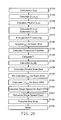
- FIG. 21 shows an example of a frequency function graph according to the third embodiment
- FIG. 22 shows another example of the frequency function graph according to the third embodiment.
- FIGS. 23A to 23C show examples illustrating processing for shortening a maximum irradiation time according to the third embodiment.
- an electron beam is used as an example of a charged particle beam.
- the charged particle beam is not limited to the electron beam, and other charged particle beam such as an ion beam may also be used.
- FIG. 1 is a schematic diagram showing a configuration of a writing or “drawing” apparatus according to the first embodiment.
- a writing apparatus 100 includes a writing mechanism 150 and a control unit 160 .
- the writing apparatus 100 is an example of a multi charged particle beam writing apparatus.
- the writing mechanism 150 includes an electron optical column 102 and a writing chamber 103 .
- In the electron optical column 102 there are arranged an electron gun 201 , an illumination lens 202 , a forming aperture array substrate 203 , a blanking aperture array mechanism 204 , a reducing lens 205 , a limiting aperture substrate 206 , an objective lens 207 , and deflectors 208 and 209 .
- an XY stage 105 is arranged.
- a target object or “sample” 101 such as a mask serving as a writing target substrate when writing is performed.
- the target object 101 is an exposure mask used for manufacturing semiconductor devices, or is a semiconductor substrate (silicon wafer) on which semiconductor elements are formed.
- the target object 101 may be, for example, a mask blank on which resist has been applied and nothing has yet been written.
- a mirror 210 for measuring the position of the XY stage 105 is arranged on the XY stage 105 .
- the control unit 160 includes a control computer 110 , a memory 112 , a deflection control circuit 130 , a DAC (digital-analog converter) amplifier units 132 and 134 , a stage control unit 138 , a stage position measuring unit 139 , and storage devices 140 and 142 such as magnetic disk drives.
- the control computer 110 , the memory 112 , the deflection control circuit 130 , the stage control unit 138 , the stage position measuring unit 139 , and the storage devices 140 and 142 are connected with each other through a bus (not shown).
- Writing data is input from the outside of the writing apparatus 100 into the storage device 140 (storage unit) and stored therein.
- the deflection control circuit 130 is connected to the DAC amplifier units 132 and 134 , and the blanking aperture array mechanism 204 through a bus (not shown).
- the stage position measuring unit 139 irradiates the mirror 210 on XY stage 105 with a laser beam, and receives a catoptric light from the mirror 210 . Then, the stage position measuring unit 139 measures the position of the XY stage 105 by using information of the catoptric light.
- a pattern area density ⁇ (x, y) calculation unit 60 there are arranged a proximity effect correction irradiation coefficient Dp(x, y) calculation unit 62 , a pattern area density ⁇ ′(x, y) in pixel calculation unit 64 , a dose D(x, y) calculation unit 66 , an irradiation time t(x, y) calculation unit 68 , an arrangement processing unit 70 , an eliminating processing unit 72 , a maximum irradiation time t max acquisition unit 74 , a unit region writing time calculation unit 76 , a stage speed calculation unit 78 , a speed chart generation unit 80 , a transmission processing unit 82 , and a writing control unit 84 .
- processing circuitry for example, an electric circuit, computer, processor, circuit board, quantum circuit, semiconductor device, or the like can be used.
- processing circuitry for example, an electric circuit, computer, processor, circuit board, quantum circuit, semiconductor device, or the like can be used.
- Each “ . . . unit” may use a common processing circuitry (same processing circuitry), or different processing circuitries (separate processing circuitries).
- FIG. 1 shows configuration elements necessary for describing the first embodiment. It should be understood that other configuration elements generally necessary for the writing apparatus 100 may also be included therein.
- FIG. 2 is a conceptual diagram showing a configuration of a forming aperture array substrate according to the first embodiment.
- holes (openings) 22 of m rows long (y direction) and n columns wide (x direction) (m ⁇ 2, n ⁇ 2) are formed, like a matrix, at a predetermined arrangement pitch in the forming aperture array substrate 203 .
- holes 22 of 512 (rows in y direction) ⁇ 512 (columns in x direction) are formed.
- Each of the holes 22 is a quadrangle of the same dimensional shape.
- each of the holes 22 can be a circle of the same circumference.
- Multi-beams 20 are formed by letting portions of an electron beam 200 individually pass through a corresponding hole of a plurality of holes 22 .
- the holes 22 of two or more rows and columns are arranged in both the x and y directions is shown, but the arrangement is not limited thereto.
- a plurality of holes 22 are arranged in only one row (x direction) or in only one column (y direction). That is, in the case of only one row, a plurality of holes 22 are arranged as a plurality of columns, and in the case of only one column, a plurality of holes 22 are arranged as a plurality of rows.
- the method of arranging the holes 22 is not limited to the case of FIG.
- each hole in the k-th row and each hole in the (k+1)th row may be mutually displaced in the width direction (x direction) by a dimension “a”.
- each hole in the (k+1)th row and each hole in the (k+2)th row may be mutually displaced in the width direction (x direction) by a dimension “b”, for example.
- FIG. 3 is a top view conceptual diagram showing a part of a blanking aperture array mechanism according to the first embodiment.
- the positional relation of electrodes 24 and 26 and the positional relation of a control circuit 41 are not in accordance with each other.
- the blanking aperture array mechanism 204 there are formed passage holes 25 (openings), through which multiple beams individually pass, at the positions each corresponding to each hole 22 of the forming aperture array substrate 203 of FIG. 2 .
- a pair of electrodes 24 and 26 (blanker: blanking deflector) for blanking deflection is arranged close to each passage hole 25 in a manner such that the electrodes 24 and 26 are opposite each other with respect to the passage hole 25 concerned.
- each passage hole 25 there is arranged a control circuit 41 (logic circuit) for applying a deflection voltage to, for example, the electrode 24 for each passage hole 25 .
- the other one (the electrode 26 , for example) of the two electrodes 24 and 26 for each beam is grounded (earthed).
- 10-bit parallel lines for control signals are connected to each control circuit 41 .
- a clock signal line and a power source line are connected to each control circuit 41 .
- a part of the parallel lines may be used as the clock signal line and the power source line.
- An individual blanking system 47 composed of the electrodes 24 and 26 and the control circuit 41 is configured for each beam of multi-beams.
- a control signal for each control circuit 41 is output from the deflection control circuit 130 .
- a shift register (not shown) is arranged in each control circuit 41 , and for example, shift registers for beams in one row of n ⁇ m multi beams in the control circuit are connected in series. For example, control signals for beams in one row of the n ⁇ m multi beams are transmitted in series. For example, a control signal of each beam is stored in a corresponding control circuit 41 by clock signals of n times.
- the electron beam 20 passing through a corresponding passage hole is independently deflected by the voltage applied to the two electrodes 24 and 26 being a pair. Blanking control is performed by this deflection. Blanking deflection is performed for each corresponding beam of the multi-beams. Thus, each of a plurality of blankers performs blanking deflection of a corresponding beam of the multi-beams having passed through a plurality of holes 22 (openings) of the forming aperture array substrate 203 .
- FIG. 4 is a conceptual diagram explaining an example of a writing operation according to the first embodiment.
- a writing region 30 of the target object 101 is virtually divided into a plurality of stripe regions 32 each in a strip shape and each having a predetermined width in they direction, for example.
- the XY stage 105 is moved to make an adjustment such that an irradiation region 34 which may be irradiated with one irradiation of the multi-beams 20 is located at the left end of the first stripe region 32 or at a position more left than the left end, and then writing is started.
- the writing advances relatively in the x direction.
- the XY stage 105 is moved, for example, continuously at a variable speed. After writing the first stripe region 32 , the stage position is moved in the ⁇ y direction to make an adjustment such that the irradiation region 34 is located at the right end of the second stripe region 32 or at a position more right than the right end and located relatively in the y direction, and then, by moving the XY stage 105 in the x direction, for example, writing advances in the ⁇ x direction. That is, writing is performed while alternately changing the direction, such as performing writing in the x direction in the third stripe region 32 , and in the ⁇ x direction in the fourth stripe region 32 , and thus, the writing time can be reduced.
- the writing operation is not limited to the case of performing writing while alternately changing the direction, and it is also preferable to perform writing in the same direction when writing each stripe region 32 .
- a plurality of shot patterns are generated at a time by one shot of multi-beams which have been formed by passing through each of the holes 22 of the forming aperture array substrate 203 , that is, the number of shot patterns generated at a time is equal to the number of the holes 22 at the maximum.
- FIG. 5 shows an example of an irradiation region of multi-beams and a pixel to be written (writing target pixel) according to the first embodiment.
- the stripe region 32 is divided into a plurality of mesh regions by the beam size of multi-beams, for example.
- Each mesh region serves as a writing target pixel 36 (writing position).
- the size of the writing target pixel 36 is not limited to the beam size, it may be an arbitrary size regardless of the beam size. For example, it may be 1/n (n being an integer of 1 or more) of the beam size.
- FIG. 5 shows the case where the writing region of the target object 101 is divided in the y direction into a plurality of stripe regions 32 by the width size being substantially the same as the size of the irradiation region 34 which can be irradiated by one irradiation of the multi-beam 20 , for example.
- the width of the stripe region 32 is not limited to this. It is also preferable for the width of the stripe region 32 to be n times (n being an integer of 1 or more) the size of the irradiation region 34 .
- FIG. 5 shows the case of multi-beams of 512 ⁇ 512 (rows by columns).
- the irradiation region 34 there are shown a plurality of pixels 28 (writing positions of beams) which can be irradiated by one irradiation of the multi-beams 20 .
- the pitch between the adjacent pixels 28 is the pitch between beams of the multi-beams.
- one grid 29 is a square region surrounded at four corners by four adjacent pixels 28 , and it includes one of the four pixels 28 .
- each grid 29 is configured by 4 ⁇ 4 pixels.
- FIG. 6 illustrates an example of a writing method of multi-beams according to the first embodiment.
- FIG. 6 shows some grids to be written by respective beams at the coordinates (1, 3), (2, 3), (3, 3), . . . , (512, 3) in the third row in the y direction from the bottom in the multi-beams for writing the stripe region 32 shown in FIG. 5 .
- the XY stage 105 moves the distance of eight beam pitches, four pixels are written (exposed), for example.
- the irradiation region 34 is made to follow the movement of the XY stage 105 in a manner where the entire multi-beams 20 is collectively deflected by the deflector 208 .
- tracking control is performed.
- one tracking cycle is executed by writing (exposing) four pixels while moving the distance of eight beam pitches.
- the stage position detector 139 measures the position of the XY stage 105 by irradiating a laser onto the mirror 210 and receiving a catoptric light from the mirror 210 .
- the measured position of the XY stage 105 is output to the control computer 110 .
- the writing control unit 84 outputs the position information on the XY stage 105 to the deflection control circuit 130 .
- the deflection control circuit 130 calculates deflection amount data (tracking deflection data) for performing beam deflection to follow the movement of the XY stage 105 .
- the tracking deflection data being a digital signal is output to the DAC amplifier 134 .
- the DAC amplifier 134 converts the digital signal to an analog signal and amplifies it to be applied as a tracking deflection voltage to the main deflector 208 .
- the writing mechanism 150 emits beams in the “on” state in the multi-beams 20 of the shot concerned to a corresponding writing position of each beam during a corresponding writing time period within the maximum writing time T of the irradiation time period of each beam. Specifically, it operates as described below.
- the electron beam 200 emitted from the electron gun 201 (emitter) almost perpendicularly (vertically) illuminates the whole of the forming aperture array substrate 203 by the illumination lens 202 .
- a plurality of holes (openings) each being a quadrangle are formed in the forming aperture array substrate 203 .
- the region including all the plurality of holes 22 is irradiated by the electron beam 200 .
- a plurality of quadrangular electron beams (multi-beams) 20 a to 20 e are formed by letting portions of the electron beam 200 , which irradiates the positions of a plurality of holes 22 , individually pass through a corresponding hole of the plurality of holes 22 of the forming aperture array substrate 203 .
- the multi-beams 20 a to 20 e individually pass through corresponding blankers (first deflector: individual blanking mechanism) of the blanking aperture array mechanism 204 .
- Each blanker deflects (performs blanking deflection) an individually passing electron beam 20 to be beam “ON” during a calculated writing time (irradiation time) and to be beam “off” during the other time period.
- the multi-beams 20 a , 20 b , . . . , 20 e having passed through the blanking aperture array mechanism 204 are reduced by the reducing lens 205 , and go toward the hole in the center of the limiting aperture substrate 206 .
- the electron beam 20 which was deflected to be beam “off” by the blanker of the blanking aperture array mechanism 204 deviates from the hole in the center of the limiting aperture substrate 206 (blanking aperture substrate) and is blocked by the limiting aperture substrate 206 .
- the electron beam 20 which was not deflected by the blanker of the blanking aperture array mechanism 204 or was deflected to be beam “on” passes through the hole in the center of the limiting aperture substrate 206 as shown in FIG. 1 .
- Blanking control is performed by on/off of the individual blanking mechanism so as to control on/off of the beam.
- the limiting aperture substrate 206 blocks each beam which was deflected to be the “off” state beam by the individual blanking mechanism.
- one shot beam is formed by a beam which has been made during a period from becoming a beam “on” state to becoming a beam “off” state and has passed through the limiting aperture substrate 206 .
- the multi-beams 20 having passed through the limiting aperture substrate 206 are focused by the objective lens 207 so as to be a pattern image of a desired reduction ratio. Respective beams (the whole of the multi-beams 20 ) having passed through the limiting aperture substrate 206 are collectively deflected in the same direction by the deflectors 208 and 209 in order to irradiate writing positions (irradiation positions) of the respective beams on the target object 101 .
- the multi-beams 20 to irradiate the positions at a time are ideally aligned at pitches obtained by multiplying the arrangement pitch of a plurality of holes of the forming aperture array substrate 203 by the desired reduction ratio described above.
- the writing apparatus 100 performs a writing operation by a method of sequentially irradiating shot beams while shifting the writing position, and when writing a desired pattern, controls a beam required according to a pattern to be beam “on” by blanking control.
- the writing position (previous writing position) of each beam is shifted to a next writing position (current writing position) of each beam by collectively deflecting the multi-beams 20 by the deflector 209 , which is performed in addition to the beam deflection for tracking control.
- the pixel to be written (writing target pixel) is shifted from the first pixel from the right in the first row from the bottom of the grid 29 concerned to the first pixel from the right in the second row from the bottom. Since the XY stage 105 is moving at a fixed speed also during this time period, the tracking operation is continuously performed.
- respective beams in the “on” state in the multi-beams 20 are applied to shifted writing positions corresponding to the respective beams during a writing time corresponding to each of the respective beams within a maximum writing time T 2 of the shot concerned.
- the tracking operation is continuously performed.
- the DAC amplifier 134 After emitting a corresponding beam to the writing position of each beam which has been shifted three times from the initial position, the DAC amplifier 134 returns the tracking position to the start position of tracking where the tracking control was started, by resetting the beam deflection for tracking control. In other words, the tracking position is returned in the opposite direction to the direction of the stage movement.
- a beam ( 2 ) of coordinates (2,3) completes writing of pixels in the first column from the right of a grid adjacent in the ⁇ x direction to the grid 29 concerned for the beam ( 1 ) of FIG. 6 .
- the deflector 209 Since writing of the pixels in the first column from the right of each grid has been completed, in a next tracking cycle after resetting the tracking, the deflector 209 performs deflection such that the writing position of each corresponding beam is adjusted (shifted) to the second pixel from the right in the first row from the bottom of each grid.
- each shot is performed while shifting the irradiation position pixel by pixel by the deflector 209 , in a state such that the relative position of the irradiation region 34 to the target object 101 is controlled by the deflector 208 to be unchanged during the same tracking cycle. Then, after finishing one tracking cycle and returning the tracking position of the irradiation region 34 , as shown in the lower part of FIG. 4 , the first shot position is adjusted to be the position shifted by one pixel, for example. Then, while performing a next tracking control, each shot is performed shifting the irradiation position by one pixel by the deflector 209 . By repeating this operation during writing the stripe region 32 , the position of the irradiation region 34 is shifted one by one, such as from 34 a to 34 o , to perform writing of the stripe region concerned.
- the speed of the XY stage 105 is controlled to be variable.
- the stripe region 32 is divided into a plurality of compartment (CPM) regions 37 (an example of a unit region). Then, the speed of the XY stage 105 is variably set for each CPM region 37 .
- the size of the CPM region 37 may be an arbitrary size in the x direction (lengthwise direction of the stripe region 32 ).
- the size of the CPM region 37 is more preferable to set the size of the CPM region 37 to be equal to or larger than the irradiated region 34 .
- the size in the x direction (lengthwise direction of the stripe region 32 ) of each CPM region 37 may the same as each other or different from each other.
- the size in the y direction (breadthwise direction of the stripe region 32 ) of each CPM region 37 is set to be the same in one stripe region 32 . Therefore, it is preferable for the y direction size of the CPM region 37 to be the same as that of the stripe region 32 .
- FIG. 7 is a flowchart showing main steps of a writing method according to the first embodiment.
- the writing method according to the first embodiment executes a series of steps: a pattern area density ⁇ (x, y) calculation step (S 102 ), a proximity effect correction irradiation coefficient Dp(x, y) calculation step (S 104 ), a pattern area density ⁇ ′(x, y) in pixel calculation step (S 106 ), a dose D(x, y) calculation and irradiation time t(x, y) calculation step (S 108 ), an arrangement processing step (S 110 ), a maximum irradiation time shortening processing step (S 122 ), a maximum irradiation time t max acquisition step (S 130 ) for each shot, a unit region writing time calculation step (S 150 ), a stage speed calculation step (S 152 ), a stage speed chart generation step (S 154 ), a data transmission processing step (S 156 ), a pattern area
- the writing region 30 (or chip region to be written) of the target object 101 is divided into strip-shaped stripe regions 32 (another example of the writing region) each having a predetermined width. Then, each stripe region 32 is divided into a plurality of mesh-shaped pixel regions 36 (pixels).
- the size of the pixel region 36 (pixel) is, for example, a beam size, or smaller than a beam size.
- the size of the pixel region is preferably about 10 nm.
- the pixel region 36 (pixel) serves as a unit region for irradiation per beam of multi-beams.
- Each stripe region 32 is divided into a plurality of CPM regions 37 described above.
- the ⁇ (x, y) calculation unit 60 virtually divides the writing region (here, for example, stripe region 35 ) into a plurality of proximity mesh regions (mesh regions for proximity effect correction calculation) by a predetermined size.
- the size of the proximity mesh region is preferably about 1/10 of the influence radius of the proximity effect, such as about 1 ⁇ m.
- the ⁇ (x, y) calculation unit 60 reads writing data from the storage device 140 , and calculates, for each proximity mesh region, a pattern area density ⁇ (x, y) of a pattern arranged in the proximity mesh region concerned.
- the Dp(x, y) calculation unit 62 calculates, for each proximity mesh region, a proximity effect correction irradiation coefficient Dp(x, y) for correcting a proximity effect.
- the size of the mesh region to calculate the proximity effect correction irradiation coefficient Dp(x, y) does not need to be the same as that of the mesh region to calculate a pattern area density ⁇ (x, y).
- the correction model of the proximity effect correction irradiation coefficient Dp(x, y) and its calculation method may be the same as those used in the conventional single beam writing system.
- the ⁇ ′(x, y) calculation unit 64 calculates, for each pixel region 36 , a pattern area density ⁇ ′(x, y) in the pixel region 36 concerned.
- the D(x, y) calculation unit 66 calculates, for each pixel region (writing target pixel) 36 , a dose D(x, y) for irradiating the pixel region 36 concerned.
- the dose D(x, y) can be calculated, for example, by multiplying a pre-set reference dose D base , a proximity effect correction irradiation coefficient Dp(x, y), and a pattern area density ⁇ ′(x, y).
- the t(x, y) calculation unit 68 calculates, for each pixel region 36 , an electron beam irradiation time t(x, y) for making the calculated dose D(x, y) incident on the pixel region 36 concerned.
- the irradiation time t(x, y) can be calculated by dividing the dose D(x, y) by a current density J.
- the t(x, y) calculation unit 68 calculates gray scale data being integers by dividing the irradiation time t(x, y) acquired for each pixel region 36 by a quantization unit ⁇ (gray scale resolution).
- the gray scale data is defined by gray scale values from 0 to 1023, for example.
- the quantization unit ⁇ can be variously set, and, for example, it can be defined by 1 ns (nanosecond), etc. It is preferable that a value of 1 to 10 ns, for example, is used as the quantization unit ⁇ .
- the arrangement processing unit 70 rearranges (performs arrangement processing) irradiation time data of each pixel region 36 in the order of shots. Which beam of the multi-beams 20 irradiates which pixel region 36 on the target object 101 is determined based on the writing sequence.
- the eliminating processing unit 72 performs, for each shot, processing for shortening the maximum irradiation time by eliminating unnecessary latency time.
- FIGS. 8A and 8B show examples illustrating processing for shortening a maximum irradiation time according to the first embodiment.
- FIG. 8A shows the case where 1023 ⁇ is uniformly set as the maximum irradiation time for each shot.
- the examples of FIG. 8A show the irradiation time of each beam (here, beams 1 to 5 ) of the k-th shot, the irradiation time of each beam of the (k+m)th shot, and the irradiation time of each beam of the (k+p)th shot which are continuously emitted in the case of setting 1023 ⁇ as the maximum irradiation time.
- the irradiation time of the beam 1 is 768 ⁇ being the maximum.
- the irradiation time of the beam 2 is the maximum. Therefore, in the (k+m)th shot, each time between just after the irradiation time of the beam 2 has passed and just before the time becomes 1023 ⁇ is latency time without irradiating any beam. With respect to the (k+p)th shot, the irradiation time of the beam 1 is 1023 ⁇ being the maximum. Therefore, in the (k+p)th shot, there is no latency time without irradiating any beam and thus the original maximum irradiation time is needed for the shot.
- the eliminating processing unit 72 performs, for each shot, processing for eliminating the latency time.
- each time between just after the irradiation time of the beam 1 has passed and just before the time becomes 1023 ⁇ is latency time. Therefore, this latency time is eliminated for the k-th shot. Consequently, the writing time can be reduced by this latency time with respect to the k-th shot.
- each time between just after the irradiation time of the beam 2 has passed and just before the time becomes 1023 ⁇ is latency time. Therefore, this latency time is eliminated for the (k+m)th shot.
- the writing time can be reduced by this latency time with respect to the (k+m)th shot.
- the (k+p)th shot since there is no latency time, no reduction can be performed.
- processing to shorten the maximum irradiation time is performed for all the shots.
- the t max acquisition unit 74 acquires, for each shot of the multi-beams 20 , the maximum irradiation time t max of the irradiation time of each beam of the multi-beams 20 .
- the maximum irradiation time 768 ⁇ (irradiation time of beam 1 ) after being shortened serves as the maximum irradiation time t max .
- the unit region writing time calculation unit 76 calculates a unit region writing time by totalizing the maximum irradiation time t max of each shot of a plurality of times of shots of the multi-beams 20 which irradiate the CPM region 37 concerned while the XY stage 105 is moved, for each CPM region 37 (unit region) of a plurality of CPM regions 37 obtained by dividing the writing region (for example, stripe region 32 ) of the target object 101 .
- the example of the lower part of FIG. 4 shows positional relation between CPM 1 (CPM region 37 ) and each of the irradiation regions 34 a to 34 o . In the example of the lower part of FIG.
- the CPM 1 (CPM region 37 ) is written by the shots individually performed in the irradiation regions 34 b to 34 n .
- whether becoming a plurality of times of shots for writing the CPM 1 is determined based on whether reference positions 11 a to 11 o of the irradiation regions 34 a to 34 o are included in the CPM 1 .
- the reference position 11 is set at the center position of the irradiation region 34 concerned, for example. In the example of the lower part of FIG.
- each CPM region 37 can be calculated by ⁇ t max obtained by totalizing the maximum irradiation time t max of each shot for the CPM region 37 concerned.
- the writing time at the writing position is usually substantially smaller than the maximum irradiation time of each shot, it can be ignored. However, when it is not ignorable, the writing time should be calculated including the shift time at the writing position.
- the maximum irradiation time is calculated for each shot in the writing region along with the advancement of writing, and then, the writing time of a CPM region is obtained by integrating the maximum irradiation time in the case of the reference position being included in the CPM region.
- the writing time of a CPM region can be set by calculating, for each CPM region, the maximum irradiation time for a writing pattern in the CPM region concerned in order to write the whole CPM region by using this maximum irradiation time, which leads to a sufficient effect.
- the writing time (corresponding to the stage speed) per unit region which can be assumed (estimated) from a pattern density is previously set in accordance with the relation between the pattern density and the maximum irradiation time, and then, according to this set unit region writing time, the writing time is directly determined from the pattern density per CPM, which leads to the same effect.
- the maximum irradiation time is indirectly derived and utilized to determine the writing time of each CPM region because the relationship between the maximum irradiation time and the pattern density is arranged in advance.
- the stage speed calculation unit 78 calculates the speed of the XY stage 105 for each CPM region 37 by using the unit region writing time so that the stage speed may be variable. Specifically, the stage speed of the CPM region 37 concerned can be calculated by dividing the size in the stage movement direction (x direction) of the CPM region 37 concerned by the unit region writing time of the CPM region 37 concerned. Since the unit region writing time may be different from each other for each CPM region 37 , the stage speed becomes variable.
- the speed chart generation unit 80 In the stage speed chart generation step (S 154 ), the speed chart generation unit 80 generates a stage speed chart by using the stage speed of each CPM region 37
- FIGS. 9A to 9F show examples of the relation between the stage speed and other factors according to the first embodiment.
- the ordinate axis represents the value of a proximity effect correction irradiation coefficient Dp(x, y)
- the abscissa axis represents an x direction position.
- FIG. 9A shows an example of the value of the proximity effect correction irradiation coefficient Dp(x, y) for each CPM region 37 (section).
- the Dp(x, y) may be various values for usual writing patterns in the CPM region 37 , it is here typically set to be constant in the region. In the example of FIG.
- FIG. 9A shows an example of a pattern area density ⁇ (x, y) corresponding to each of the CPM regions 37 (sections) of FIG. 9A . As shown in FIGS.
- the value of the proximity effect correction irradiation coefficient Dp(x, y) of the CPM region 37 (section) of low pattern area density ⁇ (x, y) is greater than that of the CPM region 37 of high pattern area density ⁇ (x, y). This is because, in order to perform proximity effect correction, since the exposure amount received by a reflection electron at the time of writing is smaller in the region of low pattern area density, it is necessary to increase the dose so as to make the exposure amount be equivalent to that of the region of high pattern area density.
- FIG. 9C shows, for reference, transition of the number of shots on the assumption of single beam writing of the VSB system.
- the number of shots in the CPM region 37 (section) of high pattern area density ⁇ (x, y) is greater than that in the CPM region 37 of low pattern area density ⁇ (x, y).
- FIG. 9D shows, for reference, a chart of the stage speed on the assumption of single beam writing of the VSB system.
- the stage speed is determined based on a pattern density in single beam writing of VSB system.
- FIG. 9E shows transition of the writing time of each CPM region 37 (section) by denoting it as the position of the irradiation region 34 (writing field). Moreover, FIG. 9E shows the writing time of the CPM region 37 which partially or totally overlaps with the irradiation region 34 (writing field), by denoting it as the reference position (center, in this example) of the irradiation region 34 (writing field).
- the writing time of the CPM region 37 (section) of high pattern density is short, and that of the CPM region 37 (section) of low pattern density is long.
- transition of the writing time of the irradiation region 34 (writing field) is proportional to transition of the value of the proximity effect correction irradiation coefficient Dp(x, y) shown in FIG. 9A .
- FIG. 9E preferentially shows the irradiation region 34 (writing field) belonging to the CPM region 37 (section) where writing time is long. Even if the reference position (center) of the irradiation region 34 (writing field) is in the CPM region 37 (section) where writing time is short, when a part of a writing region overlaps with the CPM region 37 (section) where writing time is long, controlling is performed based on the long irradiation time.
- the part where the irradiation region 34 (writing field) belongs to the CPM region 37 (section) of long writing time is shown wider than the CPM region 37 (section) concerned. Since the reference position of the irradiation region 34 (writing field) is its center in this example, the part where the irradiation region 34 belongs to the CPM region 37 of long writing time is shown widely such that the half part of the irradiation region 34 protrudes.
- FIG. 9F shows transition of the stage speed.
- a plurality of shots during the tracking cycle of the irradiation region 34 (writing field) which overlaps with the CPM region 37 belong to the writing time of the CPM region 37 concerned. Therefore, a plurality of shots during the tracking cycle of the irradiation region 34 (writing field) which overlaps with the CPM region 37 correspond to the stage speed of the CPM region 37 concerned. Consequently, as shown in FIG. 9F , the stage speed changes in the middle of the CPM region 37 (section). In other words, a gap occurs between the speed region of each CPM region 37 (section) and the CPM region 37 (section) concerned.
- the low speed becomes preferential. This is because if the stage speed is too high, the amount of tracking for correcting the stage movement becomes excessive before the irradiation time is completed, and thus, the irradiation position may deviate from the deflectable region of the deflector 208 .
- the stage speed is accelerated or decelerated so that it may not exceed the speed calculated for the CPM region 37 concerned. Therefore, in the case of accelerating from a low speed to a high speed, the acceleration is performed after entering the high speed region until it comes to the speed of the relevant CPM region 37 of the high speed.
- the deceleration is performed at the end part of the high speed region such that the deceleration has been completed before entering the low speed region.
- the speed chart generation unit 80 generates a stage speed chart in accordance with what is described above.
- the generated stage speed chart data is stored in the storage device 142 . If the stage speed is controlled as described above, the stage speed will be slower than an actual writing speed as also shown in the figure. However, when actually performing writing, it is impossible to write beyond the deflectable range (writable range) of an electron optics system.
- a certain control mechanism is needed by which writing is carried out while synchronization between the actual stage position and writing control is performed in order to apply a shot to a predetermined writing position. For example, a predetermined part should not be written until the stage position moves to a specified writing range (for example, tracking feasible range).
- the transmission processing unit 82 outputs shot data for each shot stored in the storage device 142 to the deflection control circuit 130 .
- the deflection control circuit 130 transmits, for each shot, shot data of each shot to the logic circuit 41 for each beam. Moreover, the deflection control circuit 130 generates deflection data for high-speed shift deflection and deflection data for tracking control. Synchronized with the timing of each shot, the deflection control circuit 130 outputs the deflection data for high-speed shift deflection to the DAC amplifier unit 132 .
- the DAC amplifier unit 132 converts deflection data generated by digital signals into analog data to be amplified and applied as a deflection voltage to the deflector 209 .
- the deflection control circuit 130 outputs deflection data for tracking control to the DAC amplifier unit 134 in accordance with the timing of tracking operation of the deflection region 34 .
- the DAC amplifier unit 134 converts deflection data generated by digital signals into analog data to be amplified and applied as a deflection voltage to the deflector 208 .
- the stage control unit 138 reads the stage speed chart, and variably controls the speed of the XY stage 105 in accordance with the stage speed chart. As shown in the stage speed chart of FIG. 9F , in the case of writing a region on the target object of high pattern density of the writing target pattern, the stage control unit 138 controls the speed of the XY stage 105 , on which the target object is placed, at high speed, and in the case of writing a region on the target object of low pattern density, controls the speed of the XY stage 105 at low speed.
- the writing mechanism 150 While synchronized with the movement of the XY stage 105 , the writing mechanism 150 writes a pattern on the target object 101 with the multi-beams 20 of an electron beam.
- the stage control unit 138 variably controls the speed of the XY stage 105
- the writing mechanism 150 writes a pattern on the target object 101 with the multi-beams 20 of an electron beam.
- a plurality of times of shots are performed with multi-beams each having a different maximum irradiation time while the position of each beam is shifted during one tracking cycle in the state where the irradiation region 34 is set on the target object 101 as described above.
- writing processing of the entire stripe region 32 , and furthermore the entire writing region 30 of the target object 101 is performed by repeating the writing of the tracking cycle.
- FIGS. 10A and 10B show the relation between shot time shortening and a pattern density according to the first embodiment.
- the example of FIG. 10A shows the case of uniformly setting the maximum irradiation time (settable maximum irradiation time), such as 1023 ⁇ , for each shot.
- the maximum irradiation time settable maximum irradiation time
- an omissible portion exists in the irradiation time.
- an omissible portion (time) does not exist in the irradiation time. Therefore, according to the first embodiment, as shown in FIG.
- the omissible portion (time) of each shot at the region of high density (region where pattern density is high) is eliminated.
- the maximum irradiation time for each shot becomes variable, and the writing time of each shot can be greatly reduced.
- the writing mechanism 150 performs a plurality of times of shots of the multi-beams 20 such that the switching time period of switching each shot to a next shot is variable according to the maximum irradiation time of each shot of the multi-beams 20 .
- the writing mechanism 150 eliminates the time exceeding the maximum irradiation time of each shot in the settable maximum irradiation time which can be set for one-time shot of the multi-beams 20 , and then performs a next shot of multi-beams. Since the maximum irradiation time of each shot becomes variable, the stage speed can be variable, such as increasing the speed of the XY stage 105 in the region of high density (region where pattern density is high).
- the throughput performance can be further increased by variably moving the XY stage 105 in multi-beam writing.
- the region is set as one CPM region 37 . Then, with respect to the CPM region 37 (NULL region) where no pattern exists, the stage should be moved at high speed. Thereby, the throughput performance can be further enhanced.
- each of multi-beams of one-time shot individually performs continuous irradiation during a required irradiation time.
- the irradiation method of beams in each shot is not limited thereto.
- the second embodiment describes a configuration in which one-time shot is divided into a plurality of divided shots and the divided beam irradiates the same position in order.
- FIG. 11 is a conceptual diagram showing the configuration of a writing apparatus according to the second embodiment.
- FIG. 11 is the same as FIG. 1 except that, in the writing apparatus 100 , a deflector 212 is arranged between the blanking aperture array mechanism 204 and the limiting aperture substrate 206 in the electron optical column 102 , the control unit 160 further includes a logic circuit 131 , and, in the control computer 110 , a divided shot data generation unit 86 , and a maximum irradiation time t max calculation unit 75 instead of the maximum irradiation time t max acquisition unit 74 are arranged.
- the contents of the present embodiment are the same as those of the first embodiment except what is specifically described below.
- the logic circuit 131 is connected to the deflection control circuit 130 , and the deflector 212 .
- processing circuitry for example, an electric circuit, computer, processor, circuit board, quantum circuit, semiconductor device, or the like can be used.
- processing circuitry for example, an electric circuit, computer, processor, circuit board, quantum circuit, semiconductor device, or the like can be used.
- Each “ . . . unit” may use a common processing circuitry (same processing circuitry), or different processing circuitries (separate processing circuitries).
- FIG. 12 is a schematic diagram showing the internal configuration of an individual blanking control circuit and a common blanking control circuit according to the second embodiment.
- a shift register 40 , a register 42 , and an AND computing unit 44 are arranged in each logic circuit 41 for controlling individual blanking arranged in the blanking aperture array mechanism 204 in the body of the writing apparatus 100 .
- the AND computing unit 44 may be omitted.
- a 1-bit control signal is used for individual blanking control for each beam, which has conventionally been controlled by, for example, a 10-bit control signal. That is, a 1-bit control signal is input/output into/from the shift register 40 , register 42 , and AND computing unit 44 .
- the installation area of the control circuit can be made small. In other words, even when a logic circuit is arranged on the blanking aperture array mechanism 204 whose installation space is small, more beams can be arranged at a smaller beam pitch. This increases the amount of current passing through the blanking aperture array mechanism 204 , and therefore, improves the writing throughput.
- an amplifier is arranged in the deflector 212 for common blanking, and a register 50 and a counter 52 are arranged in the logic circuit 131 .
- These do not simultaneously perform several different controls, and therefore, it is sufficient to use one circuit to perform on/off control. Accordingly, even when arranging a circuit for a high speed response, no problem occurs with respect to restriction on the installation space and the current to be used in the circuit. Therefore, this amplifier operates at very high speed compared to an amplifier realizable on the blanking aperture.
- This amplifier is controlled by a 10-bit control signal, for example. That is, for example, a 10-bit control signal is input/output to/from the register 50 and the counter 52 .
- blanking control of each beam is performed by using both the beam on/off control by each logic circuit 41 for individual blanking control and the beam on/off control by the logic circuit 131 for common blanking control that collectively performs blanking control of the entire multi beams.
- FIG. 13 is a flowchart showing main steps of a writing method according to the second embodiment.
- the writing method according to the second embodiment is the same as that of FIG. 7 except that a divided shot data generation step (S 120 ) is performed between the arrangement processing step (S 110 ) and the maximum irradiation time shortening processing step (S 122 ).
- the divided shot data generation unit 86 In the divided shot data generation step (S 120 ), the divided shot data generation unit 86 generates divided shot data for dividing one-time shot into a plurality of times of divided shots, each having a different irradiation time, to continuously irradiate the same position.
- the irradiation time of each beam is equivalent to the irradiation time defined for a mesh region to be irradiated by each beam concerned.
- n being the number of digits, to be two or more, preferably it should be four or more digits, and more preferably, it should be eight or more digits.
- 10-digit is used as an example.
- irradiation of each beam of each shot of beams concerned is divided into irradiation steps of “n” times, “n” being the number of digits of a binary number sequence (data of binary numbers) set in advance.
- the irradiation steps of n times is equivalent to a combination of irradiation of irradiation time periods.
- a maximum irradiation time period per shot of beams of the multiple beams is divided into a plurality, being the digit number “n”, of the irradiation time periods.
- Each of the irradiation time periods is calculated by multiplying a corresponding gray scale value of a plurality of gray scale values by ⁇ , where the plurality of gray scale values are gray scale values defined in decimal numbers converted from each digit value of a binary value of n-digit.
- one shot is divided into a plurality of divided shots each having an irradiation time of ⁇ a n-1 2 n-1 , . . . , ⁇ a k 2 k , . . . , ⁇ a 1 2 1 , ⁇ a 0 2 0 .
- one shot is divided into ten-time divided shots (irradiation steps).
- a k indicates a bit value of each digit. Therefore, although a divided shot corresponding to a bit value 1 performs beam irradiation, a divided shot corresponding to a bit value 0 does not perform beam irradiation.
- the irradiation time of the tenth digit is ⁇ 512.
- the irradiation time of the eighth digit is ⁇ 128.
- the irradiation time of the sixth digit is ⁇ 32.
- the irradiation time of the fifth digit (fifth bit) is ⁇ 16.
- the irradiation time of the fourth digit (fourth bit) is ⁇ 8.
- the irradiation time of the third digit (third bit) is ⁇ 4.
- the total time of these is 700 ⁇ .
- the divided shot data generation unit 86 generates, for each of multi-beams, divided shot data so that a group of divided shots, by which an irradiation time needed for a pixel (irradiation position) to be irradiated can be obtained, may be selected from a plurality of times of divided shots each having an irradiation time of ⁇ a n-1 2 n-1 , . . . , ⁇ a k 2 k , . . . , ⁇ a 1 2 1 , ⁇ a 0 2 0 .
- N 0
- data “0000000000” indicating to select no divided shot should be generated.
- the first irradiation step is 512 ns (beam on) irradiation.
- the second irradiation step is 0 ns (beam off) irradiation.
- the third irradiation step is 128 ns (beam on) irradiation.
- the fourth irradiation step is 0 ns (beam off) irradiation.
- the fifth irradiation step is 32 ns (beam on) irradiation.
- the sixth irradiation step is 16 ns (beam on) irradiation.
- the seventh irradiation step is 8 ns (beam on) irradiation.
- the eighth irradiation step is 4 ns (beam on) irradiation.
- the ninth irradiation step is 0 ns (beam off) irradiation.
- the tenth irradiation step is 0 ns (beam off) irradiation.
- the eliminating processing unit 72 performs, for each shot, processing for shortening the maximum irradiation time by eliminating unnecessary latency time.
- FIGS. 15A and 15B show examples illustrating processing for shortening a maximum irradiation time according to the second embodiment.
- a divided shot whose irradiation time is less than 32 ⁇ in the ten-time divided shots described above is not illustrated.
- FIG. 15A shows the case of uniformly performing ten-time divided shots for each shot.
- FIG. 15A shows the case of uniformly setting 1023 ⁇ as the maximum irradiation time of each shot.
- the example of FIG. 15A shows whether there is a divided shot or not with respect to each beam (here, beams 1 to 5 ) of the k-th shot, the (k+m)th shot, and the (k+p)th shot.
- the divided shot whose irradiation time is 32 ⁇ , 256 ⁇ , or 512 ⁇ is “beam on”.
- the divided shot whose irradiation time is 64 ⁇ or 128 ⁇ is “beam off”. Therefore, concerning the beam 1 , the period of the divided shot whose irradiation time is 64 ⁇ or 128 ⁇ is a latency time.
- the divided shot whose irradiation time is 64 ⁇ or 256 ⁇ is “beam on”.
- the divided shot whose irradiation time is 32 ⁇ , 128 ⁇ , or 512 ⁇ is “beam off”.
- the period of the divided shot whose irradiation time is 32 ⁇ , 128 ⁇ , or 512 ⁇ is a latency time.
- the period of the divided shot whose irradiation time is 32 ⁇ , 64 ⁇ , 128 ⁇ , or 512 ⁇ is a latency time.
- the period of the divided shot whose irradiation time is 32 ⁇ , 128 ⁇ , or 512 ⁇ is a latency time.
- the period of the divided shot whose irradiation time is 32 ⁇ , 64 ⁇ , 128 ⁇ , or 512 ⁇ is a latency time.
- the period of the divided shot whose irradiation time is 128 ⁇ is a latency time without irradiating any beam.
- the period of the divided shot whose irradiation time is 512 ⁇ is a latency time without irradiating any beam.
- the (k+p)th shot there is no divided shot period without irradiating any beam, and thus, all the divided shots are required. In other words, the original maximum irradiation time is needed for the shot.
- the eliminating processing unit 72 performs, for each shot, processing for eliminating the latency time.
- the eliminating processing unit 72 eliminates, for each shot, the period of a divided shot which has not been selected by any beam of the multi-beams 20 .
- the period of the divided shot whose irradiation time is 128 ⁇ is a latency time. Therefore, concerning the k-th shot, the latency time can be reduced by eliminating the divided shot whose irradiation time is 128 ⁇ . Consequently, the writing time can be reduced by this latency time with respect to the k-th shot.
- the period of the divided shot whose irradiation time is 512 ⁇ is a latency time. Therefore, concerning the (k+m)th shot, the latency time can be reduced by eliminating the divided shot whose irradiation time is 512 ⁇ . With respect to the (k+p)th shot, since there is no latency time, no reduction can be performed. As described above, processing to shorten the maximum irradiation time is performed for all the shots.
- the maximum irradiation time t max calculation unit 75 calculates, for each shot, the total of irradiation time of remaining divided shots, as the maximum irradiation time t max of the shot concerned.
- the transmission processing unit 82 outputs, for each shot of each beam, irradiation time array data having been converted into binary data of n digits to the deflection control circuit 130 .
- the deflection control circuit 130 outputs, for each shot, the irradiation time array data to the logic circuit 41 for each beam. Moreover, synchronized with this, the deflection control circuit 130 outputs timing data of each divided shot to the logic circuit 131 for common blanking.
- FIG. 16 shows an example of a part of irradiation time array data according to the second embodiment.
- FIG. 16 shows apart of irradiation time array data of a predetermined shot with respect to beams, such as beams 1 to 5 , in the multi-beams.
- the example of FIG. 16 shows irradiation time array data of from the k-th bit (k-th digit) divided shot irradiation step to the (k ⁇ 3)th bit ((k ⁇ 3)th digit) divided shot irradiation step concerning the beams 1 to 5 .
- k-th bit k-th digit
- data “1101” is shown for the irradiation step of the divided shots from the k-th bit (k-th digit) to the (k ⁇ 3)th bit ((k ⁇ 3)th digit).
- data “1100” is shown for the irradiation step of the divided shots from the k-th bit (k-th digit) to the (k ⁇ 3)th bit ((k ⁇ 3)th digit).
- data “0110” is shown for the irradiation step of the divided shots from the k-th bit (k-th digit) to the (k ⁇ 3)th bit ((k ⁇ 3)th digit).
- data “0111” is shown for the irradiation step of the divided shots from the k-th bit (k-th digit) to the (k ⁇ 3)th bit ((k ⁇ 3)th digit).
- data “1011” is shown for the irradiation step of the divided shots from the k-th bit (k-th digit) to the (k ⁇ 3)th bit ((k ⁇ 3)th digit).
- the deflection control circuit 130 transmits data of the same bit (the same digit number) to each logic circuit 41 of the blanking aperture array mechanism 204 in the order of beam array (or in the order of identification number). Moreover, a clock signal (CLK 1 ) for synchronization, a read signal (read) for data read-out, and an AND computing unit signal (BLK signal) are output.
- CLK 1 clock signal
- read read-out
- BLK signal AND computing unit signal
- the shift register 40 of each beam transmits data to the next shift register 40 in order from the high-order side, based on a clock signal (CLK 1 ). For example, with respect to the data of the k-th bit (k-th digit) of the beams 1 to 5 , based on clock signals of five times, one bit data “1” is stored in the shift register 40 of the beam 1 . One bit data “1” is stored in the shift register 40 of the beam 2 . One bit data “0” is stored in the shift register 40 of the beam 3 . One bit data “0” is stored in the shift register 40 of the beam 4 . One bit data “1” is stored in the shift register 40 of the beam 5 .
- CLK 1 clock signal
- the register 42 of each beam reads the data of the k-th bit (k-th digit) of each beam from the shift register 40 .
- one bit data “1” is stored in the register 42 of the beam 1 , as the data of the k-th bit (k-th digit).
- One bit data “1” is stored in the register 42 of the beam 2 , as the data of the k-th bit (k-th digit).
- One bit data “0” is stored in the register 42 of the beam 3 , as the data of the k-th bit (k-th digit).
- One bit data “0” is stored in the register 42 of the beam 4 , as the data of the k-th bit (k-th digit).
- One bit data “1” is stored in the register 42 of the beam 5 , as the data of the k-th bit (k-th digit).
- the individual register 42 of each beam When inputting the data of the k-th bit (k-th digit), the individual register 42 of each beam outputs, based on the data, an on/off signal to the AND computing unit 44 . If the data of the k-th bit (k-th digit) is “1”, an “on” signal is output, and if it is “0”, an “off” signal is output.
- the AND computing unit 44 outputs an “on” signal to the amplifier 46 , and the amplifier 46 applies an “on” voltage to the electrode 24 of the individual blanking deflector.
- the AND computing unit 44 outputs an “off” signal to the amplifier 46 , and the amplifier 46 applies an “off” voltage to the electrode 24 of the individual blanking deflector.
- the deflection control circuit 130 transmits the data of the (k ⁇ 1)th bit ((k ⁇ 1)th digit) to each logic circuit 41 of the blanking aperture array mechanism 204 in the order of beam array (or in the order of identification number).
- each one bit data of “01111” is transmitted from the posterior beam side.
- the shift register 40 of each beam transmits data to the next shift register 40 in order from the high-order side, based on a clock signal (CLK 1 ).
- one bit data “1” is stored in the shift register 40 of the beam 1 .
- One bit data “1” is stored in the shift register 40 of the beam 2 .
- One bit data “1” is stored in the shift register 40 of the beam 3 .
- One bit data “1” is stored in the shift register 40 of the beam 4 .
- One bit data “0” is stored in the shift register 40 of the beam 5 .
- the register 42 of each beam Based on the read signal of the (k ⁇ 1)th bit ((k ⁇ 1)th digit), the register 42 of each beam reads data of the (k ⁇ 1)th bit ((k ⁇ 1)th digit) of each beam, from the shift register 40 . Similarly, it should go to the data processing of the first bit (the first digit).
- the deflection control circuit 130 By controlling the timing of output of the read signal to respond to the irradiation time of each divided shot by the deflection control circuit 130 , even when a part of a plurality of divided shots is omitted, it is possible to respond to the irradiation time of each divided shot. Moreover, by not transmitting irradiation time array data to the omitted divided shot, shifting to a next divided shot can be efficiently performed.
- the AND computing unit 44 shown in FIG. 12 may be omitted. However, it is effective in that a beam can be controlled to be “off” by the AND computing unit 44 when not being able to obtain a beam off state because of trouble of an element of the logic circuit 41 .
- FIG. 12 uses a data transmission channel for one bit where the shift registers are arranged in series, it is also preferable to use a plurality of parallel transmission channels in order to perform controlling by data of two bits or more, which further increases the speed of transmission.
- the stage control unit 138 reads the stage speed chart, and variably controls the speed of the XY stage 105 in accordance with the stage speed chart. As shown in the stage speed chart of FIG. 9F , in the case of writing a region on the target object of high pattern density of the writing target pattern, the stage control unit 138 controls the speed of the XY stage 105 , on which the target object is placed, at high speed, and in the case of writing a region on the target object of low pattern density, controls the speed of the XY stage 105 at low speed.
- the writing mechanism 150 While synchronized with the movement of the XY stage 105 , the writing mechanism 150 writes a pattern on the target object 101 with the multi-beams 20 of an electron beam by dividing one-time shot into a plurality of divided shots, each having a different irradiation time, to continuously irradiate the same position.
- FIG. 17 is a timing chart showing a beam on/off switching operation with respect to a part of an irradiation step during one shot according to the second embodiment.
- FIG. 17 shows one beam (beam 1 ) of a plurality of beams of multi-beams, for example. Here are shown, for example, divided shots from the k-th bit (k-th digit) to the (k ⁇ 3)th bit ((k ⁇ 3)th digit) of the beam 1 .
- the k-th bit (k-th digit) is “1”
- (k ⁇ 1)th bit ((k ⁇ 1)th digit) is “1”
- (k ⁇ 2)th bit ((k ⁇ 2)th digit) is “0”
- (k ⁇ 3)th bit ((k ⁇ 3)th digit) is “1”.
- the individual register 42 outputs an on/off signal, based on a stored data (1 bit) of the k-th bit (k-th digit).
- the individual amplifier 46 (individual amplifier 1 ) outputs an “on” voltage to be applied to the blanking electrode 24 for the beam 1 .
- the logic circuit 131 for common blanking switches “on” or “off” depending upon timing data of each divided shot used in the shot concerned.
- the common blanking mechanism outputs an “on” signal during the irradiation time of each divided shot.
- timing data of each divided shot is input into the register 50 , controlling is performed such that the register 50 outputs data indicating “on” of the k-th digit (k-th bit), the counter 52 counts the irradiation time of the k-th digit (k-th bit), and it becomes “off” after the irradiation time has passed.
- Concerning omitted divided shots their timing data is not input, and corresponding irradiation time array data is not transmitted, thereby efficiently reducing the writing time.
- the common blanking mechanism performs on/off switching after the voltage stabilization time (settling time) S 1 /S 2 of the amplifier 46 has passed.
- the common amplifier becomes “on”. Thereby, beam irradiation at an unstable voltage at the time of rise of the individual amplifier 1 can be avoided. Then, the common amplifier becomes “off” after the irradiation time of the k-th digit (k-th bit) has passed.
- beam on/off controlling is collectively performed for the entire multi-beams, and blanking control is performed so that the beam may be in the “on” state only during the irradiation time corresponding to the irradiation step (irradiation) of the k-th bit.
- each shot of the multi-beams is divided into a plurality of times of divided shots, each having a different irradiation time, to continuously irradiate the same position.
- the number of (times of) a plurality of divided shots is variably set.
- the stage speed can be variable, such as increasing the speed of the XY stage 105 in the region of high density (region where pattern density is high).
- FIG. 18 is a conceptual diagram describing a blanking operation according to the second embodiment.
- the multi-beams 20 a to 20 e having passed through the blanking aperture array mechanism 204 are reduced by the reducing lens 205 , and go toward the hole in the center of the limiting aperture substrate 206 .
- the electron beam 20 which was deflected by the blanker of the blanking aperture array mechanism 204 deviates from the hole in the center of the limiting aperture substrate 206 (blanking aperture substrate) and is blocked by the limiting aperture substrate 206 .
- the electron beam 20 which was not deflected by the blanker of the blanking aperture array mechanism 204 passes through the hole in the center of the limiting aperture substrate 206 , if it is not deflected by the deflector 212 (common blanking mechanism), as shown in FIG. 11 .
- Blanking control is performed by combination of on/off of the individual blanking mechanism and on/off of the common blanking mechanism so as to control on/off of the beam.
- the limiting aperture substrate 206 blocks each beam which was deflected to be the “off” state by the individual blanking mechanism or the common blanking mechanism.
- each beam of a plurality of divided shots obtained by dividing a one-time shot is formed by a beam which has been made during a period from becoming a beam “on” state to becoming a beam “off” state and has passed through the limiting aperture substrate 206 .
- the multi-beams 20 having passed through the limiting aperture substrate 206 are focused by the objective lens 207 so as to be a pattern image of a desired reduction ratio.
- Respective beams (the whole of the multi-beams 20 ) having passed through the limiting aperture substrate 206 are collectively deflected in the same direction by the deflector 208 in order to irradiate respective beam irradiation positions on the target object 101 .
- the multi-beams 20 irradiating at a time are ideally aligned at pitches obtained by multiplying the arrangement pitch of a plurality of holes of the aperture substrate 203 by a desired reduction ratio described above.
- the throughput performance can be further increased by variably moving the XY stage 105 .
- each divided shot for obtaining the irradiation time of each beam is selected in order from the divided shot whose irradiation time is defined by the highest order digit in an n-digit binary number, for example. Therefore, for example, when 1023 ⁇ is divided into ten divided shots, if the irradiation time is greater than or equal to 512 ⁇ , a divided shot whose irradiation time is the longest one being 512 ⁇ is certainly included in the ten divided shots.
- FIG. 19 is a conceptual diagram showing the configuration of a writing apparatus according to the third embodiment.
- FIG. 19 is the same as FIG. 11 except that the maximum irradiation time t max acquisition unit 74 , a frequency function calculation unit 88 , a T 1 calculation unit 90 , an m 1 calculation unit 92 , and an M 2 calculation unit 94 are added instead of the eliminating processing unit 72 in the control computer 110 .
- the contents of the present embodiment are the same as those of the second embodiment except what is specifically described below.
- Each “ . . . unit”, such as the pattern area density ⁇ (x, y) calculation unit 60 , the proximity effect correction irradiation coefficient Dp(x, y) calculation unit 62 , the pattern area density ⁇ ′(x, y) in pixel calculation unit 64 , the dose D(x, y) calculation unit 66 , the irradiation time t(x, y) calculation unit 68 , the arrangement processing unit 70 , the maximum irradiation time t max acquisition unit 74 , the frequency function calculation unit 88 , the T 1 calculation unit 90 , the m 1 calculation unit 92 , the M 2 calculation unit 94 , the divided shot data generation unit 86 , the maximum irradiation time t max calculation unit 75 , the unit region writing time calculation unit 76 , the stage speed calculation unit 78 , the speed chart generation unit 80 , the transmission processing unit 82 , and the writing control unit 84 includes a processing circuitry.
- processing circuitry for example, an electric circuit, computer, processor, circuit board, quantum circuit, semiconductor device, or the like can be used.
- processing circuitry for example, an electric circuit, computer, processor, circuit board, quantum circuit, semiconductor device, or the like can be used.
- Each “ . . . unit” may use a common processing circuitry (same processing circuitry), or different processing circuitries (separate processing circuitries).
- Data which is input and output to/from the pattern area density ⁇ (x, y) calculation unit 60 , the proximity effect correction irradiation coefficient Dp(x, y) calculation unit 62 , the pattern area density ⁇ ′(x, y) in pixel calculation unit 64 , the dose D(x, y) calculation unit 66 , the irradiation time t(x, y) calculation unit 68 , the arrangement processing unit 70 , the maximum irradiation time t max acquisition unit 74 , the frequency function calculation unit 88 , the T 1 calculation unit 90 , the m 1 calculation unit 92 , the M 2 calculation unit 94 , the divided shot data generation unit 86 , the maximum irradiation time t max calculation unit 75 , the unit region writing time calculation unit 76 , the stage speed calculation unit 78 , the speed chart generation unit 80 , the transmission processing unit 82 , and the writing control unit 84 , and data being operated are stored in the memory 112 each time.
- FIG. 20 is a flowchart showing main steps of a writing method according to the third embodiment.
- the writing method according to the third embodiment is the same as that of FIG. 7 except that a frequency function calculation step (S 132 ), a T 1 calculation step (S 134 ), an m 1 and M 2 calculation step (S 136 ), a divided shot data generation step (S 138 ), and a maximum irradiation time t max re-calculation step (S 140 ) are executed between the maximum irradiation time t max acquisition step (S 130 ) for each shot and the unit region writing time calculation step (S 150 ), and the maximum irradiation time shortening processing step (S 122 ) is deleted.
- the frequency function calculation unit 88 calculates a frequency function F(t) depending on the irradiation time t, which defines frequency of the maximum irradiation time t max of each of all the shots for writing the target object 101 .
- the frequency function F(t) is calculated for each writing layout.
- the frequency function calculation unit 88 may calculate, for each stripe region or each CPM region 37 , a frequency function F(t) depending on the irradiation time t, which defines frequency of the maximum irradiation time t max of each of all the shots for writing the region concerned.
- the way of determining the irradiation regions 34 belonging to each CPM region 37 may be the same as that of the first embodiment. Therefore, a plurality of shots performed during a tracking cycle in each of a plurality of irradiation regions 34 belonging to each CPM region 37 correspond to a plurality of times of the shots performed in the CPM region 37 concerned.
- FIG. 21 shows an example of a frequency function graph according to the third embodiment.
- the ordinate axis represents frequency (the number of shots each having the same maximum irradiation time).
- the abscissa axis represents an irradiation time.
- T min the minimum maximum irradiation time
- T 2 the largest maximum irradiation time
- a plurality of shots each having the same maximum irradiation time are distributed between T min and T 2 .
- a shot without any actual irradiation is not included.
- the T 1 calculation unit 90 calculates an irradiation time T 1 , between T min and T 2 , satisfying the conditions described below.
- the integral value (area) indicates the number of shots in each range.
- the writing time Tc on the control sequence of multi-beams can be defined by the following equation (1).
- the equation (1) represents the case of disregarding the latency time caused by the stage movement. To remove the time of a divided shot without any actual irradiation, which has been described in the second embodiment, is not herein described in the figures and equations. If this removing the time of a divided shot without any actual irradiation is concomitantly used, the time can be further reduced by the removal.
- Tc S 1 ⁇ T 1+ S 2 ⁇ T 2 (1) This shows the writing time in the case where shots included in S 1 are written using the maximum irradiation time T 1 and shots included in S 2 are written using the maximum irradiation time T 2 because divided shots of a specific value (T 2 ⁇ T 1 ) are efficiently omitted.
- the writing time Tc on the control sequence of multi-beams can be defined by the following equation (2).
- Tc ( S 1+ S 2) ⁇ T 2 (2)
- the T 1 calculation unit 90 calculates an irradiation time T 1 which minimizes the writing time Tc shown in the equation (1).
- FIG. 22 shows another example of the frequency function graph according to the third embodiment.
- the ordinate axis represents frequency (the number of shots each having the same maximum irradiation time).
- the abscissa axis represents an irradiation time.
- the irradiation time (dose) of pattern area density 50% corresponds to 1.23 (relative value)
- Tc k ( T 1 2 ⁇ 2.6 ⁇ T 1+2.56) (4)
- the specific value (T 2 ⁇ T 1 ) of a divided shot is set to be 0.3 (relative value)
- the writing time can be the minimum.
- the writing time can be obtained as described below.
- the writing time can be obtained as described below.
- the M 2 calculation unit 94 calculates a gray scale value M 2 of a specific value M 2 ⁇ (first specific value).
- the specific value M 2 ⁇ is defined by T 2 ⁇ T 1 .
- the gray scale value M 2 of the specific value M 2 ⁇ is defined by the following equation (5).
- the remainder ⁇ 2 generated by the calculation may be disregarded because errors which occur in the case of the gray scale being 100 or more are substantially small.
- the remainder ⁇ 2 should be suitably rounded up or rounded down so that the shortening effect of the writing time may be acquired.
- M 2 ( T 2 ⁇ T 1)/ ⁇ (5)
- the gray scale value m 1 of the specific value m 1 ⁇ is defined by the following equation (6-1).
- the digit number n of a binary number should be the maximum number satisfying the following equation (6-2).
- m 1 M 1 ⁇ (2 n ⁇ 1) (6-1) M 1 ⁇ 2 n ⁇ 1 (6-2)
- an irradiation time sequence (M 2 ⁇ , m 1 ⁇ , 2 n-1 ⁇ , 2 n-2 ⁇ , . . . , 2 0 ⁇ ) for dividing a shot into a plurality of divided shots can be acquired. Specifically, each shot whose irradiation time is from T 1 to T 2 is divided into (n+2)-time divided shots whose respective irradiation time are (M 2 ⁇ , m 1 ⁇ , 2 n-1 ⁇ , 2 n-2 ⁇ , . . .
- each shot whose irradiation time is from T min to T 1 is divided into (n+1)-time divided shots whose irradiation time are (m 1 ⁇ , 2 n-1 ⁇ , 2 n-2 ⁇ , . . . , 2 0 ⁇ ).
- the divided shot data generation unit 86 In the divided shot data generation step (S 138 ), the divided shot data generation unit 86 generates divided shot data for dividing one-time shot into a plurality of times of divided shots, each having a different irradiation time, to continuously irradiate the same position.
- the divided shot data generation unit 86 converts, for each shot, the gray scale value N, which is obtained by dividing the irradiation time of each of multi-beams by the quantization unit ⁇ (gray scale resolution), into a combination of preset irradiation time sequence (M 2 , m 1 , 2 n-1 , 2 n-2 , . . . , 2 0 ). Specifically, the converting is performed as described below.
- the gray scale value Ts of the irradiation time of a target beam is Ts>M 1
- Ts>M 1 it is converted into (n+2)-time divided shots whose irradiation time are (M 2 ⁇ , m 1 ⁇ , 2 n-1 ⁇ , 2 n-2 ⁇ , . . . , 2 0 ⁇ ).
- the gray scale value Ts of the irradiation time of a target beam is Ts 1 ⁇ M 1
- Ts ⁇ M 1 when it is converted into (n+1)-time divided shots whose irradiation time are (m 1 ⁇ , 2 n-1 ⁇ , 2 n-2 ⁇ , . . . , 2 0 ⁇ ).
- the gray scale value sequence of the irradiation time of a plurality of divided shots is (150, 189, 2 8 , 2 7 , . . . , 2 0 ).
- the number of (times of) divided shots is greater than ten times which is the number of times in the case of converting the maximum irradiation time 1023 ⁇ into binary numbers, for example, the total irradiation time of divided shots can be lower than 1023 ⁇ .
- the divided shot data is preferably defined by eleven digits of (01111111111).
- the number of (times of) divided shots is equal to ten times which is the number of times in the case of converting the maximum irradiation time 1023 ⁇ into binary numbers, for example, the total irradiation time of divided shots can be lower than 1023 ⁇ .
- the gray scale value Ts is smaller than 700, the divided shot data is suitably expressed in combination of 1 and 0 so that the specified gray scale value can be obtained.
- the divided shot data is preferably defined by eleven digits of (00111111111).
- the number of (times of) divided shots can be less than ten times which is the number of times in the case of converting the maximum irradiation time 1023 ⁇ into binary numbers, for example, and the total irradiation time of divided shots can be substantially less than 1023 ⁇ .
- FIGS. 23A to 23C show examples illustrating processing for shortening a maximum irradiation time according to the third embodiment.
- a divided shot whose irradiation time is less than 32 ⁇ in a plurality of divided shots described above is not illustrated.
- FIG. 23A shows the case of uniformly performing ten-time divided shots while setting the maximum irradiation time as 1023 ⁇ for each shot.
- the example of FIG. 23A shows whether there is a divided shot or not with respect to each beam (here, beams 1 to 5 ) of the k-th shot, the (k+m)th shot, and the (k+p)th shot.
- the divided shot whose irradiation time is 512 ⁇ , 128 ⁇ , 64 ⁇ , or 32 ⁇ is “beam off”.
- the divided shot whose irradiation time is 512 ⁇ is “beam off”.
- the divided shot whose irradiation time is 512 ⁇ , 256 ⁇ , or 32 ⁇ is “beam on”.
- the divided shot whose irradiation time is 128 ⁇ or 64 ⁇ is “beam off”.
- Concerning the beams 2 , 3 , and 5 the irradiation time is 0.
- Concerning the beam 4 the divided shot whose irradiation time is 32 ⁇ is “beam on”.
- the divided shot whose irradiation time is 512 ⁇ , 256 ⁇ , 128 ⁇ , or 64 ⁇ is “beam off”.
- the specific values M 2 ⁇ and m 1 ⁇ are used instead of 512 ⁇ .
- M 2 ⁇ +m 1 ⁇ shorter than the irradiation time (here, 512 ⁇ ) of the largest digit of binary numbers shown in FIG. 23A . Consequently, in FIG. 23B , with respect to the k-th shot, the irradiation time of the beam 1 , which is longer than 511 ⁇ , can be replaced with a combination of the divided shots whose irradiation time is m 1 ⁇ , 256 ⁇ , 128 ⁇ , or 64 ⁇ .
- the irradiation time of the beam 1 which is longer than 511 ⁇ , can be replaced with a combination of the divided shots whose irradiation time is M 2 ⁇ , m 1 ⁇ , 256 ⁇ , 128 ⁇ , or 64 ⁇ . Since the irradiation time of each of the beams 2 to 5 is less than or equal to 511 ⁇ which is the total from 2 8 ⁇ to 2 0 ⁇ , the way of assigning divided shots is the same as that of FIG. 23A .
- the maximum irradiation time t max calculation unit 75 calculates, for each shot, the total of shortened irradiation time of divided shots, as the maximum irradiation time t max of the shot concerned.
- Each contents from the unit region writing time calculation step (S 150 ) to the writing step (S 158 ) are the same as those in the second embodiment.
- the third embodiment it is possible, using the specific values M 2 ⁇ and m 1 ⁇ , to further shorten the irradiation time by dividing one-time shot into a plurality of times of divided shots each having a different irradiation time to continuously irradiate the same position, compared to the case of converting the one-time shot into all binary numbers. It is also possible, using the specific values M 2 ⁇ and m 1 ⁇ , to effectively shorten the irradiation time in “variable dose writing” such as proximity effect correction.
- the specific values M 2 ⁇ and m 1 ⁇ it is possible, using the specific values M 2 ⁇ and m 1 ⁇ , to further enhance the throughput performance by variably moving the XY stage 105 in multi-beam writing performed based on a plurality of times of divided shots each having a different irradiation time to continuously irradiate the same position.
- a specific value of a divided shot it is preferable to set the specific value based on estimation of change of irradiation time which may occur due to beam current fluctuation.
Landscapes
- Chemical & Material Sciences (AREA)
- Analytical Chemistry (AREA)
- Physics & Mathematics (AREA)
- General Physics & Mathematics (AREA)
- Engineering & Computer Science (AREA)
- Plasma & Fusion (AREA)
- Chemical Kinetics & Catalysis (AREA)
- Electron Beam Exposure (AREA)
Abstract
A multi charged particle beam writing apparatus includes a maximum irradiation time acquisition processing circuitry to acquire, for each shot of multi-beams, a maximum irradiation time of irradiation time of each of the multi-beams, a unit region writing time calculation processing circuitry to calculate, using the maximum irradiation time for each shot, a unit region writing time by totalizing the maximum irradiation time of each shot of a plurality of times of shots of the multi-beams which irradiate a unit region concerned during stage moving, for each unit region of a plurality of unit regions obtained by dividing a writing region of a target object, a stage speed calculation processing circuitry to calculate speed of the stage for each unit region so that the stage speed becomes variable, by using the unit region writing time and a stage control processing circuitry to variably control the stage speed.
Description
This application is based upon and claims the benefit of priority from the prior Japanese Patent Application No. 2015-158747 filed on Aug. 11, 2015 in Japan, the entire contents of which are incorporated herein by reference.
Field of the Invention
Embodiments of the present invention relate generally to a multi charged particle beam writing apparatus and a multi charged particle beam writing method, and more specifically, relate, for example, to a control method of the stage used in multi-beam writing.
Description of Related Art
The lithography technique that advances miniaturization of semiconductor devices is extremely important as a unique process whereby patterns are formed in semiconductor manufacturing. In recent years, with high integration of LSI, the line width (critical dimension) required for semiconductor device circuits becomes progressively narrower year by year. The electron beam writing technique, which intrinsically has excellent resolution, is used for writing or “drawing” patterns on a wafer and the like with electron beams.
As a known example of employing the electron beam writing technique, there is a writing apparatus using multi-beams. Since it is possible for multi-beam writing to irradiate multiple beams at a time, the writing throughput can be greatly increased in comparison with single beam writing. A writing apparatus employing the multi-beam technique, for example, forms multi-beams by letting portions of an electron beam emitted from an electron gun pass through a corresponding hole of a plurality of holes in a mask, performs blanking control for each beam, reduces each unblocked beam by an optical system, and deflects it by a deflector so as to irradiate a desired position on a target object or “sample”.
The multi-beam writing apparatus employs a method, which is currently under development, of irradiating multi-beams to a plurality of corresponding pixel regions at a time while moving a stage at a constant speed on the basis of a raster scanning system. Although the stage speed is controlled at a constant speed, it may decrease due to turning of the stage at starting or finishing writing a stripe region. On such occasion, if beam on/off control is performed with a fixed shot cycle, the dose becomes excessive due to the stage speed decrease generated at the stage turning. Regarding dose adjustment for preventing such excess of the dose, there is disclosed a method of cutting a superfluous dose by a blanking mechanism (for example, refer to Japanese Unexamined Publication No. JP 2009-532887A). However, it is difficult for this method to perform writing highly accurately and improve the throughput.
If merely the beam on/off control with a fixed shot cycle is performed, dimension errors occur due to proximity effect. Then, aiming at higher accuracy in accordance with recent requirement of miniaturization, proximity effect correction by dose correction needs to be performed. In order to perform proximity effect correction by using a dose, it is necessary to variably control the dose. In addition, in the case of correcting proximity effect by using a dose, it is necessary to increase the dose in the region where the pattern density is low. Therefore, the irradiation time needs to be set long in the region with low pattern density, and to be set short in the region with high pattern density.
On the other hand, when the stage speed is controlled at a constant speed similarly to the conventional raster scanning system, the speed is determined according to the beam whose irradiation time is longest. Therefore, the stage speed is determined according to the region where the irradiation time is long and the pattern density is low. However, in the region where the pattern density is low, writing takes time because the irradiation time is long from the first, and further, if there is a region with no pattern while the stage is moving, latency exists in which merely waiting is performed without irradiating beams. Therefore, in the region with low pattern density, there may occur an inversion phenomenon in that the throughput is lower than that of the single beam writing method of a vector system. With respect to the multi-beam writing apparatus, high throughput performance in the region with high pattern density cancels out the throughput decrease caused by the inversion phenomenon, and increases the total throughput higher than that of the single beam writing method.
However, since the stage speed is determined according to the region where irradiation time is long and pattern density is low, latency to wait for a next shot occurs, even when beam irradiation has been completed, in the region where pattern density is high. Thus, inherent high throughput performance of the multi-beam writing method has not been fully achieved.
According to one aspect of the present invention, a multi charged particle beam writing apparatus includes a writing mechanism configured to include a stage, being movable, for mounting a target object serving as a writing target thereon, and to write a pattern on the target object with multi-beams of a charged particle beam, a maximum irradiation time acquisition processing circuitry configured to acquire, for each shot of the multi-beams, a maximum irradiation time of irradiation time of each beam of the multi-beams, a unit region writing time calculation processing circuitry configured to calculate, using the maximum irradiation time for the each shot, a unit region writing time by totalizing the maximum irradiation time of the each shot of a plurality of times of shots of the multi-beams which irradiate a unit region concerned while the stage is moved, for each unit region of a plurality of unit regions obtained by dividing a writing region of the target object, a stage speed calculation processing circuitry configured to calculate a speed of the stage for the each unit region so that the speed of the stage becomes variable, by using the unit region writing time, and a stage control processing circuitry configured to variably control the speed of the stage.
According to another aspect of the present invention, a multi charged particle beam writing method includes acquiring, for each shot of multi-beams of a charged particle beam, a maximum irradiation time of irradiation time of each beam of the multi-beams; calculating, using the maximum irradiation time for the each shot, a unit region writing time by totalizing the maximum irradiation time of the each shot of a plurality of times of shots of the multi-beams to irradiate a unit region concerned while moving a stage on which a target object is placed, for each unit region of a plurality of unit regions obtained by dividing a writing region of the target object to be written; calculating a speed of the stage for the each unit region by using the unit region writing time so that the speed of the stage becomes variable; and writing a pattern on the target object with the multi-beams of the charged particle beam while variably controlling the speed of the stage.
According to yet another aspect of the present invention, a multi charged particle beam writing method includes writing a pattern on a target object with multi-beams of a charged particle beam while variably controlling a speed of a stage, such that the speed of the stage on which the target object is placed is controlled at high speed when writing a region on the target object of high pattern density of the pattern to be written, and such that the speed of the stage is controlled at low speed when writing a region on the target object of low pattern density.
In the embodiments below, there is described a configuration in which an electron beam is used as an example of a charged particle beam. The charged particle beam is not limited to the electron beam, and other charged particle beam such as an ion beam may also be used.
In the embodiments below, there is described a multi beam writing apparatus and method that is highly accurate and can further increase the throughput performance.
The control unit 160 includes a control computer 110, a memory 112, a deflection control circuit 130, a DAC (digital-analog converter) amplifier units 132 and 134, a stage control unit 138, a stage position measuring unit 139, and storage devices 140 and 142 such as magnetic disk drives. The control computer 110, the memory 112, the deflection control circuit 130, the stage control unit 138, the stage position measuring unit 139, and the storage devices 140 and 142 are connected with each other through a bus (not shown). Writing data is input from the outside of the writing apparatus 100 into the storage device 140 (storage unit) and stored therein. The deflection control circuit 130 is connected to the DAC amplifier units 132 and 134, and the blanking aperture array mechanism 204 through a bus (not shown).
The stage position measuring unit 139 irradiates the mirror 210 on XY stage 105 with a laser beam, and receives a catoptric light from the mirror 210. Then, the stage position measuring unit 139 measures the position of the XY stage 105 by using information of the catoptric light.
In the control computer 110, there are arranged a pattern area density ρ(x, y) calculation unit 60, a proximity effect correction irradiation coefficient Dp(x, y) calculation unit 62, a pattern area density ρ′(x, y) in pixel calculation unit 64, a dose D(x, y) calculation unit 66, an irradiation time t(x, y) calculation unit 68, an arrangement processing unit 70, an eliminating processing unit 72, a maximum irradiation time tmax acquisition unit 74, a unit region writing time calculation unit 76, a stage speed calculation unit 78, a speed chart generation unit 80, a transmission processing unit 82, and a writing control unit 84. Each unit“ . . . unit”, such as the pattern area density ρ(x, y) calculation unit 60, the proximity effect correction irradiation coefficient Dp(x, y) calculation unit 62, the pattern area density ρ′(x, y) in pixel calculation unit 64, the dose D(x, y) calculation unit 66, the irradiation time t(x, y) calculation unit 68, the arrangement processing unit 70, the eliminating processing unit 72, the maximum irradiation time tmax acquisition unit 74, the unit region writing time calculation unit 76, the stage speed calculation unit 78, the speed chart generation unit 80, the transmission processing unit 82, and the writing control unit 84 includes a processing circuitry. As the processing circuitry, for example, an electric circuit, computer, processor, circuit board, quantum circuit, semiconductor device, or the like can be used. Each “ . . . unit” may use a common processing circuitry (same processing circuitry), or different processing circuitries (separate processing circuitries). Data which is input and output to/from the pattern area density ρ(x, y) calculation unit 60, the proximity effect correction irradiation coefficient Dp(x, y) calculation unit 62, the pattern area density ρ′(x, y) in pixel calculation unit 64, the dose D(x, y) calculation unit 66, the irradiation time t(x, y) calculation unit 68, the arrangement processing unit 70, the eliminating processing unit 72, the maximum irradiation time tmax acquisition unit 74, the unit region writing time calculation unit 76, the stage speed calculation unit 78, the speed chart generation unit 80, the transmission processing unit 82, and the writing control unit 84, and data being operated are stored in the memory 112 each time.
The electron beam 20 passing through a corresponding passage hole is independently deflected by the voltage applied to the two electrodes 24 and 26 being a pair. Blanking control is performed by this deflection. Blanking deflection is performed for each corresponding beam of the multi-beams. Thus, each of a plurality of blankers performs blanking deflection of a corresponding beam of the multi-beams having passed through a plurality of holes 22 (openings) of the forming aperture array substrate 203.
Specifically, the stage position detector 139 measures the position of the XY stage 105 by irradiating a laser onto the mirror 210 and receiving a catoptric light from the mirror 210. The measured position of the XY stage 105 is output to the control computer 110. In the control computer 110, the writing control unit 84 outputs the position information on the XY stage 105 to the deflection control circuit 130. The deflection control circuit 130 calculates deflection amount data (tracking deflection data) for performing beam deflection to follow the movement of the XY stage 105. The tracking deflection data being a digital signal is output to the DAC amplifier 134. The DAC amplifier 134 converts the digital signal to an analog signal and amplifies it to be applied as a tracking deflection voltage to the main deflector 208.
The writing mechanism 150 emits beams in the “on” state in the multi-beams 20 of the shot concerned to a corresponding writing position of each beam during a corresponding writing time period within the maximum writing time T of the irradiation time period of each beam. Specifically, it operates as described below.
The electron beam 200 emitted from the electron gun 201 (emitter) almost perpendicularly (vertically) illuminates the whole of the forming aperture array substrate 203 by the illumination lens 202. A plurality of holes (openings) each being a quadrangle are formed in the forming aperture array substrate 203. The region including all the plurality of holes 22 is irradiated by the electron beam 200. For example, a plurality of quadrangular electron beams (multi-beams) 20 a to 20 e are formed by letting portions of the electron beam 200, which irradiates the positions of a plurality of holes 22, individually pass through a corresponding hole of the plurality of holes 22 of the forming aperture array substrate 203. The multi-beams 20 a to 20 e individually pass through corresponding blankers (first deflector: individual blanking mechanism) of the blanking aperture array mechanism 204. Each blanker deflects (performs blanking deflection) an individually passing electron beam 20 to be beam “ON” during a calculated writing time (irradiation time) and to be beam “off” during the other time period.
The multi-beams 20 a, 20 b, . . . , 20 e having passed through the blanking aperture array mechanism 204 are reduced by the reducing lens 205, and go toward the hole in the center of the limiting aperture substrate 206. At this stage, the electron beam 20 which was deflected to be beam “off” by the blanker of the blanking aperture array mechanism 204 deviates from the hole in the center of the limiting aperture substrate 206 (blanking aperture substrate) and is blocked by the limiting aperture substrate 206. On the other hand, the electron beam 20 which was not deflected by the blanker of the blanking aperture array mechanism 204 or was deflected to be beam “on” passes through the hole in the center of the limiting aperture substrate 206 as shown in FIG. 1 . Blanking control is performed by on/off of the individual blanking mechanism so as to control on/off of the beam. Thus, the limiting aperture substrate 206 blocks each beam which was deflected to be the “off” state beam by the individual blanking mechanism. Then, one shot beam is formed by a beam which has been made during a period from becoming a beam “on” state to becoming a beam “off” state and has passed through the limiting aperture substrate 206. The multi-beams 20 having passed through the limiting aperture substrate 206 are focused by the objective lens 207 so as to be a pattern image of a desired reduction ratio. Respective beams (the whole of the multi-beams 20) having passed through the limiting aperture substrate 206 are collectively deflected in the same direction by the deflectors 208 and 209 in order to irradiate writing positions (irradiation positions) of the respective beams on the target object 101. The multi-beams 20 to irradiate the positions at a time (same time) are ideally aligned at pitches obtained by multiplying the arrangement pitch of a plurality of holes of the forming aperture array substrate 203 by the desired reduction ratio described above. The writing apparatus 100 performs a writing operation by a method of sequentially irradiating shot beams while shifting the writing position, and when writing a desired pattern, controls a beam required according to a pattern to be beam “on” by blanking control.
In the example of FIG. 6 , for example, the first pixel from the right in the first row from the bottom of the grid 29 concerned (“target grid” or “grid of interest”) is irradiated by the first shot of a beam (1) of coordinates (1, 3) during the time from t=0 to t=T1 being the maximum writing time. The XY stage 105 moves two beam pitches in the −x direction during the time from t=0 to t=T1, for example. During this time period, the tracking operation is continuously performed.
After the maximum writing time T1 has passed since the start of beam irradiation of the shot concerned, while the beam deflection for tracking control is being continuously performed by the deflector 208, the writing position (previous writing position) of each beam is shifted to a next writing position (current writing position) of each beam by collectively deflecting the multi-beams 20 by the deflector 209, which is performed in addition to the beam deflection for tracking control. In the example of FIG. 6 , when the time becomes t=T1, the pixel to be written (writing target pixel) is shifted from the first pixel from the right in the first row from the bottom of the grid 29 concerned to the first pixel from the right in the second row from the bottom. Since the XY stage 105 is moving at a fixed speed also during this time period, the tracking operation is continuously performed.
Then, while the tracking control is continued, respective beams in the “on” state in the multi-beams 20 are applied to shifted writing positions corresponding to the respective beams during a writing time corresponding to each of the respective beams within a maximum writing time T2 of the shot concerned. In the example of FIG. 6 , the first pixel from the right in the second row from the bottom of the grid 29 concerned is irradiated by the second shot of the beam (1) of coordinates (1, 3) during the time from t=T1 to t=T1+T2, for example. The XY stage 105 moves two beam pitches in the −x direction during the time from t=T1 to t=T1+T2, for example. During this time period, the tracking operation is continuously performed.
In the example of FIG. 6 , when the time becomes t=T1+T2, the pixel to be written (writing target pixel) is shifted from the first pixel from the right in the second row from the bottom of the grid 29 concerned to the first pixel from the right in the third row from the bottom by collectively deflecting the multi-beams by the deflector 209. Since the XY stage 105 is moving also during this time period, the tracking operation is continuously performed. Then, the first pixel from the right in the third row from the bottom of the grid 29 concerned is irradiated by the third shot of the beam (1) of coordinates (1, 3) during the time from t=T1+T2 to t=T1+T2+T3, for example. The XY stage 105 moves two beam pitches in the −x direction during the time from t=T1+T2 to t=T1+T2+T3, for example. During this time period, the tracking operation is continuously performed. When the time becomes t=T1+T2+T3, the pixel to be written (writing target pixel) is shifted from the first pixel from the right in the third row from the bottom of the grid 29 concerned to the first pixel from the right in the fourth row from the bottom by collectively deflecting the multi-beams by the deflector 209. Since the XY stage 105 is moving also during this time period, the tracking operation is continuously performed. Then, the first pixel from the right in the fourth row from the bottom of the grid 29 concerned is irradiated by the fourth shot of the beam (1) of coordinates (1, 3) during the time from t=T1+T2+T3 to t=T1+T2+T3+T4, for example. The XY stage 105 moves two beam pitches in the −x direction during the time from t=T1+T2+T3 to t=T1+T2+T3+T4, for example. During this time period, the tracking operation is continuously performed. By the process described above, writing of the pixels in the first column from the right of the grid 29 concerned has been completed.
In the example of FIG. 6 , after emitting a corresponding beam to the writing position of each beam which has been shifted three times from the initial position, the DAC amplifier 134 returns the tracking position to the start position of tracking where the tracking control was started, by resetting the beam deflection for tracking control. In other words, the tracking position is returned in the opposite direction to the direction of the stage movement. In the example of FIG. 6 , when the time becomes t=T1+T2+T3+T4, tracking of the grid 29 concerned is released (removed), and the beam is swung back to a new target grid which has been shifted by eight beam pitches in the x direction. Although the beam (1) of the coordinates (1,3) has been described in the example of FIG. 6 , writing is also similarly performed for each grid corresponding to a beam of other coordinates. That is, a beam of coordinates (n, m) completes writing of pixels in the first column from the right of a corresponding grid when the time becomes t=T1+T2+T3+T4. For example, a beam (2) of coordinates (2,3) completes writing of pixels in the first column from the right of a grid adjacent in the −x direction to the grid 29 concerned for the beam (1) of FIG. 6 .
Since writing of the pixels in the first column from the right of each grid has been completed, in a next tracking cycle after resetting the tracking, the deflector 209 performs deflection such that the writing position of each corresponding beam is adjusted (shifted) to the second pixel from the right in the first row from the bottom of each grid.
As described above, each shot is performed while shifting the irradiation position pixel by pixel by the deflector 209, in a state such that the relative position of the irradiation region 34 to the target object 101 is controlled by the deflector 208 to be unchanged during the same tracking cycle. Then, after finishing one tracking cycle and returning the tracking position of the irradiation region 34, as shown in the lower part of FIG. 4 , the first shot position is adjusted to be the position shifted by one pixel, for example. Then, while performing a next tracking control, each shot is performed shifting the irradiation position by one pixel by the deflector 209. By repeating this operation during writing the stripe region 32, the position of the irradiation region 34 is shifted one by one, such as from 34 a to 34 o, to perform writing of the stripe region concerned.
If this operation is performed by a raster scanning system whereby the stage moves at a constant speed, it becomes T1=T2=T3=T4, but, according to the first embodiment, the maximum irradiation time of the shot concerned is set as variable for each shot. Moreover, the speed of the XY stage 105 is controlled to be variable. According to the first embodiment, as shown in the middle of FIG. 4 , the stripe region 32 is divided into a plurality of compartment (CPM) regions 37 (an example of a unit region). Then, the speed of the XY stage 105 is variably set for each CPM region 37. The size of the CPM region 37 may be an arbitrary size in the x direction (lengthwise direction of the stripe region 32). It is more preferable to set the size of the CPM region 37 to be equal to or larger than the irradiated region 34. The size in the x direction (lengthwise direction of the stripe region 32) of each CPM region 37 may the same as each other or different from each other. The size in the y direction (breadthwise direction of the stripe region 32) of each CPM region 37 is set to be the same in one stripe region 32. Therefore, it is preferable for the y direction size of the CPM region 37 to be the same as that of the stripe region 32.
The writing region 30 (or chip region to be written) of the target object 101 is divided into strip-shaped stripe regions 32 (another example of the writing region) each having a predetermined width. Then, each stripe region 32 is divided into a plurality of mesh-shaped pixel regions 36 (pixels). Preferably, the size of the pixel region 36 (pixel) is, for example, a beam size, or smaller than a beam size. For example, the size of the pixel region is preferably about 10 nm. The pixel region 36 (pixel) serves as a unit region for irradiation per beam of multi-beams. Each stripe region 32 is divided into a plurality of CPM regions 37 described above.
In the ρ(x, y) calculation step (S102), the ρ(x, y) calculation unit 60 virtually divides the writing region (here, for example, stripe region 35) into a plurality of proximity mesh regions (mesh regions for proximity effect correction calculation) by a predetermined size. The size of the proximity mesh region is preferably about 1/10 of the influence radius of the proximity effect, such as about 1 μm. The ρ(x, y) calculation unit 60 reads writing data from the storage device 140, and calculates, for each proximity mesh region, a pattern area density ρ(x, y) of a pattern arranged in the proximity mesh region concerned.
In the Dp(x, y) calculation step (S104), the Dp(x, y) calculation unit 62 calculates, for each proximity mesh region, a proximity effect correction irradiation coefficient Dp(x, y) for correcting a proximity effect. Here, the size of the mesh region to calculate the proximity effect correction irradiation coefficient Dp(x, y) does not need to be the same as that of the mesh region to calculate a pattern area density ρ(x, y). Moreover, the correction model of the proximity effect correction irradiation coefficient Dp(x, y) and its calculation method may be the same as those used in the conventional single beam writing system.
In the ρ′(x, y) calculation step (S106), the ρ′(x, y) calculation unit 64 calculates, for each pixel region 36, a pattern area density ρ′(x, y) in the pixel region 36 concerned.
In the dose D(x, y) calculation and irradiation time t(x, y) calculation step (S108), first, the D(x, y) calculation unit 66 calculates, for each pixel region (writing target pixel) 36, a dose D(x, y) for irradiating the pixel region 36 concerned. The dose D(x, y) can be calculated, for example, by multiplying a pre-set reference dose Dbase, a proximity effect correction irradiation coefficient Dp(x, y), and a pattern area density ρ′(x, y). Thus, it is preferable to obtain the dose D(x, y) to be in proportion to a pattern area density calculated for each pixel region 36. Next, the t(x, y) calculation unit 68 calculates, for each pixel region 36, an electron beam irradiation time t(x, y) for making the calculated dose D(x, y) incident on the pixel region 36 concerned. The irradiation time t(x, y) can be calculated by dividing the dose D(x, y) by a current density J. Moreover, the t(x, y) calculation unit 68 calculates gray scale data being integers by dividing the irradiation time t(x, y) acquired for each pixel region 36 by a quantization unit Δ (gray scale resolution). The gray scale data is defined by gray scale values from 0 to 1023, for example. The quantization unit Δ can be variously set, and, for example, it can be defined by 1 ns (nanosecond), etc. It is preferable that a value of 1 to 10 ns, for example, is used as the quantization unit Δ.
In the arrangement processing step (S110), the arrangement processing unit 70 rearranges (performs arrangement processing) irradiation time data of each pixel region 36 in the order of shots. Which beam of the multi-beams 20 irradiates which pixel region 36 on the target object 101 is determined based on the writing sequence. The gray scale data acquired for each pixel region 36, on which the arrangement processing has been performed in the order of shots, is stored as irradiation time data (shot data) in the storage device 142.
In the maximum irradiation time shortening processing step (S122), the eliminating processing unit 72 performs, for each shot, processing for shortening the maximum irradiation time by eliminating unnecessary latency time.
The eliminating processing unit 72 performs, for each shot, processing for eliminating the latency time. In the example of FIG. 8B , with respect to the k-th shot, each time between just after the irradiation time of the beam 1 has passed and just before the time becomes 1023Δ is latency time. Therefore, this latency time is eliminated for the k-th shot. Consequently, the writing time can be reduced by this latency time with respect to the k-th shot. With respect to the (k+m)th shot, each time between just after the irradiation time of the beam 2 has passed and just before the time becomes 1023Δ is latency time. Therefore, this latency time is eliminated for the (k+m)th shot. Consequently, the writing time can be reduced by this latency time with respect to the (k+m)th shot. With respect to the (k+p)th shot, since there is no latency time, no reduction can be performed. As described above, processing to shorten the maximum irradiation time is performed for all the shots.
In the maximum irradiation time tmax acquisition step (S130) for each shot, the tmax acquisition unit 74 acquires, for each shot of the multi-beams 20, the maximum irradiation time tmax of the irradiation time of each beam of the multi-beams 20. For example, with respect to the k-th shot in the example of FIG. 8B , the maximum irradiation time 768Δ (irradiation time of beam 1) after being shortened serves as the maximum irradiation time tmax.
In the unit region writing time calculation step (S150), using the maximum irradiation time tmax calculated for each shot, the unit region writing time calculation unit 76 calculates a unit region writing time by totalizing the maximum irradiation time tmax of each shot of a plurality of times of shots of the multi-beams 20 which irradiate the CPM region 37 concerned while the XY stage 105 is moved, for each CPM region 37 (unit region) of a plurality of CPM regions 37 obtained by dividing the writing region (for example, stripe region 32) of the target object 101. A reference position of the entire irradiation region 34 (irradiatable region) which one-time shot of the multi-beams 20 is able to irradiate overlaps with a CPM region 37 of the plurality of the CPM regions 37. Then, each shot of the multi-beams 20 belongs as a part to the plurality of times of shots of the multi-beams 20 to irradiate the CPM region 37 with which the reference position of a corresponding shot overlaps. The example of the lower part of FIG. 4 shows positional relation between CPM1 (CPM region 37) and each of the irradiation regions 34 a to 34 o. In the example of the lower part of FIG. 4 , the CPM1 (CPM region 37) is written by the shots individually performed in the irradiation regions 34 b to 34 n. According to the first embodiment, whether becoming a plurality of times of shots for writing the CPM1 is determined based on whether reference positions 11 a to 11 o of the irradiation regions 34 a to 34 o are included in the CPM1. Preferably, the reference position 11 is set at the center position of the irradiation region 34 concerned, for example. In the example of the lower part of FIG. 4 , since the reference positions 11 of the irradiation regions 34 d to 34 l in the irradiation regions 34 a to 34 o are included in the CPM1, a plurality of shots emitted on the irradiation regions 34 d to 34 l become the shots used for calculating the writing time of the CPM region 37 concerned. In the example of FIG. 6 , each four shots executed during the shot cycle of each of the irradiation regions 34 d to 34 l become the shots used for calculating the writing time of the CPM region 37 concerned. The unit region writing time of each CPM region 37 can be calculated by Σtmax obtained by totalizing the maximum irradiation time tmax of each shot for the CPM region 37 concerned. Since the shift time at the writing position is usually substantially smaller than the maximum irradiation time of each shot, it can be ignored. However, when it is not ignorable, the writing time should be calculated including the shift time at the writing position. In the above description, the maximum irradiation time is calculated for each shot in the writing region along with the advancement of writing, and then, the writing time of a CPM region is obtained by integrating the maximum irradiation time in the case of the reference position being included in the CPM region. As a more simplified way, the writing time of a CPM region can be set by calculating, for each CPM region, the maximum irradiation time for a writing pattern in the CPM region concerned in order to write the whole CPM region by using this maximum irradiation time, which leads to a sufficient effect. Further, more simply, since the dose (namely, irradiation time) is determined based on a proximity effect correction coefficient and a pattern density, the writing time (corresponding to the stage speed) per unit region which can be assumed (estimated) from a pattern density is previously set in accordance with the relation between the pattern density and the maximum irradiation time, and then, according to this set unit region writing time, the writing time is directly determined from the pattern density per CPM, which leads to the same effect. In this method, the maximum irradiation time is indirectly derived and utilized to determine the writing time of each CPM region because the relationship between the maximum irradiation time and the pattern density is arranged in advance. These ways can be selectively determined depending on performance requirement.
In the stage speed calculation step (S152), the stage speed calculation unit 78 calculates the speed of the XY stage 105 for each CPM region 37 by using the unit region writing time so that the stage speed may be variable. Specifically, the stage speed of the CPM region 37 concerned can be calculated by dividing the size in the stage movement direction (x direction) of the CPM region 37 concerned by the unit region writing time of the CPM region 37 concerned. Since the unit region writing time may be different from each other for each CPM region 37, the stage speed becomes variable.
In the stage speed chart generation step (S154), the speed chart generation unit 80 generates a stage speed chart by using the stage speed of each CPM region 37
In the data transmission processing step (S156), the transmission processing unit 82 outputs shot data for each shot stored in the storage device 142 to the deflection control circuit 130. The deflection control circuit 130 transmits, for each shot, shot data of each shot to the logic circuit 41 for each beam. Moreover, the deflection control circuit 130 generates deflection data for high-speed shift deflection and deflection data for tracking control. Synchronized with the timing of each shot, the deflection control circuit 130 outputs the deflection data for high-speed shift deflection to the DAC amplifier unit 132. The DAC amplifier unit 132 converts deflection data generated by digital signals into analog data to be amplified and applied as a deflection voltage to the deflector 209. Moreover, the deflection control circuit 130 outputs deflection data for tracking control to the DAC amplifier unit 134 in accordance with the timing of tracking operation of the deflection region 34. The DAC amplifier unit 134 converts deflection data generated by digital signals into analog data to be amplified and applied as a deflection voltage to the deflector 208.
In the writing step (S158), under the control of the writing control unit 84, the stage control unit 138 reads the stage speed chart, and variably controls the speed of the XY stage 105 in accordance with the stage speed chart. As shown in the stage speed chart of FIG. 9F , in the case of writing a region on the target object of high pattern density of the writing target pattern, the stage control unit 138 controls the speed of the XY stage 105, on which the target object is placed, at high speed, and in the case of writing a region on the target object of low pattern density, controls the speed of the XY stage 105 at low speed. While synchronized with the movement of the XY stage 105, the writing mechanism 150 writes a pattern on the target object 101 with the multi-beams 20 of an electron beam. Thus, while the stage control unit 138 variably controls the speed of the XY stage 105, the writing mechanism 150 writes a pattern on the target object 101 with the multi-beams 20 of an electron beam. In that case, a plurality of times of shots are performed with multi-beams each having a different maximum irradiation time while the position of each beam is shifted during one tracking cycle in the state where the irradiation region 34 is set on the target object 101 as described above. Then, writing processing of the entire stripe region 32, and furthermore the entire writing region 30 of the target object 101 is performed by repeating the writing of the tracking cycle.
As described above, according to the first embodiment, the throughput performance can be further increased by variably moving the XY stage 105 in multi-beam writing.
If there is a region where no pattern exists in the stripe region 32, the region is set as one CPM region 37. Then, with respect to the CPM region 37 (NULL region) where no pattern exists, the stage should be moved at high speed. Thereby, the throughput performance can be further enhanced.
In the first embodiment, there has been described the case where each of multi-beams of one-time shot individually performs continuous irradiation during a required irradiation time. The irradiation method of beams in each shot is not limited thereto. The second embodiment describes a configuration in which one-time shot is divided into a plurality of divided shots and the divided beam irradiates the same position in order.
The logic circuit 131 is connected to the deflection control circuit 130, and the deflector 212.
Each “ . . . unit”, such as the pattern area density ρ(x, y) calculation unit 60, the proximity effect correction irradiation coefficient Dp(x, y) calculation unit 62, the pattern area density ρ′(x, y) in pixel calculation unit 64, the dose D(x, y) calculation unit 66, the irradiation time t(x, y) calculation unit 68, the arrangement processing unit 70, the eliminating processing unit 72, the maximum irradiation time tmax calculation unit 75, the divided shot data generation unit 86, the unit region writing time calculation unit 76, the stage speed calculation unit 78, the speed chart generation unit 80, the transmission processing unit 82, and the writing control unit 84 includes a processing circuitry. As the processing circuitry, for example, an electric circuit, computer, processor, circuit board, quantum circuit, semiconductor device, or the like can be used. Each “ . . . unit” may use a common processing circuitry (same processing circuitry), or different processing circuitries (separate processing circuitries). Data which is input and output to/from the pattern area density ρ(x, y) calculation unit 60, the proximity effect correction irradiation coefficient Dp(x, y) calculation unit 62, the pattern area density ρ′(x, y) in pixel calculation unit 64, the dose D(x, y) calculation unit 66, the irradiation time t(x, y) calculation unit 68, the arrangement processing unit 70, the eliminating processing unit 72, the maximum irradiation time tmax calculation unit 75, the divided shot data generation unit 86, the unit region writing time calculation unit 76, the stage speed calculation unit 78, the speed chart generation unit 80, the transmission processing unit 82, and the writing control unit 84, and data being operated are stored in the memory 112 each time.
Moreover, an amplifier is arranged in the deflector 212 for common blanking, and a register 50 and a counter 52 are arranged in the logic circuit 131. These do not simultaneously perform several different controls, and therefore, it is sufficient to use one circuit to perform on/off control. Accordingly, even when arranging a circuit for a high speed response, no problem occurs with respect to restriction on the installation space and the current to be used in the circuit. Therefore, this amplifier operates at very high speed compared to an amplifier realizable on the blanking aperture. This amplifier is controlled by a 10-bit control signal, for example. That is, for example, a 10-bit control signal is input/output to/from the register 50 and the counter 52.
According to the second embodiment, blanking control of each beam is performed by using both the beam on/off control by each logic circuit 41 for individual blanking control and the beam on/off control by the logic circuit 131 for common blanking control that collectively performs blanking control of the entire multi beams.
The contents of each step from the pattern area density ρ(x, y) calculation step (S102) to the arrangement processing step (S110) are the same as those in the first embodiment.
In the divided shot data generation step (S120), the divided shot data generation unit 86 generates divided shot data for dividing one-time shot into a plurality of times of divided shots, each having a different irradiation time, to continuously irradiate the same position. The divided shot data generation unit 86 converts, for each shot, a gray scale value N, which is obtained by dividing the irradiation time of each of multi-beams by the quantization unit Δ (gray scale resolution), into a predetermined n-digit binary value. For example, when N=50, since 50=25+24+21, if converting it into a 10-digit binary value, it becomes “0000110010”. For example, if N=500, it is “0111110100”. For example, if N=700, it is “1010111100”. For example, if N=1023, it is “1111111111”. With respect to each shot, the irradiation time of each beam is equivalent to the irradiation time defined for a mesh region to be irradiated by each beam concerned.
Although it is sufficient for n, being the number of digits, to be two or more, preferably it should be four or more digits, and more preferably, it should be eight or more digits. Here, 10-digit is used as an example.
According to the second embodiment, for each shot of beams, irradiation of each beam of each shot of beams concerned is divided into irradiation steps of “n” times, “n” being the number of digits of a binary number sequence (data of binary numbers) set in advance. The irradiation steps of n times is equivalent to a combination of irradiation of irradiation time periods. A maximum irradiation time period per shot of beams of the multiple beams is divided into a plurality, being the digit number “n”, of the irradiation time periods. Each of the irradiation time periods is calculated by multiplying a corresponding gray scale value of a plurality of gray scale values by Δ, where the plurality of gray scale values are gray scale values defined in decimal numbers converted from each digit value of a binary value of n-digit. In other words, one shot is divided into a plurality of divided shots each having an irradiation time of Δa n-12n-1, . . . , Δa k2k, . . . , Δa 121, Δa 020. In the case of n=10, n being the number of digits, one shot is divided into ten-time divided shots (irradiation steps). ak indicates a bit value of each digit. Therefore, although a divided shot corresponding to a bit value 1 performs beam irradiation, a divided shot corresponding to a bit value 0 does not perform beam irradiation.
For example, in the case of n=10, n being the number of digits, if N=700, the irradiation time of the tenth digit (tenth bit) is Δ×512. The irradiation time of the ninth digit (ninth bit) is Δ×0=0. The irradiation time of the eighth digit (eighth bit) is Δ×128. The irradiation time of the seventh digit (seventh bit) is Δ×0=0. The irradiation time of the sixth digit (sixth bit) is Δ×32. The irradiation time of the fifth digit (fifth bit) is Δ×16. The irradiation time of the fourth digit (fourth bit) is Δ×8. The irradiation time of the third digit (third bit) is Δ×4. The irradiation time of the second digit (second bit) is Δ×0=0. The irradiation time of the first digit (first bit) is Δ×0=0. The total time of these is 700Δ. Thus, the divided shot data generation unit 86 generates, for each of multi-beams, divided shot data so that a group of divided shots, by which an irradiation time needed for a pixel (irradiation position) to be irradiated can be obtained, may be selected from a plurality of times of divided shots each having an irradiation time of Δa n-12n-1, . . . , Δa k2k, . . . , Δa 121, Δa 020. When the irradiation time is zero (N=0), data “0000000000” indicating to select no divided shot should be generated.
For example, in the case of performing irradiation in order from the largest digit, if Δ=1 ns, the first irradiation step is 512 ns (beam on) irradiation. The second irradiation step is 0 ns (beam off) irradiation. The third irradiation step is 128 ns (beam on) irradiation. The fourth irradiation step is 0 ns (beam off) irradiation. The fifth irradiation step is 32 ns (beam on) irradiation. The sixth irradiation step is 16 ns (beam on) irradiation. The seventh irradiation step is 8 ns (beam on) irradiation. The eighth irradiation step is 4 ns (beam on) irradiation. The ninth irradiation step is 0 ns (beam off) irradiation. The tenth irradiation step is 0 ns (beam off) irradiation.
In the maximum irradiation time shortening processing step (S122), the eliminating processing unit 72 performs, for each shot, processing for shortening the maximum irradiation time by eliminating unnecessary latency time.
With respect to the k-th shot, concerning the beam 1, the divided shot whose irradiation time is 32Δ, 256Δ, or 512Δ is “beam on”. However, the divided shot whose irradiation time is 64Δ or 128Δ is “beam off”. Therefore, concerning the beam 1, the period of the divided shot whose irradiation time is 64Δ or 128Δ is a latency time. Concerning the beam 2, the divided shot whose irradiation time is 64Δ or 256Δ is “beam on”. However, the divided shot whose irradiation time is 32Δ, 128Δ, or 512Δ is “beam off”. Therefore, concerning the beam 2, the period of the divided shot whose irradiation time is 32Δ, 128Δ, or 512 Δ is a latency time. Similarly, concerning the beam 3, the period of the divided shot whose irradiation time is 32Δ, 64Δ, 128Δ, or 512Δ is a latency time. Similarly, concerning the beam 4, the period of the divided shot whose irradiation time is 32Δ, 128Δ, or 512Δ is a latency time. Similarly, concerning the beam 5, the period of the divided shot whose irradiation time is 32Δ, 64Δ, 128Δ, or 512Δ is a latency time. Therefore, in the k-th shot, the period of the divided shot whose irradiation time is 128Δ is a latency time without irradiating any beam. Similarly, in the (k+m)th shot, the period of the divided shot whose irradiation time is 512Δ is a latency time without irradiating any beam. On the other hand, in the (k+p)th shot, there is no divided shot period without irradiating any beam, and thus, all the divided shots are required. In other words, the original maximum irradiation time is needed for the shot.
The eliminating processing unit 72 performs, for each shot, processing for eliminating the latency time. In other words, the eliminating processing unit 72 eliminates, for each shot, the period of a divided shot which has not been selected by any beam of the multi-beams 20. In the example of FIG. 15B , with respect to the k-th shot, the period of the divided shot whose irradiation time is 128Δ is a latency time. Therefore, concerning the k-th shot, the latency time can be reduced by eliminating the divided shot whose irradiation time is 128Δ. Consequently, the writing time can be reduced by this latency time with respect to the k-th shot. With respect to the (k+m)th shot, the period of the divided shot whose irradiation time is 512Δ is a latency time. Therefore, concerning the (k+m)th shot, the latency time can be reduced by eliminating the divided shot whose irradiation time is 512Δ. With respect to the (k+p)th shot, since there is no latency time, no reduction can be performed. As described above, processing to shorten the maximum irradiation time is performed for all the shots.
In the maximum irradiation time tmax acquisition step (S130) for each shot, the maximum irradiation time tmax calculation unit 75 calculates, for each shot, the total of irradiation time of remaining divided shots, as the maximum irradiation time tmax of the shot concerned.
The contents of each step from the unit region writing time calculation step (S150) to the stage speed chart generation step (S154) are the same as those of the first embodiment.
In the data transmission processing step (S156), the transmission processing unit 82 outputs, for each shot of each beam, irradiation time array data having been converted into binary data of n digits to the deflection control circuit 130. The deflection control circuit 130 outputs, for each shot, the irradiation time array data to the logic circuit 41 for each beam. Moreover, synchronized with this, the deflection control circuit 130 outputs timing data of each divided shot to the logic circuit 131 for common blanking.
According to the second embodiment, as shown in FIG. 12 , since the shift register 40 is used for the logic circuit 41, the deflection control circuit 130 transmits data of the same bit (the same digit number) to each logic circuit 41 of the blanking aperture array mechanism 204 in the order of beam array (or in the order of identification number). Moreover, a clock signal (CLK1) for synchronization, a read signal (read) for data read-out, and an AND computing unit signal (BLK signal) are output. In the case of FIG. 16 , for example, as data of the k-th bit (k-th digit) of the beams 1 to 5, each one bit data of “10011” is transmitted from the posterior beam side. The shift register 40 of each beam transmits data to the next shift register 40 in order from the high-order side, based on a clock signal (CLK1). For example, with respect to the data of the k-th bit (k-th digit) of the beams 1 to 5, based on clock signals of five times, one bit data “1” is stored in the shift register 40 of the beam 1. One bit data “1” is stored in the shift register 40 of the beam 2. One bit data “0” is stored in the shift register 40 of the beam 3. One bit data “0” is stored in the shift register 40 of the beam 4. One bit data “1” is stored in the shift register 40 of the beam 5.
Next, in response to an input of a read signal (read), the register 42 of each beam reads the data of the k-th bit (k-th digit) of each beam from the shift register 40. In the example of FIG. 16 , one bit data “1” is stored in the register 42 of the beam 1, as the data of the k-th bit (k-th digit). One bit data “1” is stored in the register 42 of the beam 2, as the data of the k-th bit (k-th digit). One bit data “0” is stored in the register 42 of the beam 3, as the data of the k-th bit (k-th digit). One bit data “0” is stored in the register 42 of the beam 4, as the data of the k-th bit (k-th digit). One bit data “1” is stored in the register 42 of the beam 5, as the data of the k-th bit (k-th digit). When inputting the data of the k-th bit (k-th digit), the individual register 42 of each beam outputs, based on the data, an on/off signal to the AND computing unit 44. If the data of the k-th bit (k-th digit) is “1”, an “on” signal is output, and if it is “0”, an “off” signal is output. Then, when the BLK signal is an “on” signal and the signal of the register 42 is “on”, the AND computing unit 44 outputs an “on” signal to the amplifier 46, and the amplifier 46 applies an “on” voltage to the electrode 24 of the individual blanking deflector. In the case other than the above, the AND computing unit 44 outputs an “off” signal to the amplifier 46, and the amplifier 46 applies an “off” voltage to the electrode 24 of the individual blanking deflector.
While the data of the k-th bit (k-th digit) is being processed, the deflection control circuit 130 transmits the data of the (k−1)th bit ((k−1)th digit) to each logic circuit 41 of the blanking aperture array mechanism 204 in the order of beam array (or in the order of identification number). In the case of FIG. 16 , for example, as the data of the (k−1)th bit ((k−1)th digit) of the beams 1 to 5, each one bit data of “01111” is transmitted from the posterior beam side. The shift register 40 of each beam transmits data to the next shift register 40 in order from the high-order side, based on a clock signal (CLK1). For example, with respect to the data of the (k−1)th bit ((k−1)th digit) of the beams 1 to 5, based on clock signals of five times, one bit data “1” is stored in the shift register 40 of the beam 1. One bit data “1” is stored in the shift register 40 of the beam 2. One bit data “1” is stored in the shift register 40 of the beam 3. One bit data “1” is stored in the shift register 40 of the beam 4. One bit data “0” is stored in the shift register 40 of the beam 5. After the irradiation time of the k-th bit has been completed, the deflection control circuit 130 outputs a read signal of the next (k−1)th bit ((k−1)th digit). Based on the read signal of the (k−1)th bit ((k−1)th digit), the register 42 of each beam reads data of the (k−1)th bit ((k−1)th digit) of each beam, from the shift register 40. Similarly, it should go to the data processing of the first bit (the first digit). By controlling the timing of output of the read signal to respond to the irradiation time of each divided shot by the deflection control circuit 130, even when a part of a plurality of divided shots is omitted, it is possible to respond to the irradiation time of each divided shot. Moreover, by not transmitting irradiation time array data to the omitted divided shot, shifting to a next divided shot can be efficiently performed.
The AND computing unit 44 shown in FIG. 12 may be omitted. However, it is effective in that a beam can be controlled to be “off” by the AND computing unit 44 when not being able to obtain a beam off state because of trouble of an element of the logic circuit 41. Although the case of FIG. 12 uses a data transmission channel for one bit where the shift registers are arranged in series, it is also preferable to use a plurality of parallel transmission channels in order to perform controlling by data of two bits or more, which further increases the speed of transmission.
In the writing step (S158), under the control of the writing control unit 84, the stage control unit 138 reads the stage speed chart, and variably controls the speed of the XY stage 105 in accordance with the stage speed chart. As shown in the stage speed chart of FIG. 9F , in the case of writing a region on the target object of high pattern density of the writing target pattern, the stage control unit 138 controls the speed of the XY stage 105, on which the target object is placed, at high speed, and in the case of writing a region on the target object of low pattern density, controls the speed of the XY stage 105 at low speed. While synchronized with the movement of the XY stage 105, the writing mechanism 150 writes a pattern on the target object 101 with the multi-beams 20 of an electron beam by dividing one-time shot into a plurality of divided shots, each having a different irradiation time, to continuously irradiate the same position.
First, responsive to input of a read signal of the k-th bit (k-th digit), the individual register 42 outputs an on/off signal, based on a stored data (1 bit) of the k-th bit (k-th digit).
Since the data of the k-th bit (k-th digit) indicates “on”, the individual amplifier 46 (individual amplifier 1) outputs an “on” voltage to be applied to the blanking electrode 24 for the beam 1. On the other hand, the logic circuit 131 for common blanking switches “on” or “off” depending upon timing data of each divided shot used in the shot concerned. The common blanking mechanism outputs an “on” signal during the irradiation time of each divided shot. When a plurality of divided shots of the shot concerned are configured by four-time divided shots, whose respective irradiation time periods are 512Δ, 256Δ, 64Δ, and 32 Δ, for example, if Δ=1 ns, the irradiation time of the first divided shot is 512Δ=512 ns. The irradiation time of the second divided shot is 256Δ=256 ns. The irradiation time of the third divided shot is 64Δ=64 ns. The irradiation time of the fourth divided shot is 32Δ=32 ns. In the logic circuit 131, when timing data of each divided shot is input into the register 50, controlling is performed such that the register 50 outputs data indicating “on” of the k-th digit (k-th bit), the counter 52 counts the irradiation time of the k-th digit (k-th bit), and it becomes “off” after the irradiation time has passed. Concerning omitted divided shots, their timing data is not input, and corresponding irradiation time array data is not transmitted, thereby efficiently reducing the writing time.
Compared with on/off switching of the individual blanking mechanism, the common blanking mechanism performs on/off switching after the voltage stabilization time (settling time) S1/S2 of the amplifier 46 has passed. In the example of FIG. 17 , after the individual amplifier 1 has become “on” and the settling time S1 of the individual amplifier 1 at the time of switching from “off” to “on” has passed, the common amplifier becomes “on”. Thereby, beam irradiation at an unstable voltage at the time of rise of the individual amplifier 1 can be avoided. Then, the common amplifier becomes “off” after the irradiation time of the k-th digit (k-th bit) has passed. Consequently, in the case of both the individual amplifier and the common amplifier being “on”, an actual beam becomes “on” to irradiate the target object 101. Therefore, it is controlled such that the “on” time period of the common amplifier is the irradiation time of the actual beam. On the other hand, regarding the case of the individual amplifier 1 becoming “off”, after the common amplifier becomes “off” and the settling time S2 has passed, the individual amplifier 1 becomes “off”. Thereby, beam irradiation at an unstable voltage at the time of fall of the individual amplifier 1 can be avoided.
As described above, in addition to performing on/off switching of each beam by the individual blanking mechanism, by using the common blanking mechanism (logic circuit 131, deflector 212, etc.), beam on/off controlling is collectively performed for the entire multi-beams, and blanking control is performed so that the beam may be in the “on” state only during the irradiation time corresponding to the irradiation step (irradiation) of the k-th bit. Thereby, each shot of the multi-beams is divided into a plurality of times of divided shots, each having a different irradiation time, to continuously irradiate the same position. Then, according to the pattern written on the target object 101, the number of (times of) a plurality of divided shots is variably set. The shorter the total of set irradiation time of divided shots is, the shorter the maximum irradiation time of the shot concerned can be. Since the maximum irradiation time of each shot becomes variable, the stage speed can be variable, such as increasing the speed of the XY stage 105 in the region of high density (region where pattern density is high).
As described above, according to the second embodiment, in the multi-beam writing whereby writing is performed by dividing one-time shot into a plurality of divided shots, each having a different irradiation time, to continuously irradiate the same position, the throughput performance can be further increased by variably moving the XY stage 105.
According to the second embodiment, each divided shot for obtaining the irradiation time of each beam is selected in order from the divided shot whose irradiation time is defined by the highest order digit in an n-digit binary number, for example. Therefore, for example, when 1023Δ is divided into ten divided shots, if the irradiation time is greater than or equal to 512Δ, a divided shot whose irradiation time is the longest one being 512Δ is certainly included in the ten divided shots. When irradiation of each of multi-beams is divided into a plurality of divided shots, if a divided shot which is not used for irradiation does not exist in any beam for each shot, it does not lead to shortening of the maximum irradiation time. Then, according to the third embodiment, there is described a configuration in which the maximum irradiation time is shortened by using a divided shot whose irradiation time is a specific value being not limited to 2kΔ and being shorter than 2n-1Δ.
Each “ . . . unit”, such as the pattern area density ρ(x, y) calculation unit 60, the proximity effect correction irradiation coefficient Dp(x, y) calculation unit 62, the pattern area density ρ′(x, y) in pixel calculation unit 64, the dose D(x, y) calculation unit 66, the irradiation time t(x, y) calculation unit 68, the arrangement processing unit 70, the maximum irradiation time tmax acquisition unit 74, the frequency function calculation unit 88, the T1 calculation unit 90, the m1 calculation unit 92, the M2 calculation unit 94, the divided shot data generation unit 86, the maximum irradiation time tmax calculation unit 75, the unit region writing time calculation unit 76, the stage speed calculation unit 78, the speed chart generation unit 80, the transmission processing unit 82, and the writing control unit 84 includes a processing circuitry. As the processing circuitry, for example, an electric circuit, computer, processor, circuit board, quantum circuit, semiconductor device, or the like can be used. Each “ . . . unit” may use a common processing circuitry (same processing circuitry), or different processing circuitries (separate processing circuitries). Data which is input and output to/from the pattern area density ρ(x, y) calculation unit 60, the proximity effect correction irradiation coefficient Dp(x, y) calculation unit 62, the pattern area density ρ′(x, y) in pixel calculation unit 64, the dose D(x, y) calculation unit 66, the irradiation time t(x, y) calculation unit 68, the arrangement processing unit 70, the maximum irradiation time tmax acquisition unit 74, the frequency function calculation unit 88, the T1 calculation unit 90, the m1 calculation unit 92, the M2 calculation unit 94, the divided shot data generation unit 86, the maximum irradiation time tmax calculation unit 75, the unit region writing time calculation unit 76, the stage speed calculation unit 78, the speed chart generation unit 80, the transmission processing unit 82, and the writing control unit 84, and data being operated are stored in the memory 112 each time.
The contents of each step from the pattern area density ρ(x, y) calculation step (S102) to the maximum irradiation time tmax acquisition step (S130) for each shot are the same as those in the first embodiment.
In the frequency function calculation step (S132), the frequency function calculation unit 88 calculates a frequency function F(t) depending on the irradiation time t, which defines frequency of the maximum irradiation time tmax of each of all the shots for writing the target object 101. In other words, the frequency function F(t) is calculated for each writing layout. Alternatively, the frequency function calculation unit 88 may calculate, for each stripe region or each CPM region 37, a frequency function F(t) depending on the irradiation time t, which defines frequency of the maximum irradiation time tmax of each of all the shots for writing the region concerned. When calculating the frequency function F(t) for each CPM region 37, the way of determining the irradiation regions 34 belonging to each CPM region 37 may be the same as that of the first embodiment. Therefore, a plurality of shots performed during a tracking cycle in each of a plurality of irradiation regions 34 belonging to each CPM region 37 correspond to a plurality of times of the shots performed in the CPM region 37 concerned.
In the T1 calculation step (S134), the T1 calculation unit 90 calculates an irradiation time T1, between Tmin and T2, satisfying the conditions described below. The T1 calculation unit 90 defines an integral value (area) S1 (=ΣF(t), Tmin≤t≤T1) of frequency function F(t) from Tmin to T1, and an integral value (area) S2 (=ΣF(t), T1<t≤T2) of frequency function F(t) from T1 to T2. Here, the integral value (area) indicates the number of shots in each range. The writing time Tc on the control sequence of multi-beams can be defined by the following equation (1). The equation (1) represents the case of disregarding the latency time caused by the stage movement. To remove the time of a divided shot without any actual irradiation, which has been described in the second embodiment, is not herein described in the figures and equations. If this removing the time of a divided shot without any actual irradiation is concomitantly used, the time can be further reduced by the removal.
Tc=S1·T1+S2·T2 (1)
This shows the writing time in the case where shots included in S1 are written using the maximum irradiation time T1 and shots included in S2 are written using the maximum irradiation time T2 because divided shots of a specific value (T2−T1) are efficiently omitted.
Tc=S1·T1+S2·T2 (1)
This shows the writing time in the case where shots included in S1 are written using the maximum irradiation time T1 and shots included in S2 are written using the maximum irradiation time T2 because divided shots of a specific value (T2−T1) are efficiently omitted.
In the case of performing writing by using the maximum irradiation time of each shot without using the specific value according to the third embodiment, since all the shots are written using the maximum irradiation time T2, the writing time Tc on the control sequence of multi-beams can be defined by the following equation (2).
Tc=(S1+S2)·T2 (2)
Tc=(S1+S2)·T2 (2)
According to the third embodiment, the T1 calculation unit 90 calculates an irradiation time T1 which minimizes the writing time Tc shown in the equation (1).
Assuming that, for example, the proximity effect correction coefficient (backscatter coefficient) is η=0.6 and the irradiation time (dose) of pattern area density 100% is 1.0, the irradiation time (dose) of pattern area density 50% corresponds to 1.23 (relative value) and the irradiation time (dose) of pattern area density 0% (close to 0% but not 0%) corresponds to 1.6 (relative value) in order to stabilize the exposure amount including exposure by a backscattered electron. Therefore, when Tmin=1.0 and T2=1.6 are substituted in the equation (3), the equation (3) can be converted into the following equation (4).
Tc=k(T12−2.6·T1+2.56) (4)
Tc=k(T12−2.6·T1+2.56) (4)
Therefore, when the minimum value of the writing time Tc is calculated by differentiating the equation (4) with respect to the time t and assuming that the differential value is 0, the irradiation time T1 becomes 1.3 (T1=1.3). Thus, in this example, if the specific value (T2−T1) of a divided shot is set to be 0.3 (relative value), the writing time can be the minimum.
(Case 1)
For example, in the layout where the region of pattern area density 50% is 95% and the region of pattern area density 0% (close to 0% but not 0%) is 5% in the writing region, the writing time can be obtained as described below. In such a case, the value of T1 which minimizes the writing time is set to include 1.23 (relative value) of the irradiation time (dose) for the region of pattern area density 50%, for example T1=1.25 (relative value).
(1-1): Not Using Specific Value of Third Embodiment
Tc=(0.95+0.05)×1.6=1.6(relative value)
(1-2): Shot Division Using Specific Value of Third Embodiment
Tc=0.95×1.25+0.05×1.6=1.27(relative value)
Therefore, 1.27/1.6=0.79, and thus, when performing shot division by using the specific value according to the third embodiment, the writing time can be shortened to be 0.79 times. Accordingly, when it is possible to appropriately variably control the stage speed, about 20% speed enhancement can be attained.
(Case 2)
For example, in the layout where the region of pattern area density 100% is 95% and the region of pattern area density 0% (close to 0% but not 0%) is 5% in the writing region, the writing time can be obtained as described below. In such a case, the value of T1 which minimizes the writing time is set to include 1.0 (relative value) of the irradiation time (dose) for the region of pattern area density 100%, for example T1=1.05 (relative value).
(2-1) Case not Using Specific Value of the Third Embodiment
Tc=(0.95+0.05)×1.6=1.6(relative value)
(2-2) Case Dividing Shot by Using Specific Value of the Third Embodiment
Tc=0.95×1.05+0.05×1.6=1.08(relative value)
Therefore, 1.08/1.6=0.68, and thus, when performing shot division by using the specific value according to the third embodiment, the writing time can be shortened to be 0.68 times. Accordingly, when it is possible to appropriately variably control the stage speed, about 30% speed enhancement can be attained.
In the m1 and M2 calculation step (S136), the M2 calculation unit 94 calculates a gray scale value M2 of a specific value M2Δ (first specific value). The specific value M2Δ is defined by T2−T1. The gray scale value M2 of the specific value M2Δ is defined by the following equation (5). Here, the remainder δ2 generated by the calculation may be disregarded because errors which occur in the case of the gray scale being 100 or more are substantially small. When it is difficult to tolerate errors in the case of the gray scale being below 100, the remainder δ2 should be suitably rounded up or rounded down so that the shortening effect of the writing time may be acquired.
M 2=(T2−T1)/Δ (5)
M 2=(T2−T1)/Δ (5)
Next, the m1 calculation unit 92 calculates a gray scale value m1 of a specific value m1Δ (second specific value) by using a gray scale value M1 (=T1/Δ) of the irradiation time T1. The gray scale value m1 of the specific value m1Δ is defined by the following equation (6-1). The digit number n of a binary number should be the maximum number satisfying the following equation (6-2).
m 1 =M 1−(2n−1) (6-1)
M 1≥2n−1 (6-2)
m 1 =M 1−(2n−1) (6-1)
M 1≥2n−1 (6-2)
By what has been described above, an irradiation time sequence (M2Δ, m1Δ, 2n-1Δ, 2n-2Δ, . . . , 20Δ) for dividing a shot into a plurality of divided shots can be acquired. Specifically, each shot whose irradiation time is from T1 to T2 is divided into (n+2)-time divided shots whose respective irradiation time are (M2Δ, m1Δ, 2n-1Δ, 2n-2Δ, . . . , 20Δ), and each shot whose irradiation time is from Tmin to T1 is divided into (n+1)-time divided shots whose irradiation time are (m1Δ, 2n-1Δ, 2n-2Δ, . . . , 20Δ).
Therefore, it is possible to divide each shot into divided shots using a divided shot whose irradiation time is M2Δ being below 512Δ, instead of a divided shot whose irradiation time is 512Δ defined by the largest digit in the case of defining the conventional maximum irradiation time 1023Δ (n=10) in binary numbers. Therefore, shortening of the writing time can be achieved by setting an arbitrary maximum irradiation time which is not limited to power of 2. Furthermore, it is possible to change the number of shots depending on whether the maximum irradiation time of each shot is greater than or equal to M1Δ or not.
In the divided shot data generation step (S138), the divided shot data generation unit 86 generates divided shot data for dividing one-time shot into a plurality of times of divided shots, each having a different irradiation time, to continuously irradiate the same position. The divided shot data generation unit 86 converts, for each shot, the gray scale value N, which is obtained by dividing the irradiation time of each of multi-beams by the quantization unit Δ (gray scale resolution), into a combination of preset irradiation time sequence (M2, m1, 2n-1, 2n-2, . . . , 20). Specifically, the converting is performed as described below.
When the gray scale value Ts of the irradiation time of a target beam is Ts>M1, the gray scale value Ts1 (=Ts−M2) of the remaining irradiation time is assigned to a remaining irradiation time sequence of the preset irradiation time sequence on the basis of bit(M2)=1. When Ts1>2n−1, the gray scale value Ts2 (=Ts1−m1) of the remaining irradiation time is assigned to a remaining irradiation time sequence of the preset irradiation time sequence on the basis of bit(m1)=1. When Ts1≤2n−1, the gray scale value Ts2 (=Ts1) of the remaining irradiation time is assigned to a remaining irradiation time sequence of the preset irradiation time sequence on the basis of bit(m1)=0. Since the gray scale value Ts2 of the remaining irradiation time is Ts2≤2n−1, it is converted into a combination of gray scale values of the irradiation time using at least one of (2n-1, 2n-2, . . . , 20). Therefore, when Ts>M1, it is converted into (n+2)-time divided shots whose irradiation time are (M2Δ, m1Δ, 2n-1Δ, 2n-2Δ, . . . , 20Δ).
On the other hand, when the gray scale value Ts of the irradiation time of a target beam is Ts1≤M1, the gray scale value Ts1 (=Ts) of the remaining irradiation time is assigned to a remaining irradiation time sequence of the preset irradiation time sequence on the basis of bit(M2)=0. When Ts1>2n−1, the gray scale value Ts2 (=Ts1−m1) of the remaining irradiation time is assigned to a remaining irradiation time sequence of the preset irradiation time sequence on the basis of bit(m1)=1. When Ts1≤2n−1, the gray scale value Ts2 (=Ts1) of the remaining irradiation time is assigned to a remaining irradiation time sequence of the preset irradiation time sequence on the basis of bit(m1)=0. Since the gray scale value Ts2 of the remaining irradiation time is Ts2≤2n−1, it is converted into a combination of gray scale values of the irradiation time using at least one of (2n-1, 2n-2, . . . , 20). Therefore, when Ts≤M1, it is converted into (n+1)-time divided shots whose irradiation time are (m1Δ, 2n-1Δ, 2n-2Δ, . . . , 20Δ).
As to the writing layout concerned (defined by writing data), calculation is performed for the case, for example, of T2=850Δ and T1=700Δ, which results in M2=150 and M1=700. Thereby, the maximum number n satisfying M1≥2n−1 is nine (n=9). Therefore, m1=189 (=700−511). Thus, the gray scale value sequence of the irradiation time of a plurality of divided shots is (150, 189, 28, 27, . . . , 20).
Now, the case of dividing the gray scale value Ts=850 of the irradiation time of a beam corresponding to the maximum irradiation time of a certain shot into a plurality of times of divided shots is calculated. Since Ts>M1, thus, bit(M2=150)=1. Since Ts1>2n−1 (=511) with respect to the remaining Ts1 (=700), thus, bit (m1=189)=1. Therefore, the remaining Ts1 (=511) is Ts1=28+27+26±25+24+23+22+21+20. Accordingly, this beam is converted into eleven-time divided shots, and the divided shot data is (11111111111). Although the number of (times of) divided shots is greater than ten times which is the number of times in the case of converting the maximum irradiation time 1023Δ into binary numbers, for example, the total irradiation time of divided shots can be lower than 1023Δ.
Next, the case of dividing the gray scale value Ts=700 of the irradiation time of a beam corresponding to the maximum irradiation time of a certain shot into a plurality of times of divided shots is calculated. Since Ts≤M1, thus, bit(M2=150)=0. Since Ts1>2n−1 (=511) with respect to the remaining Ts1 (=700), thus, bit(m1=189)=1. Therefore, the remaining Ts1 (=511) is Ts1=28+27+26+25+24+2322+21+20. Accordingly, this beam is converted into ten-time divided shots, and the divided shot data is (1111111111). Therefore, it is possible to omit one-time divided shot. In order to indicate that the divided shot of the specific value M2Δ, is unnecessary, the divided shot data is preferably defined by eleven digits of (01111111111). Although the number of (times of) divided shots is equal to ten times which is the number of times in the case of converting the maximum irradiation time 1023Δ into binary numbers, for example, the total irradiation time of divided shots can be lower than 1023Δ. Moreover, when the gray scale value Ts is smaller than 700, the divided shot data is suitably expressed in combination of 1 and 0 so that the specified gray scale value can be obtained.
In order to indicate that divided shots of the specific values M2Δ and m1Δ are unnecessary, the divided shot data is preferably defined by eleven digits of (00111111111). The number of (times of) divided shots can be less than ten times which is the number of times in the case of converting the maximum irradiation time 1023Δ into binary numbers, for example, and the total irradiation time of divided shots can be substantially less than 1023Δ. Moreover, it is also effective to set a plurality of specific values for divided shots. For example, in the case in which the maximum irradiation time unevenly exists in three irradiation time sections, if T3 is further added to Tmin, T1, and T2, and writing is performed based on each maximum irradiation time of T1, T2, and T3, shortening of the writing time can be achieved. When the number of the specific values is increased, it becomes possible to perform finer setting so as to attain the shortening effect of the writing time. However, in contrast, processing becomes complicated, and the overhead for switching increases due to increase in the number of divided shots, thereby resulting in increase of the writing time. Therefore, the number of specific values for divided shots should be determined in view of efficiency.
In FIG. 23A , with respect to the k-th shot, concerning the beam 1, the divided shot whose irradiation time is 512Δ or 32Δ is “beam on”. However, the divided shot whose irradiation time is 256Δ, 128Δ, or 64Δ is “beam off”. Concerning the beams 2 and 4, the divided shot whose irradiation time is 256Δ or 64Δ is “beam on”. However, the divided shot whose irradiation time of 512Δ, 128Δ, or 32Δ is “beam off”. Concerning the beams 3 and 5, the divided shot whose irradiation time is 256Δ is “beam on”. However, the divided shot whose irradiation time is 512Δ, 128Δ, 64Δ, or 32Δ is “beam off”. In FIG. 23A , with respect to the (k+m)th shot, concerning each of the beams 1 to 5, the divided shot whose irradiation time is 512Δ is “beam off”. In FIG. 23A , with respect to the (k+p)th shot, concerning the beam 1, the divided shot whose irradiation time is 512Δ, 256Δ, or 32Δ is “beam on”. However, the divided shot whose irradiation time is 128Δ or 64Δ is “beam off”. Concerning the beams 2, 3, and 5, the irradiation time is 0. Concerning the beam 4, the divided shot whose irradiation time is 32Δ is “beam on”. However, the divided shot whose irradiation time is 512Δ, 256Δ, 128Δ, or 64Δ is “beam off”.
On the other hand, according to the third embodiment, the specific values M2Δ and m1Δ are used instead of 512Δ. When assuming proximity effect correction writing, it is usually possible to make M2Δ+m1Δ shorter than the irradiation time (here, 512Δ) of the largest digit of binary numbers shown in FIG. 23A . Consequently, in FIG. 23B , with respect to the k-th shot, the irradiation time of the beam 1, which is longer than 511Δ, can be replaced with a combination of the divided shots whose irradiation time is m1Δ, 256Δ, 128Δ, or 64Δ. Since the irradiation time of each of the beams 2 to 5 is less than or equal to 511Δ which is the total from 28Δ to 20Δ, the way of assigning divided shots is the same as that of FIG. 23A . Consequently, since the portion exceeding 511Δ+m1Δ serves as a latency time, shortening can be achieved as shown in FIG. 23C . In FIG. 23B , with respect to the (k+m)th shot, since the irradiation time of each of the beams 1 to 5 is less than or equal to 511Δ which is the total from 28Δ to 20Δ, the way of assigning divided shots is the same as that of FIG. 23A . Consequently, since the portion exceeding 511Δ serves as a latency time, shortening can be achieved as shown in FIG. 23C . In FIG. 235 , with respect to the (k+p)th shot, the irradiation time of the beam 1, which is longer than 511Δ, can be replaced with a combination of the divided shots whose irradiation time is M2Δ, m1Δ, 256Δ, 128Δ, or 64Δ. Since the irradiation time of each of the beams 2 to 5 is less than or equal to 511Δ which is the total from 28Δ to 20Δ, the way of assigning divided shots is the same as that of FIG. 23A . Consequently, since the portion exceeding 511Δ+M2Δ+m1Δ serves as a latency time, shortening can be achieved as shown in FIG. 23C . Although it is not described herein, if the method of removing the time of a divided shot without any actual irradiation is concomitantly used, the irradiation time can be further shortened.
In the maximum irradiation time tmax re-calculation step (S140), the maximum irradiation time tmax calculation unit 75 calculates, for each shot, the total of shortened irradiation time of divided shots, as the maximum irradiation time tmax of the shot concerned.
Each contents from the unit region writing time calculation step (S150) to the writing step (S158) are the same as those in the second embodiment.
As described above, according to the third embodiment, it is possible, using the specific values M2Δ and m1Δ, to further shorten the irradiation time by dividing one-time shot into a plurality of times of divided shots each having a different irradiation time to continuously irradiate the same position, compared to the case of converting the one-time shot into all binary numbers. It is also possible, using the specific values M2Δ and m1Δ, to effectively shorten the irradiation time in “variable dose writing” such as proximity effect correction. Moreover, it is possible, using the specific values M2Δ and m1Δ, to further enhance the throughput performance by variably moving the XY stage 105 in multi-beam writing performed based on a plurality of times of divided shots each having a different irradiation time to continuously irradiate the same position. As to a specific value of a divided shot, it is preferable to set the specific value based on estimation of change of irradiation time which may occur due to beam current fluctuation. A more simplified method for determining the specific value of a divided shot is, for example, to use a specific fixed value (for example, T1=1.3) as in the above example assuming a fixed frequency function F(t)=k for all the writing patterns, by which a sufficient writing time reduction effect can be acquired, though not optimal. Moreover, it is also effective to determine an optimum value as the specific value of a divided shot, for each layout or each type based on a typical pattern, or to determine it experientially. Although the specific value of a divided shot can be determined by various methods, procedures to acquire a more exact optimum value are complicated and processing time will be much longer. Therefore, the way for determining the specific value of a divided shot should be suitably selected according to requirement.
Embodiments have been explained referring to specific examples described above. However, the present invention is not limited to these specific examples.
While the apparatus configuration, control method, and the like not directly necessary for explaining the present invention are not described, some or all of them can be selectively used on a case-by-case basis when needed. For example, although description of the configuration of the control unit for controlling the writing apparatus 100 is omitted, it should be understood that some or all of the configuration of the control unit can be selected and used appropriately when necessary.
In addition, any other multi charged particle beam writing apparatus and method that include elements of the present invention and that can be appropriately modified by those skilled in the art are included within the scope of the present invention.
Additional advantages and modification will readily occur to those skilled in the art. Therefore, the invention in its broader aspects is not limited to the specific details and representative embodiments shown and described herein. Accordingly, various modifications may be made without departing from the spirit or scope of the general inventive concept as defined by the appended claims and their equivalents.
Claims (10)
1. A multi charged particle beam writing apparatus comprising:
a writing mechanism configured to include a stage, being movable, for mounting a target object serving as a writing target thereon, and to write a pattern on the target object with multi-beams of a charged particle beam;
a maximum irradiation time acquisition processing circuitry configured to acquire, for each shot of the multi-beams, a maximum irradiation time of irradiation time of each beam of the multi-beams;
a unit region writing time calculation processing circuitry configured to calculate, using the maximum irradiation time for the each shot, a unit region writing time by totalizing the maximum irradiation time of the each shot of a plurality of times of shots of the multi-beams which irradiate a unit region concerned while the stage is moved, for each unit region of a plurality of unit regions obtained by dividing a writing region of the target object;
a stage speed calculation processing circuitry configured to calculate a speed of the stage for the each unit region so that the speed of the stage becomes variable, by using the unit region writing time; and
a stage control processing circuitry configured to variably control the speed of the stage.
2. The apparatus according to claim 1 , wherein a reference position of an irradiatable region which one-time shot of the multi-beams is able to irradiate overlaps with a unit region of the plurality of unit regions, and each shot of the multi-beams belongs as a part to the plurality of times of shots of the multi-beams to irradiate the unit region with which the reference position of a corresponding shot overlaps.
3. The apparatus according to claim 1 , wherein the plurality of times of shots are performed by the multi-beams each having a different maximum irradiation time while a position of the each beam is shifted in a state where the irradiatable region is set on the target object.
4. The apparatus according to claim 1 , wherein
the each shot of the multi-beams is divided into a plurality of times of divided shots to continuously irradiate a same position, and
a number of times of the plurality of times of divided shots is variably set according to the pattern written on the target object.
5. The apparatus according to claim 1 , wherein the writing mechanism performs the plurality of times of shots of the multi-beams such that a time period of switching one of the plurality of times of shots to a next one of the plurality of times of shots is variable according to the maximum irradiation time of the each shot of the multi-beams.
6. The apparatus according to claim 5 , wherein the writing mechanism eliminates a time exceeding the maximum irradiation time of the each shot in a settable maximum irradiation time settable for one-time shot of the multi-beams so as to perform a next shot of the multi-beams.
7. The apparatus according to claim 1 , wherein the each shot of the multi-beams is divided into a plurality of times of divided shots to continuously irradiate a same position, further comprising:
a divided shot data generation processing circuitry configured to generate, for the each beam of the multi-beams, divided shot data so that a group of divided shots, by which an irradiation time needed for an irradiation position is obtained, is selected from the plurality of times of divided shots.
8. The apparatus according to claim 7 , further comprising:
an eliminating processing circuitry configured to eliminate, for the each shot of the multi-beams, a period of a divided shot which has not been selected by any beam of the multi-beams.
9. A multi charged particle beam writing method comprising:
acquiring, for each shot of multi-beams of a charged particle beam, a maximum irradiation time of irradiation time of each beam of the multi-beams;
calculating, using the maximum irradiation time for the each shot, a unit region writing time by totalizing the maximum irradiation time of the each shot of a plurality of times of shots of the multi-beams to irradiate a unit region concerned while moving a stage on which a target object is placed, for each unit region of a plurality of unit regions obtained by dividing a writing region of the target object to be written;
calculating a speed of the stage for the each unit region by using the unit region writing time so that the speed of the stage becomes variable; and
writing a pattern on the target object with the multi-beams of the charged particle beam while variably controlling the speed of the stage.
10. A multi charged particle beam writing method comprising:
writing a pattern on a target object with multi-beams of a charged particle beam while variably controlling a speed of a stage;
such that the speed of the stage on which the target object is placed is controlled at high speed when writing a region on the target object of high pattern density of the pattern to be written; and
such that the speed of the stage is controlled at low speed when writing a region on the target object of low pattern density.
Applications Claiming Priority (2)
| Application Number | Priority Date | Filing Date | Title |
|---|---|---|---|
| JP2015158747A JP6577787B2 (en) | 2015-08-11 | 2015-08-11 | Multi-charged particle beam writing apparatus and multi-charged particle beam writing method |
| JP2015-158747 | 2015-08-11 |
Publications (2)
| Publication Number | Publication Date |
|---|---|
| US20170047194A1 US20170047194A1 (en) | 2017-02-16 |
| US9934935B2 true US9934935B2 (en) | 2018-04-03 |
Family
ID=57996087
Family Applications (1)
| Application Number | Title | Priority Date | Filing Date |
|---|---|---|---|
| US15/225,969 Active US9934935B2 (en) | 2015-08-11 | 2016-08-02 | Multi charged particle beam writing apparatus and multi charged particle beam writing method |
Country Status (4)
| Country | Link |
|---|---|
| US (1) | US9934935B2 (en) |
| JP (1) | JP6577787B2 (en) |
| KR (1) | KR101896499B1 (en) |
| TW (1) | TWI613530B (en) |
Cited By (1)
| Publication number | Priority date | Publication date | Assignee | Title |
|---|---|---|---|---|
| TWI712067B (en) * | 2018-06-08 | 2020-12-01 | 日商紐富來科技股份有限公司 | Data processing method, data processing device and multi-charged particle beam drawing device |
Families Citing this family (5)
| Publication number | Priority date | Publication date | Assignee | Title |
|---|---|---|---|---|
| JP6617066B2 (en) * | 2016-03-25 | 2019-12-04 | 株式会社ニューフレアテクノロジー | Charged particle beam drawing method and charged particle beam drawing apparatus |
| JP6804389B2 (en) * | 2017-05-30 | 2020-12-23 | 株式会社ニューフレアテクノロジー | Drawing device and drawing method |
| JP6743787B2 (en) * | 2017-09-13 | 2020-08-19 | 株式会社ニューフレアテクノロジー | Charged particle beam drawing apparatus and blanking circuit failure diagnosis method |
| JP6930431B2 (en) * | 2018-01-10 | 2021-09-01 | 株式会社ニューフレアテクノロジー | Aperture alignment method and multi-charged particle beam drawing device |
| JP7189729B2 (en) * | 2018-10-30 | 2022-12-14 | 株式会社ニューフレアテクノロジー | Multi-charged particle beam writing apparatus and multi-charged particle beam writing method |
Citations (7)
| Publication number | Priority date | Publication date | Assignee | Title |
|---|---|---|---|---|
| JPH0636995A (en) | 1992-07-20 | 1994-02-10 | Hitachi Ltd | Method and apparatus for electron beam |
| US5973332A (en) | 1996-03-04 | 1999-10-26 | Canon Kabushiki Kaisha | Electron beam exposure method, and device manufacturing method using same |
| US20090134343A1 (en) * | 2007-11-26 | 2009-05-28 | Nuflare Technology, Inc. | Tracking control method and electron beam writing system |
| US20090200495A1 (en) | 2006-04-03 | 2009-08-13 | Ims Nanofabrication Ag | Particle-beam exposure apparatus with overall-modulation of a patterned beam |
| US8030626B2 (en) * | 2009-02-12 | 2011-10-04 | Nuflare Technology, Inc. | Apparatus and method for charged-particle beam writing |
| KR20140007757A (en) | 2012-07-10 | 2014-01-20 | 가부시키가이샤 뉴플레어 테크놀로지 | Charged particle beam writing apparatus and distribution method of irradiation time of charged particle beam for multiple writing |
| US20140124684A1 (en) | 2012-11-02 | 2014-05-08 | Nuflare Technology, Inc | Multi charged particle beam writing method and multi charged particle beam writing apparatus |
Family Cites Families (3)
| Publication number | Priority date | Publication date | Assignee | Title |
|---|---|---|---|---|
| US8017286B2 (en) * | 2008-09-01 | 2011-09-13 | D2S, Inc. | Method for design and manufacture of a reticle using a two-dimensional dosage map and charged particle beam lithography |
| KR102005083B1 (en) * | 2011-02-28 | 2019-07-29 | 디2에스, 인코포레이티드 | Method and system for forming patterns using charged particle beam lithography |
| US9057956B2 (en) * | 2011-02-28 | 2015-06-16 | D2S, Inc. | Method and system for design of enhanced edge slope patterns for charged particle beam lithography |
-
2015
- 2015-08-11 JP JP2015158747A patent/JP6577787B2/en active Active
-
2016
- 2016-07-13 TW TW105122075A patent/TWI613530B/en active
- 2016-08-02 US US15/225,969 patent/US9934935B2/en active Active
- 2016-08-10 KR KR1020160101565A patent/KR101896499B1/en active IP Right Grant
Patent Citations (11)
| Publication number | Priority date | Publication date | Assignee | Title |
|---|---|---|---|---|
| JPH0636995A (en) | 1992-07-20 | 1994-02-10 | Hitachi Ltd | Method and apparatus for electron beam |
| US5973332A (en) | 1996-03-04 | 1999-10-26 | Canon Kabushiki Kaisha | Electron beam exposure method, and device manufacturing method using same |
| US6166387A (en) | 1996-03-04 | 2000-12-26 | Canon Kabushiki Kaisha | Electron beam exposure apparatus and method |
| US6323499B1 (en) | 1996-03-04 | 2001-11-27 | Canon Kabushiki Kaisha | Electron beam exposure apparatus and method, and device manufacturing method |
| US20090200495A1 (en) | 2006-04-03 | 2009-08-13 | Ims Nanofabrication Ag | Particle-beam exposure apparatus with overall-modulation of a patterned beam |
| JP2009532887A (en) | 2006-04-03 | 2009-09-10 | イーエムエス ナノファブリカツィオン アーゲー | Particle beam exposure system with total modulation of patterned beam |
| US20090134343A1 (en) * | 2007-11-26 | 2009-05-28 | Nuflare Technology, Inc. | Tracking control method and electron beam writing system |
| US8030626B2 (en) * | 2009-02-12 | 2011-10-04 | Nuflare Technology, Inc. | Apparatus and method for charged-particle beam writing |
| KR20140007757A (en) | 2012-07-10 | 2014-01-20 | 가부시키가이샤 뉴플레어 테크놀로지 | Charged particle beam writing apparatus and distribution method of irradiation time of charged particle beam for multiple writing |
| US20140124684A1 (en) | 2012-11-02 | 2014-05-08 | Nuflare Technology, Inc | Multi charged particle beam writing method and multi charged particle beam writing apparatus |
| JP2014112639A (en) | 2012-11-02 | 2014-06-19 | Nuflare Technology Inc | Multi-charge-particle beam lithography method and multi-charge-particle beam lithography device |
Non-Patent Citations (2)
| Title |
|---|
| Korean Office Action dated Jan. 12, 2018, issued in Korean Patent Application No. 10-2016-0101565 (with English translation). |
| Office Action dated Jul. 5, 2017 in Korean Patent Application No. 10-2016-0101565 (with English translation of the Office Action). |
Cited By (1)
| Publication number | Priority date | Publication date | Assignee | Title |
|---|---|---|---|---|
| TWI712067B (en) * | 2018-06-08 | 2020-12-01 | 日商紐富來科技股份有限公司 | Data processing method, data processing device and multi-charged particle beam drawing device |
Also Published As
| Publication number | Publication date |
|---|---|
| JP6577787B2 (en) | 2019-09-18 |
| JP2017037976A (en) | 2017-02-16 |
| KR101896499B1 (en) | 2018-09-07 |
| TW201716880A (en) | 2017-05-16 |
| TWI613530B (en) | 2018-02-01 |
| KR20170019326A (en) | 2017-02-21 |
| US20170047194A1 (en) | 2017-02-16 |
Similar Documents
| Publication | Publication Date | Title |
|---|---|---|
| US10020159B2 (en) | Multi charged particle beam writing method and multi charged particle beam writing apparatus | |
| US9934935B2 (en) | Multi charged particle beam writing apparatus and multi charged particle beam writing method | |
| US9287090B2 (en) | Multi charged particle beam writing apparatus, and multi charged particle beam writing method | |
| US9437396B2 (en) | Multi charged particle beam writing apparatus, and multi charged particle beam writing method | |
| US10020165B2 (en) | Multi charged particle beam writing method, and multi charged particle beam writing apparatus | |
| US9595421B2 (en) | Multi charged particle beam writing method, and multi charged particle beam writing apparatus | |
| US10790115B2 (en) | Multi charged particle beam writing method, and multi charged particle beam writing apparatus | |
| CN108181790B (en) | Multi-charged particle beam exposure method and multi-charged particle beam exposure apparatus | |
| KR101595787B1 (en) | Multi charged particle beam writing method and multi charged particle beam writing device | |
| US9543120B2 (en) | Blanking device for multi charged particle beams, and multi charged particle beam writing apparatus | |
| US10319564B2 (en) | Multi charged particle beam writing apparatus, and multi charged particle beam writing method | |
| US11545339B2 (en) | Multi-charged particle beam writing apparatus, and multi-charged particle beam writing method | |
| US9679748B2 (en) | Multi charged particle beam writing apparatus, and multi charged particle beam writing method | |
| US10269532B2 (en) | Multi charged particle beam exposure method, and multi charged particle beam exposure apparatus | |
| US9147553B2 (en) | Method for acquiring settling time | |
| US9190238B2 (en) | Blanking device for multi charged particle beam, and multi charged particle beam writing method | |
| US10062540B2 (en) | Multi charged particle beam exposure method, and multi charged particle beam blanking apparatus | |
| US9881770B2 (en) | Multi charged particle beam exposing method, and multi charged particle beam exposing apparatus |
Legal Events
| Date | Code | Title | Description |
|---|---|---|---|
| AS | Assignment |
Owner name: NUFLARE TECHNOLOGY, INC., JAPAN Free format text: ASSIGNMENT OF ASSIGNORS INTEREST;ASSIGNORS:YOSHIKAWA, RYOICHI;INOUE, HIDEO;KIMURA, HAYATO;AND OTHERS;SIGNING DATES FROM 20160721 TO 20160726;REEL/FRAME:039312/0776 |
|
| STCF | Information on status: patent grant |
Free format text: PATENTED CASE |
|
| MAFP | Maintenance fee payment |
Free format text: PAYMENT OF MAINTENANCE FEE, 4TH YEAR, LARGE ENTITY (ORIGINAL EVENT CODE: M1551); ENTITY STATUS OF PATENT OWNER: LARGE ENTITY Year of fee payment: 4 |