US9933999B2 - Apparatus, method and program for calculating the result of a repeating iterative sum - Google Patents
Apparatus, method and program for calculating the result of a repeating iterative sum Download PDFInfo
- Publication number
- US9933999B2 US9933999B2 US14/878,562 US201514878562A US9933999B2 US 9933999 B2 US9933999 B2 US 9933999B2 US 201514878562 A US201514878562 A US 201514878562A US 9933999 B2 US9933999 B2 US 9933999B2
- Authority
- US
- United States
- Prior art keywords
- value
- result
- input value
- sum
- flatten
- Prior art date
- Legal status (The legal status is an assumption and is not a legal conclusion. Google has not performed a legal analysis and makes no representation as to the accuracy of the status listed.)
- Active, expires
Links
Images


Classifications
-
- G—PHYSICS
- G06—COMPUTING OR CALCULATING; COUNTING
- G06F—ELECTRIC DIGITAL DATA PROCESSING
- G06F7/00—Methods or arrangements for processing data by operating upon the order or content of the data handled
- G06F7/38—Methods or arrangements for performing computations using exclusively denominational number representation, e.g. using binary, ternary, decimal representation
- G06F7/48—Methods or arrangements for performing computations using exclusively denominational number representation, e.g. using binary, ternary, decimal representation using non-contact-making devices, e.g. tube, solid state device; using unspecified devices
- G06F7/52—Multiplying; Dividing
- G06F7/535—Dividing only
- G06F7/537—Reduction of the number of iteration steps or stages, e.g. using the Sweeny-Robertson-Tocher [SRT] algorithm
-
- G—PHYSICS
- G06—COMPUTING OR CALCULATING; COUNTING
- G06F—ELECTRIC DIGITAL DATA PROCESSING
- G06F7/00—Methods or arrangements for processing data by operating upon the order or content of the data handled
- G06F7/38—Methods or arrangements for performing computations using exclusively denominational number representation, e.g. using binary, ternary, decimal representation
- G06F7/48—Methods or arrangements for performing computations using exclusively denominational number representation, e.g. using binary, ternary, decimal representation using non-contact-making devices, e.g. tube, solid state device; using unspecified devices
- G06F7/50—Adding; Subtracting
- G06F7/505—Adding; Subtracting in bit-parallel fashion, i.e. having a different digit-handling circuit for each denomination
- G06F7/506—Adding; Subtracting in bit-parallel fashion, i.e. having a different digit-handling circuit for each denomination with simultaneous carry generation for, or propagation over, two or more stages
-
- G—PHYSICS
- G06—COMPUTING OR CALCULATING; COUNTING
- G06F—ELECTRIC DIGITAL DATA PROCESSING
- G06F7/00—Methods or arrangements for processing data by operating upon the order or content of the data handled
- G06F7/38—Methods or arrangements for performing computations using exclusively denominational number representation, e.g. using binary, ternary, decimal representation
- G06F7/48—Methods or arrangements for performing computations using exclusively denominational number representation, e.g. using binary, ternary, decimal representation using non-contact-making devices, e.g. tube, solid state device; using unspecified devices
- G06F7/52—Multiplying; Dividing
- G06F7/523—Multiplying only
- G06F7/527—Multiplying only in serial-parallel fashion, i.e. one operand being entered serially and the other in parallel
- G06F7/5272—Multiplying only in serial-parallel fashion, i.e. one operand being entered serially and the other in parallel with row wise addition of partial products
-
- G—PHYSICS
- G06—COMPUTING OR CALCULATING; COUNTING
- G06F—ELECTRIC DIGITAL DATA PROCESSING
- G06F7/00—Methods or arrangements for processing data by operating upon the order or content of the data handled
- G06F7/38—Methods or arrangements for performing computations using exclusively denominational number representation, e.g. using binary, ternary, decimal representation
- G06F7/48—Methods or arrangements for performing computations using exclusively denominational number representation, e.g. using binary, ternary, decimal representation using non-contact-making devices, e.g. tube, solid state device; using unspecified devices
- G06F7/52—Multiplying; Dividing
- G06F7/523—Multiplying only
- G06F7/533—Reduction of the number of iteration steps or stages, e.g. using the Booth algorithm, log-sum, odd-even
- G06F7/5334—Reduction of the number of iteration steps or stages, e.g. using the Booth algorithm, log-sum, odd-even by using multiple bit scanning, i.e. by decoding groups of successive multiplier bits in order to select an appropriate precalculated multiple of the multiplicand as a partial product
- G06F7/5336—Reduction of the number of iteration steps or stages, e.g. using the Booth algorithm, log-sum, odd-even by using multiple bit scanning, i.e. by decoding groups of successive multiplier bits in order to select an appropriate precalculated multiple of the multiplicand as a partial product overlapped, i.e. with successive bitgroups sharing one or more bits being recoded into signed digit representation, e.g. using the Modified Booth Algorithm
-
- G—PHYSICS
- G06—COMPUTING OR CALCULATING; COUNTING
- G06F—ELECTRIC DIGITAL DATA PROCESSING
- G06F7/00—Methods or arrangements for processing data by operating upon the order or content of the data handled
- G06F7/38—Methods or arrangements for performing computations using exclusively denominational number representation, e.g. using binary, ternary, decimal representation
- G06F7/48—Methods or arrangements for performing computations using exclusively denominational number representation, e.g. using binary, ternary, decimal representation using non-contact-making devices, e.g. tube, solid state device; using unspecified devices
- G06F7/52—Multiplying; Dividing
- G06F7/535—Dividing only
-
- H—ELECTRICITY
- H03—ELECTRONIC CIRCUITRY
- H03M—CODING; DECODING; CODE CONVERSION IN GENERAL
- H03M7/00—Conversion of a code where information is represented by a given sequence or number of digits to a code where the same, similar or subset of information is represented by a different sequence or number of digits
- H03M7/14—Conversion to or from non-weighted codes
- H03M7/24—Conversion to or from floating-point codes
Definitions
- the present disclosure relates to data processing. More particularly it relates to calculating the result of a repeating iterative sum when data processing.
- the division by a small non-power-of-two constant may be required when multiplying two normalized values, or when converting to floating point or fixed-point values.
- One way to perform such a division is to multiply by
- apparatus for calculating a result value to a required precision of a repeating iterative sum, wherein the repeating iterative sum comprises multiple iterations of an addition using an input value
- the apparatus comprises: an adder capable of performing a single iteration of addition as a sum operation using overlapping portions of the input value and a shifted version of the input value, wherein the shifted version of the input value has a partial overlap with the input value; at least one incrementer capable of producing at least one result portion derived from the input value using output from the sum operation performed by the adder; and a result generator capable of constructing the result value using the at least one result portion to give the result value to the required precision.
- a method is provided of calculating a result value to a required precision of a repeating iterative sum in a data processing apparatus, wherein the repeating iterative sum comprises multiple iterations of an addition using an input value
- the method comprises the steps, implemented by the data processing apparatus, of: performing a single iteration of addition as a sum operation using overlapping portions of the input value and the shifted version of the input value, wherein the shifted version of the input value has a partial overlap with the input value; producing by incrementation at least one result portion derived from the input value using output from the sum operation; and constructing the result value using the at least one result portion to give the result value to the required precision.
- apparatus for calculating a result value to a required precision of a repeating iterative sum, wherein the repeating iterative sum comprises multiple iterations of an addition using an input value
- the apparatus comprises: means for performing a single iteration of addition as a sum operation using overlapping portions of the input value and the shifted version of the input value; means for producing at least one result portion derived from the input value using output from the sum operation performed by the adder; and means for constructing the result value using the at least one result portion to give the result value to the required precision.
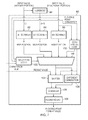
- FIG. 1 schematically illustrates an apparatus in one embodiment
- FIG. 2 shows a repeating iterative sum having an exact overlap between the integer and fractional portions of an input value, and the stages implemented by one embodiment to determine the result of the repeating iterative sum to a required precision;
- FIG. 3 schematically illustrates components and interconnections of an apparatus in one embodiment which implements the stages shown in FIG. 2 ;
- FIG. 4 shows a repeating iterative sum having non-overlapping portion between the integer and fractional portions of an input value, and the stages implemented by one embodiment to determine the result of the repeating iterative sum to a required precision;
- FIG. 5 schematically illustrates components and interconnections of an apparatus in one embodiment which implements the stages shown in FIG. 4 ;
- FIG. 6 schematically illustrates components and interconnections of an apparatus in another embodiment which implements the stages shown in FIG. 4 ;
- FIG. 7 schematically illustrates components and interconnections of a floating point converter in an apparatus in one embodiment which implements the stages shown in FIG. 4 ;
- FIG. 8 schematically illustrates an alternative configuration of some of the components and interconnections of the floating point converter shown in FIG. 7 ;
- FIG. 9 shows a repeating iterative sum having a double overlap between the integer and fractional portions of an input value, and the stages implemented by one embodiment to determine the result of the repeating iterative sum to a required precision
- FIG. 10 schematically illustrates components and interconnections of an apparatus in one embodiment which implement the earlier stages shown in FIG. 9 which reduce the double overlap to a single overlap;
- FIG. 11 schematically illustrates components and interconnections of an apparatus in one embodiment which implement the later stages shown in FIG. 9 which determine the result the result of the repeating iterative sum to a required precision;
- FIG. 12 schematically illustrates components and interconnections of a floating point converter in an apparatus in one embodiment which implements the stages shown in FIG. 9 ;
- FIG. 13A shows a repeating iterative sum having a triple overlap between the integer and fractional portions of an input value
- FIG. 13B shows the use of more than one pre-flattening procedure to reduce multiple levels of overlap in a repeating iterative sum to a snivel level of overlap
- FIG. 14 shows a sequence of steps which are taken in a method of one embodiment.
- FIG. 15 schematically illustrates a general purpose computing apparatus which is controlled by program instructions to carry out the method of one embodiment.
- the present techniques facilitate the calculation of the result value of the repeating iterative sum by “flattening” the repeating iterative sum into a flattened calculation which requires only a single iteration of addition using the input value. In an apparatus for implementing the present techniques therefore only one full adder need be provided, despite the repeating iterative sum comprising multiple additions, which facilitates a compact implementation of the apparatus.
- the present techniques are not only applicable to this particular pattern, but may equally be applied to any division where the inverse has a (sparsely) repeating binary expansion. The sparseness of the repeating binary expansion reduces the complexity of the corresponding repeating iterative sum and hence the complexity of the stages involved in the present techniques.
- a first iteration of the addition comprises addition of the input value to the shifted version of the input value
- each further iteration of the addition comprises addition of a previous iteration addition result to a further shifted version of the input value, wherein the further shifted version of the input value has the partial overlap with the previous iteration addition result.
- each of the multiple iterations of the repeating iterative sum may comprise the addition of the input value with itself, but wherein the next instance of the input value is shifted with respect to the previous instance of the input value. The shift of the next instance of the input value with respect to the previous instance of the input value gives the partial overlap between the next instance of the input value and the previous instance of the input value.
- the adder is capable of performing the sum operation to produce a sum value;
- the at least one incrementer comprises: a first incrementer capable of producing a first result portion, wherein producing the first result portion comprises incrementing a most significant portion of the input value which has the partial overlap with the shifted version of the input value using a carry result of the sum operation; and a second incrementer capable of producing a second result portion, wherein producing the second result portion comprises incrementing the sum value using the carry result of the sum operation;
- the result generator is capable of constructing the result value as the first result portion followed by at least one second result portion to give the result value to the required precision.
- an intermediate portion of the input value has no overlap with the shifted version of the input value
- the first incrementer is capable of producing the first result portion as the most significant portion of the input value which has the partial overlap incremented by an increment value
- the increment value is given by the carry result of the sum operation ANDed with a propagate value, wherein the propagate value indicates whether the intermediate portion will carry-propagate in the addition
- the second incrementer is capable of producing the second result portion as the sum value incremented by the increment value
- the result generator is capable of constructing the result value in which both the first result portion and the second result portion are suffixed by the third result portion.
- the apparatus further comprises: a third incrementer capable of producing a third result portion, wherein producing the third result portion comprises incrementing the intermediate portion by the carry result of the sum operation.
- an intermediate portion of the input value has no overlap with the shifted version of the input value
- the adder is capable of performing the sum operation to produce a sum value
- the at least one incrementer comprises: a first incrementer capable of producing a first result portion, wherein producing the first result portion comprises suffixing a most significant portion of the input value which has the partial overlap with the intermediate portion of the input value to give an first result portion input value, and incrementing the first result portion input value with a carry result of the sum operation
- a second incrementer capable of producing a second result portion, wherein producing the second result portion comprises incrementing the sum value using the carry result of the sum operation
- the result generator is capable of constructing the result value as the first result portion followed by at least one second result portion to give the result value to the required precision, wherein the at least second one result portion is suffixed by a least significant portion of the first result value having a same size as the intermediate portion of the input value.
- the apparatus further comprises: a floating point converter capable of converting the result value into a floating point format value.
- the input value comprises an integer portion and a fraction portion.
- the floating point converter comprises: a first bit position generator capable of receiving the integer portion of the input value and outputting a most significant bit position as a first bit position output value; a second bit position generator capable of outputting a most significant bit position of the integer portion of the input value incremented by one as a second bit position output value; and a third bit position generator capable of generating a position of a most significant bit in the fraction portion of the input value as a third bit position output value, wherein the floating point converter is capable of generating an exponent portion of the floating point format value using the first bit position output value when the integer portion is non-zero and the carry result is zero, using the second bit position output value when the integer portion is non-zero and the carry result is non-zero, and using the third bit position output value when the integer portion is zero.
- the second bit position generator is capable of determining whether the integer portion of the input value comprises a one immediately followed by a zero, and if it does providing the first bit position output value as the second bit position output value, and if it doesn't incrementing the first bit position output value by one to generate the second bit position output value.
- the first bit position generator, the second bit position generator, and the third bit position generator are capable of parallel operation.
- the partial overlap comprises a double self-overlap of the input value in the repeating iterative sum, the double self-overlap comprising addition of a least significant portion of the input value, an intermediate significance portion of the input value and a most significant portion of the input value in a first iteration of the repeating iterative sum, and the apparatus is capable of performing a pre-flattening operation of removing the double self-overlap for the input value in the repeating iterative sum comprising determining a replacement input value for the input value.
- the input value comprises an integer portion and a fraction portion, wherein the intermediate significance portion of the input value is a most significant portion of the fraction portion, wherein the least significant portion of the input value is a least significant portion of the fraction portion, wherein an intermediate significance portion of the fraction portion is not comprised in the double self-overlap
- the apparatus comprises: a pre-flatten adder capable of performing a pre-flatten sum operation on the most significant portion of the fraction portion and the least significant portion of the fraction portion to produce a pre-flattened sum value; a first pre-flatten incrementer capable of producing a first pre-flatten portion by incrementing the most significant portion of the fraction portion by a pre-flatten increment value, wherein the pre-flatten increment value is given by a carry result of the pre-flatten sum operation ANDed with a pre-flatten propagate value, wherein the pre-flatten propagate value indicates if the intermediate significance portion of the fraction portion will carry-propagate in the addition, a second pre-flatten increment
- the apparatus comprises: a first adder capable of performing a first sum operation on the integer portion and the first pre-flatten portion suffixed by the second pre-flatten portion to produce a first sum value; a second adder capable of performing a second sum operation on the integer portion and the third pre-flatten portion suffixed by the second pre-flatten portion to produce a second sum value; a first incrementer capable of generating a first result portion by incrementing the first sum value by a carry result of the second sum operation; a second incrementer capable of generating a second result portion by incrementing the second sum value by the carry result of the second sum operation; and a third incrementer capable of generating a third result portion by incrementing the integer portion by a further pre-flatten increment value.
- the further pre-flatten increment value is given by the pre-flatten generate value ORed with the carry result of the first sum operation ORed with an increment contribution value, wherein the increment contribution value is given by the carry result of the second sum operation ANDed with a propagate value which indicates if the first sum value will carry-propagate in the addition, and the result generator is capable of constructing the result value as the third result portion followed the first result value portion followed by at least one second result portion to give the result value to the required precision.
- the further pre-flatten increment value is given by the pre-flatten generate value added to the carry result of the first sum operation added to an increment contribution value, wherein the increment contribution value is given by the carry result of the second sum operation ANDed with a propagate value which indicates if the first sum value will carry-propagate in the addition, and the result generator is capable of constructing the result value as the third result portion followed the first result value portion followed by at least one second result portion to give the result value to the required precision.
- the third bit position generator when the most significant portion of the fraction portion is non-zero, is capable of generating the position of the most significant bit in the fraction portion of the input value as the third bit position output value using a replacement fraction portion, the replacement fraction portion comprising: the first pre-flatten portion suffixed by the second pre-flatten portion, suffixed by at least one instance of the third pre-flatten portion suffixed by the second pre-flatten portion.
- the third bit position generator when the most significant portion of the fraction portion is zero, is capable of generating the position of the most significant bit in the fraction portion of the input value as the third bit position output value using a replacement fraction portion, the replacement fraction portion comprising: the intermediate significance portion of the fraction portion suffixed by the least significant portion of the fraction portion.
- the partial overlap comprises at least a triple self-overlap of the input value in the repeating iterative sum, the triple self-overlap comprising the double self-overlap and at least one further self-overlap of the input value in the repeating iterative sum, the triple self-overlap corresponding to addition of three incrementally shifted versions of the input value to the input value at the first iteration of the repeating iterative sum, and the apparatus is capable of performing at least one further pre-flattening operation of removing the at least one further self-overlap of the input value in the repeating iterative sum comprising determining a prior replacement input value for the replacement input value.
- the apparatus is capable of performing a further pre-flattening operation in parallel with the pre-flattening operation.
- the input value represents a normalised number having a minimum absolute value of zero and a maximum absolute value of one.
- the input value has an integer component and a fraction component, and wherein to represent the maximum absolute value of the normalised number the integer component is a continuous sequence of a first type of bit value and the fraction component is a continuous sequence of a second type of bit value, wherein the second type is complementary to the first type.
- the repeating iterative sum implements multiplication by a reciprocal of a non-power-of-two constant.
- the non-power-of-two constant is expressible as an integer power-of-two minus one.
- the apparatus is capable of performing a rounding operation on the result value comprising addition of half of a last place unit to the result value.
- Some embodiments provide a computer-readable storage medium on which a computer program is stored in a non-transient fashion, the computer program for controlling a computer to carry out the method of the above-recited second aspect.
- FIG. 1 schematically illustrates a data processing apparatus 10 in one embodiment. From the components of this data processing apparatus 10 , it will be recognised that the components illustrated in FIG. 1 will typically represent only part of a larger data processing apparatus, which may for example be a general purpose data processing device (e.g. a central processing unit or a graphics processing unit).
- the data processing apparatus 10 is capable of calculating (i.e. has a configuration which enables it to calculate) a result value of a repeating iterative sum, on the basis of an input value to that repeating iterative sum, wherein the input value is added to a running total at each iteration of the repeating iterative sum (although right shifted at each iteration with respect to the previous iteration).
- Data processing apparatus 10 comprises at least one adder 11 , at least one incrementer 12 and a result generator 13 . These components operate under the general control of a control unit 14 .
- the result generator 13 may (note the dashed boundary) further comprise a floating point converter 15 which is configured to convert the result value into a floating point format result.
- the floating point converter 15 may (note the dashed boundary) itself further comprise a rounding unit 16 , to perform a rounding operation on the result value generated by the result generator.
- FIG. 2 shows one example of the format an input value which may be received by the data processing apparatus 10 of FIG. 1 , and the structure of the repeating iterative sum required to be performed to divide this example input by a constant value, which in this example is (2 8 ⁇ 1) 255.
- the structure of the repeating iterative sum is shown in box 20 in FIG. 2 .
- the input value (iiiiiiiifffffffff) in this example is an unorm8.8, i.e. an 8-bit unsigned normalised number with 8 fractional bits.
- the iterative sum shown at 20 in FIG. 2 corresponds to the division of this input value by 255 even though the input value has more than 8 bits.
- the maximum value of this unsigned normalised number i.e.
- Box 22 shows two calculations which the present techniques apply to the repeating iterative sum shown in box 20 in order to implement the calculation of the repeating iterative sum as a flattened calculation in which only a single iteration of addition using the input value is required.
- the carry out value of this sum (c) is also determined.
- Substituting d and c into the expression of box 20 gives the expression of box 24 .
- An important feature to note of the expression shown in box 20 is that when considering propagation and generation for the sum i+f, these can either generate or propagate a carry, but never both.
- a rounding of the result value may also be performed (by the rounding unit 16 in the result generator 13 ) by adding half of a last place unit to the result value. Note that it is in the nature of the infinite repeating sum that this rounding can never have a tie, since if the bits immediately below the rounding point were “10” as required to hit the tie case, then the infinitely repeating pattern ensures that there must also be further “10”s further downs the iterative sum, and so a tie can never occur.
- FIG. 3 schematically illustrates a configuration of the data processing apparatus 10 to implement the stages discussed with respect to FIG. 2 .
- “i” in FIG. 3 corresponds to the integer portion mum in FIG. 2
- “f” in FIG. 3 corresponds to the fractional portion ffffff in FIG. 2
- “I” and “D” in FIG. 3 respectively correspond to IIIIIIII and DDDDDDDD in FIG. 2 .
- the integer (i) and fractional (f) portions of the input value are received by the (full) adder 30 which produces the sum value (d) and the carry out result (c), and has a width equal to the size of the overlap (8 bits in this example).
- a first incrementer 32 receives the integer portion (i) and the carry out result (c) and increments the integer portion (i) by the carry out result (c) to generate the sum value I—the integer portion of the result value.
- a second incrementer 32 receives the sum value (d) and the carry out result (c) and increments the sum value (d) by the carry out result (c) to generate the sum value D—at least one fractional portion of the result value.
- the first incrementer 32 and second incrementer 34 have the same width as the adder 30 (i.e. 8 bits in this example). I and D are arranged into the result value by the result generator 36 .
- FIG. 4 shows another example of the format an input value which may be received by the data processing apparatus 10 of FIG. 1 , and the structure of the repeating iterative sum required to be performed to divide this example input by a constant value, which in this example is (2 10 ⁇ 1) 1023.
- the structure of the repeating iterative sum is shown in box 40 in FIG. 4 .
- the input value (iiiiiiiiffffffffff) in this example is unorm10.8, i.e. an 10-bit unsigned normalised number with 8 fractional bits, where once more the i's represent the integer portion of the input value and the f's represent the fractional part. Comparing this example to that in FIG.
- the terms a (for the overlapping part) and b (for the non-overlapping part) are substituted, as shown in box 42 .
- the present techniques apply to the repeating iterative sum shown in boxes 40 and 42 in order to implement the calculation of the repeating iterative sum as a flattened calculation in which only a single iteration of addition using the input value is required, namely those shown in box 44 .
- the carry out value of this sum (c) is also determined.
- Box 48 shows the three incrementing calculations which are performed in this example.
- An incrementing term is generated as (generate (a+f) && propagate (b)), i.e. (c && propagate(b)), and this is used to increment each of a (the overlapping portion of the integer part of the input value) and d (the overlapping portion of the integer part of the input value) to give A and D respectively.
- the non-overlapping portion of the integer part of the input value (b) is incremented by generate (a+f), i.e. c.
- the expression in box 46 this can thus be substituted for by the expressions shown in box 48 , to give the expression shown in box 50 (where it is the DB term which infinitely repeats).
- the data processing apparatus evaluates the expression of box 50 to the required precision for the result, i.e. truncating the expression at the point at which such required precision in the result value is achieved.
- a rounding of the result value may also be performed by the rounding unit 16 in the result generator 13 .
- FIG. 5 schematically illustrates a configuration of the data processing apparatus 10 to implement the stages discussed with respect to FIG. 4 .
- the same style of abbreviated notation is used here, where “a” in FIG. 5 corresponds to the overlapping integer portion in FIG. 4 , “b” in FIG. 5 corresponds to the non-overlapping integer portion in FIG. 4 and “f” in FIG. 5 corresponds to the fractional portion in FIG. 4 .
- “A”, “B” and “D” in FIG. 5 respectively correspond to AAAAAAAA, BB and DDDDDDDD in FIG. 4 .
- the overlapping integer (a) and fractional (f) portions of the input value are received by the (full) adder 60 which produces the sum value (d) and the carry out result (c), and has a width equal to the size of the overlap (8 bits in this example).
- the non-overlapping integer portion (b) of the input value is received by the propagation detection circuitry 62 , which determines if the bit values of b will propagate a set carry value.
- the result of this propagation detection and the carry out result (c) provide the inputs to the AND gate 64 , the output of which is passed to the incrementers 66 and 68 .
- the first incrementer 66 increments the overlapping integer portion (a) by the AND gate output to generate the sum value A—a first part of the integer portion of the result value.
- the second incrementer 32 increments the sum value (d) by the AND gate output to generate the sum value D—a first part of at least one fractional portion of the result value.
- the first incrementer 66 and second incrementer 68 have the same width as the adder 60 corresponding to the size of the overlap (i.e. 8 bits in this example).
- a third incrementer 70 is provided in this example and increments the non-overlapping integer portion (b) by carry out result (c) to generate the sum value B—a second part of both the integer and fractional portion of the result value.
- A, B and D are arranged into the result value by the result generator 72 .
- FIG. 6 schematically illustrates an alternative configuration to the structure shown in FIG. 4 , in which the incrementers 66 and 70 have been merged into a single first incrementer 74 .
- the adder 60 , propagate detection unit 62 , AND gate 64 and second incrementer 68 are themselves unchanged, although the path from the AND gate 64 to the first incrementer 66 has been removed, and the carry out value (c) and the non-overlapping integer part (b) are now provided as inputs to the first incrementer 74 .
- AB (and where required just the B portion) and D are arranged into the result value by the result generator 76 .
- This alternative arrangement is based on the recognition that for the full integer portion of the input value in the example of FIG.
- FIG. 7 schematically illustrates an example of the floating point converter 15 shown in FIG. 1 , which may be used to convert the result value generated by the example configurations of the apparatus discussed with reference to FIGS. 2-6 .
- the floating point converter is labelled 80 .
- the result value In order to convert the result value into a floating point format, it needs to be scanned to find the most significant set bit, and then the result value needs shifting accordingly to generate the mantissa of the floating point format value. A corresponding exponent value is also generated.
- the bit scanning is improved by the present techniques using some observations of the calculations described above. There are three cases, and a bit scanner may be provided for each (as is the case in FIG. 7 ):
- the most significant bit positions generated by the respective bit scanners are selected between by the multiplexer 98 under the control of the selection logic 100 .
- the selection logic 100 receives the integer portion of the input value (in order to determine whether it is zero or non-zero) as well as the fractional portion of the input value, for the special case in which both the integer portion and fraction portion are zero.
- zero special case unit 102 is provided, which can provide specially selected values to the shifter 104 (via the multiplexer 98 ) and the exponent generation unit 106 , these specially selected values being used to indicate the “all zero” special case in the output.
- the selection logic 100 also receives the carry from the sum stage to be able to select between the results from bit scanners 82 and 84 .
- the result value from the result generator 13 (in whichever of the above described configurations it may take) is received by the shifter 104 , which shifts this value by the appropriate amount in dependence on the most significant bit (MSB) position received from the multiplexer 98 .
- the zero special case unit 102 may provide the shifter 104 with a replacement value for the result value, as necessary to generate the specially selected value being used to indicate this zero special case.
- the output of the multiplexer 98 (and an appropriate signal from the zero special casing 102 ) are received by the exponent generation unit 106 .
- the outputs of the shifter 104 and exponent generation unit 106 are received by the combiner 108 which put these together into the floating point format output value.
- This floating point format output value may be rounded by the rounding unit 109 , for example by rounding the complete floating point number so that it overflows into the exponent (i.e. without having to treat the exponent separately)
- the rounding unit 109 may be rounded by the rounding unit 109 , for example by rounding the complete floating point number so that it overflows into the exponent (i.e. without having to treat the exponent separately)
- multiple shifters may be provided, in which case the multiplexer 98 is then provided after these multiple shifters.
- the shifter following bit scanner 96 can use the fractional part of the primary input as the value to shift. For the all-zero case, no shifting is required.
- FIGS. 9 to 12 an example is presented (for an unorm6.8 input value) in which there is a double overlap in the repeating iterative sum, i.e. there are places where 3 bits need to be added.
- the structure of the repeating iterative sum is shown in box 120 in FIG. 9 .
- the “flattening” of the calculation of the present techniques is done in two stages for this example, firstly using the technique from the single overlap case to flatten the fractional bits, and then using the same technique again to flatten the sum totally.
- the input is being divided by a constant value which is (2 6 ⁇ 1) 63.
- An incrementing term is generated as the carry out value (generate (i+DB)) from the (i+DB addition) and this is used to increment each of e and j to give E and F respectively.
- the integer part of the input value (i) is incremented by an increment term which represents the ability for a carry value to be propagated into this integer part of the input value.
- the ORing of the G term with the remainder of the terms is also based on observation 3 above, related to the above-mentioned representation for the maximum value of 1.0. In the more general case where such representation is not used, the G term would be ADDed with the remainder of the terms. Note that therefore when ORing the G term with the remainder of the terms a new MSB cannot be generated for the integer term, but this is possible when ADDing the G term with the remainder of the terms (and when the integer term is all ones).
- the expression in box 126 can thus be substituted for by the expressions shown in box 128 , to give the expression shown in box 130 (where it is the FFFFFF term which infinitely repeats).
- the expression shown in box 130 is thus a fully flattened calculation which implements the repeating iterative sum shown in box 120 .
- the data processing apparatus evaluates the expression of box 130 to the required precision for the result, i.e. truncating the expression at the point at which such required precision in the result value is achieved.
- a rounding of the result value may also be performed by the rounding unit 16 in the result generator 13 .
- FIGS. 10 and 11 schematically illustrates a configuration of the data processing apparatus 10 to implement the stages discussed with respect to FIG. 9 .
- a in FIG. 10 corresponds to the aa term in FIG. 9 , and so on.
- the a and c portions of the input value are received by the (full) adder 140 which produces the sum value (d) and the carry out result.
- the adder 140 is thus only required to have a width equal to the size of the overlap between the two at this stage (2 bits in this example), but this adder may be reused for a later stage (see FIG.
- adder 140 may have the width required at that later stage so that it can be reused there.
- the b portion of the input value is received by the propagation detection circuitry 142 , which determines if the bit values of b will propagate a set carry value.
- the result of this propagation detection and the carry out result from adder 140 provide the inputs to the AND gate 64 , the output of which is passed to the incrementers 148 and 150 .
- the a term is also received by the further propagate detection circuitry 146 , which determines if the bit values of a will propagate a set carry value.
- the first incrementer 148 increments the a term by the AND gate 144 output to generate the sum value A.
- the second incrementer 150 increments the sum value d by the AND gate 144 output to generate the sum value D.
- the third incrementer 152 increments the b term by carry output from the adder 140 to generate the sum value B.
- the AND gate 154 has inputs from the AND gate 144 and the propagate detection circuitry 146 to generate the G value.
- the incrementers 148 , 150 and 152 need only have the same width as the their respective inputs at this stage, but may be reused at a further stage (see FIG. 11 ) and in that case have the largest width required for their role in either stage.
- A, B and D may be arranged into intermediate result values AB and DB by the result generator 156 , but may also be taken directly into the next stage (see FIG. 11 ) without any explicit rearrangement and fed into the required inputs as parallel bit sets.
- the i and DB terms are received by the (full) adder 160 which produces the sum value (j) and the carry out result.
- the i and AB terms are received by the (full) adder 162 which produces the sum value (e) and the carry out result.
- one of these adders may in fact be the same as adder 140 , being reused at this stage, and this configuration corresponds to the feedback path shown in FIG. 1 where the output of the result generator 13 is passed back to the input of the full adder(s) 11 , thus forming a replacement input value.
- the G term is received by the OR gate 164 .
- the carry output of the adder 162 provides the other input the OR gate 164 .
- the sum output of the adder 162 ( e ) provides the input to the propagation detection circuitry 166 , which determines if the bit values of (e) will propagate a set carry value.
- the result of this propagation detection and the carry out result from adder 160 provide the inputs to the AND gate 168 , the output of which is provides one input to the OR gate 170 .
- Note that the output of AND gate 168 and the carry output of the adder 162 are also passed to the floating point selection logic of FIG. 12 (discussed below).
- the first incrementer 172 increments the j term by the carry output of adder 160 to generate the sum value F.
- the second incrementer 174 increments the e term by the carry output of adder 160 to generate the sum value E.
- the third incrementer 176 increments the i term by the output of the OR gate 170 to generate the sum value I.
- I, E and F are arranged into the final result value by the result generator 178 .
- FIG. 12 schematically illustrates an example of the floating point converter 15 shown in FIG. 1 , which may be used to convert the result value generated by the example configurations of the apparatus discussed with reference to FIGS. 9-11 .
- the result value As before in order to convert the result value into a floating point format, it needs to be scanned to find the most significant set bit, and then the result value needs shifting accordingly to generate the mantissa of the floating point format value and a corresponding exponent value is also generated.
- This bit scanning is also improved by the present techniques using some further observations of the calculations described above with respect to FIGS. 9-11 .
- a bit scanner may be provided for each (as is the case in FIG. 12 ):
- the result value from the result generator 178 are received by the shifter 204 which shifts the appropriate value (as signaled by the section logic 202 ) by the appropriate amount in dependence on the most significant bit (MSB) position received from the multiplexer 200 .
- the output of the multiplexer 200 is received by the exponent generation unit 206 .
- the outputs of the shifter 204 and exponent generation unit 206 are received by the combiner 208 which put these together into the floating point format output value.
- a rounding unit 209 may also be provided, as described above with respect to unit 109 in FIG. 7 .
- multiple shifters may be provided before the multiplexer 200 instead of the single shifter 204 , allowing for each shifter to handle a smaller shift amount.
- FIG. 13A shows an example in which there is a triple overlap in the repeating iterative sum, i.e. there are places where 4 bits need to be added.
- the “flattening” of the calculation of the present techniques is done in multiple stages for this example, using the single overlap technique to separately flatten one level of fractional bits overlap, and for one level of integer/fractional overlap. Then the same technique can be used again to completely flatten the iterative sum.
- These multiple stages may be implemented at least partially in parallel as shown in FIG. 13B , where a tree structure is used to perform multiple flattenings and bring their results together.
- the present techniques may even be applied to more than a triple overlap as the additional (dashed box) pre-flatten stages in FIG. 13B show.
- FIG. 14 shows a sequence of steps which are taken in the method of one embodiment.
- the flow begins at step 220 where the input value is received and it is determined what the required format of the result value is. Then, at step 222 , it is determined if there is more than a single level of overlap the repeating iterative sum. If there is, then the flow proceeds to step 224 , where a pre-flattening operation is performed to remove one level of overlap. The flow then returns to step 222 to determine if this has resulted in only a single level of overlap remaining in the iterative sum, with the possibility of returning to step 224 as many times as necessary until only a single level of overlap remains.
- step 226 it is determined if there is exact overlap between the integer and fractional portions of the input value (or the replacement input value if step 224 has been used at least once). If the overlap between these portions is exact then the flow proceeds to step 228 where the integer and fractional portions are added to produce a sum value. Then, at step 230 , the integer portion is incremented by the carry output of the sum operation to give the first part of the result value. Then at step 232 the sum is incremented by the carry output of the sum operation to give the second part(s) of the result value. Note that the increment steps 230 and 232 do not need to be carried out sequentially and, as is illustrated in FIG. 3 can indeed be carried out in parallel. Finally, at step 234 the result value is extended by as many additional second parts as required to produce the result value with the desired precision.
- step 236 the overlap part of the integer portion and the fractional portion are added to give a sum value.
- step 238 it is determined if the non-overlapping part of the integer portion will propagate, this being represented by a propagate result.
- this propagate result is ANDed with the carry output of the sum operation and at step 242 the overlapping part of the integer portion is incremented by the AND result (of step 240 ) to give the first part of the result value.
- step 244 the non-overlapping integer portion is incremented by the carry output of the sum operation to give the second part of the result value.
- step 246 the sum value is incremented by the AND result to give the third part of the result value.
- steps 242 , 244 and 246 do not need to be carried out sequentially and as illustrated in FIG. 5 can indeed be carried out in parallel.
- step 248 the result value is extended by as many additional second and third parts (alternating) as required to give a result value of the desired precision.
- FIG. 15 schematically illustrates a general purpose computing device 300 of the type that may be used to implement the above described techniques.
- the general purpose computing device 300 includes a central processing unit 302 , a random access memory 304 and a read only memory 306 , connected together via bus 322 . It also further comprises a network interface card 308 , a hard disk drive 310 , a display driver 312 , a monitor 314 and a user input/output circuit 316 with a keyboard 318 and mouse 320 all connected via the common bus 322 .
- the central processing unit 302 will execute computer program instructions that may for example be stored in the random access memory 304 and/or the read only memory 306 .
- Computer program instructions could be additionally retrieved from the hard disk drive 310 or dynamically downloaded via the network interface card 308 .
- the RAM 304 , the ROM 306 , the hard disk drive 310 and any storage medium accessed via the network interface card 308 thus each represent a computer-readable storage medium on which a computer program is stored in a non-transient fashion.
- the results of the processing performed may be displayed to a user via the display driver 312 and monitor 314 .
- User inputs for controlling the operation of the general purpose computing device 300 may be received via the user input output circuit 316 from the keyboard 318 or the mouse 320 . It will be appreciated that the computer program could be written in a variety of different computer languages.
- the computer program may be stored locally on a recording medium or dynamically downloaded to the general purpose computing device 300 .
- the general purpose computing device 300 can perform the above described techniques and can be considered to form an apparatus for performing the above described techniques.
- the architecture of the general purpose computing device 300 could vary considerably and FIG. 15 is only one example.
- an apparatus, method and program for calculating a result value to a required precision of a repeating iterative sum, wherein the repeating iterative sum comprises multiple iterations of an addition using an input value.
- Addition is performed in a single iteration of addition as a sum operation using overlapping portions of the input value and a shifted version of the input value, wherein the shifted version of the input value has a partial overlap with the input value.
- At least one result portion is produced by incrementing an input derived from the input value using the output from the sum operation and the result value is constructed using the at least one result portion to give the result value to the required precision.
- the repeating iterative sum is thereby flattened into a flattened calculation which requires only a single iteration of addition using the input value, thus facilitating the calculation of the result value of the repeating iterative sum.
Landscapes
- Engineering & Computer Science (AREA)
- Physics & Mathematics (AREA)
- General Physics & Mathematics (AREA)
- Theoretical Computer Science (AREA)
- Computational Mathematics (AREA)
- Mathematical Analysis (AREA)
- Pure & Applied Mathematics (AREA)
- Mathematical Optimization (AREA)
- Computing Systems (AREA)
- General Engineering & Computer Science (AREA)
- Complex Calculations (AREA)
Abstract
Description
For example for an unorm6, the formula is
The division by a small non-power-of-two constant may be required when multiplying two normalized values, or when converting to floating point or fixed-point values. One way to perform such a division is to multiply by
yet this multiplication is rather expensive, for example in terms of the area of the apparatus which needs to be provided to support such a multiplication.
have a binary expansion of the
-
- 1. If the integer part of the result value is non-zero, and no carry is generated. The primary integer input can then be bit-scanned to generate the shift amount. This is done by the
bit scanner 82. The result of the addition(s) is still needed to actually shift, but the bit scanning can be done in parallel to the addition(s). - 2. If the integer part of the result value is non-zero, and a carry is generated. The value (i+1) can be calculated in advance, and this value is then bit scanned. This is done by the
bit scanner 84, theincrementer 86. Alternatively (as shown in thebit scanner 88 inFIG. 8 ) the result fromcase 1 can be used, and it can be checked whether adding 1 to the integer part would change the bit scan result. If the integer part of the primary input contains the bit pattern “10”, then adding one to it will not change the bit scan result. If it doesn't then adding one will add one to the bit scan result. Thisalternative bit scanner 88 thus comprises “10”detection unit 90, andincrementer 92 and themultiplexer 94. The result of the “10” detection controls which input of the multiplexer is output, i.e. the unamended result from thebit scanner 82 or the result from thebit scanner 82 incremented by one. This has a lower logic depth than increment-then-scan. Again, the result of the addition(s) is still needed to actually shift, but the bit scanning can be done in parallel to the addition(s). - 3. The integer part is zero. This removes the actual additions. The primary fractional input can then be scanned (performed by the bit scanner 96), and the shift is performed using only unmodified inputs. There is also some special casing for zero on this path.
- 1. If the integer part of the result value is non-zero, and no carry is generated. The primary integer input can then be bit-scanned to generate the shift amount. This is done by the
-
- 1. If (AB) were to propagate a carry (i.e. G is non-zero), then AB must be zero as a result of that propagation; adding i and G will then not generate a carry;
- 2. If (AB) is zero, then a carry from (i+DB) would only propagate through the (i+AB) sum if the integer term iiiiii is all ones. This cannot happen for this particular case, in which the above-mentioned representation is used in which the maximum value of 1.0 for a unorm value is given by the integer bits being all ones and the fractional bits being all zero, and hence the fractional bits must be all zeroes if the integer bits are all-ones;
- 3. If (AB) is non-zero, then a carry might be generated from (i+AB) or a carry might be propagated through (i+AB) from the (i+DB) sum, but not both;
- 4. In no cases can the overall carry into the first i be more than one.
-
- 1. If the integer part of the result value is non-zero, and no carry propagates into it, then as in the
FIG. 7 example the primary integer input can be bit-scanned to generate the shift amount. This is done by thebit scanner 190. The result of the additions is still needed to actually shift, but the bit scanning can be done in parallel to those additions. - 2. If the integer part of the result value is non-zero, and a carry propagates into it, then as in the
FIGS. 7 and 8 examples the same two possibilities exist, namely either to bit scan the primary integer input plus one, or detect if thecase 1 result is affected by the carry. Only the first example is shown here, as implemented by thebit scanner 192 and theincrementer 194. - 3. If the integer part is zero, and a is non-zero, then the result of flattening the carry (ABDB), i.e. the full fractional part, can be bit scanned and this term is also use this for shifting, since the final addition with the integer part will have no effect since it is zero. This is implemented by the
bit scanner 196 and the path taking the ABDB term to theshifter 204. - 4. If the integer part is zero, and a is zero then the primary input bc can be bit scanned and also used for the shifting. Since no additions have any effect, this can be done in parallel with everything else. This is implemented by the
bit scanner 198 and the path taking the bc term to theshifter 204.
- 1. If the integer part of the result value is non-zero, and no carry propagates into it, then as in the
Claims (26)
Applications Claiming Priority (2)
| Application Number | Priority Date | Filing Date | Title |
|---|---|---|---|
| GB1419456.7A GB2535426B (en) | 2014-10-31 | 2014-10-31 | Apparatus, method and program for calculating the result of a repeating iterative sum |
| GB1419456.7 | 2014-10-31 |
Publications (2)
| Publication Number | Publication Date |
|---|---|
| US20160124708A1 US20160124708A1 (en) | 2016-05-05 |
| US9933999B2 true US9933999B2 (en) | 2018-04-03 |
Family
ID=52118541
Family Applications (1)
| Application Number | Title | Priority Date | Filing Date |
|---|---|---|---|
| US14/878,562 Active 2036-06-03 US9933999B2 (en) | 2014-10-31 | 2015-10-08 | Apparatus, method and program for calculating the result of a repeating iterative sum |
Country Status (4)
| Country | Link |
|---|---|
| US (1) | US9933999B2 (en) |
| KR (1) | KR102486711B1 (en) |
| CN (1) | CN105573712B (en) |
| GB (1) | GB2535426B (en) |
Families Citing this family (4)
| Publication number | Priority date | Publication date | Assignee | Title |
|---|---|---|---|---|
| US11281463B2 (en) * | 2018-03-25 | 2022-03-22 | Intel Corporation | Conversion of unorm integer values to floating-point values in low power |
| CN108897522A (en) * | 2018-06-14 | 2018-11-27 | 北京比特大陆科技有限公司 | Data processing method, data processing equipment and electronic equipment |
| CN117296062A (en) * | 2021-04-21 | 2023-12-26 | 上海科技大学 | Method and system for multiplier sharing in neural networks |
| CN113721884B (en) * | 2021-09-01 | 2022-04-19 | 北京百度网讯科技有限公司 | Operation method, operation device, chip, electronic device and storage medium |
Citations (3)
| Publication number | Priority date | Publication date | Assignee | Title |
|---|---|---|---|---|
| US5243552A (en) | 1990-06-19 | 1993-09-07 | Sony Corporation | Coefficient multiplying circuit |
| US20060095496A1 (en) | 2004-11-01 | 2006-05-04 | Luke Fay | Power of two multiplication engine |
| US7257609B1 (en) | 2000-10-16 | 2007-08-14 | Nokia Corporation | Multiplier and shift device using signed digit representation |
Family Cites Families (6)
| Publication number | Priority date | Publication date | Assignee | Title |
|---|---|---|---|---|
| US7099410B1 (en) * | 1999-01-26 | 2006-08-29 | Ericsson Inc. | Reduced complexity MLSE equalizer for M-ary modulated signals |
| CN1375765A (en) * | 2001-03-19 | 2002-10-23 | 深圳市中兴集成电路设计有限责任公司 | Fast large-scale multiplying circuit |
| US7296049B2 (en) * | 2002-03-22 | 2007-11-13 | Intel Corporation | Fast multiplication circuits |
| JP4571903B2 (en) * | 2005-12-02 | 2010-10-27 | 富士通株式会社 | Arithmetic processing apparatus, information processing apparatus, and arithmetic processing method |
| CN101227613B (en) * | 2008-01-22 | 2010-04-07 | 炬力集成电路设计有限公司 | SAD arithmetic processing device and method |
| CN101866278B (en) * | 2010-06-18 | 2013-05-15 | 广东工业大学 | A 64-bit integer multiplier with asynchronous iteration and its calculation method |
-
2014
- 2014-10-31 GB GB1419456.7A patent/GB2535426B/en active Active
-
2015
- 2015-10-08 US US14/878,562 patent/US9933999B2/en active Active
- 2015-10-23 KR KR1020150147724A patent/KR102486711B1/en active Active
- 2015-10-28 CN CN201510713139.5A patent/CN105573712B/en active Active
Patent Citations (3)
| Publication number | Priority date | Publication date | Assignee | Title |
|---|---|---|---|---|
| US5243552A (en) | 1990-06-19 | 1993-09-07 | Sony Corporation | Coefficient multiplying circuit |
| US7257609B1 (en) | 2000-10-16 | 2007-08-14 | Nokia Corporation | Multiplier and shift device using signed digit representation |
| US20060095496A1 (en) | 2004-11-01 | 2006-05-04 | Luke Fay | Power of two multiplication engine |
Non-Patent Citations (8)
| Title |
|---|
| "Integer Division by Constants", 10-17 Methods Not Using Multiply High, Hackers Delight, Chapter 10, Dec. 30, 2003, 28 pages. |
| Alverson, "Integer Division using Reciprocals", Proceedings of the Tenth Symposium on Computer Arithmetic, Jun. 1991, 5 pages. |
| Dinechin et al., "Table-Based Division by Small Integer Constants", Applied Reconfigurable Computing, Mar. 2012, pp. 53-63. |
| Drane et al., "Correctly Rounded Constant Integer Division via Multiply-Add", Imagination Technologies Ltd., Circuits and Systems (ISCAS), 2012 IEEE International Symposium, May 20-23, 2012, 4 pages. |
| Granlund et al., "Division by Invariant Integers using Multiplication", Proceedings of the SIGNPLAN '94 Conference on Programming Language Design and Implementation, Aug. 1994, 12 pages. |
| Li, "Fast Constant Division Routines", IEEE, vol. c-34, No. 9, Sep. 1985, pp. 866-869. |
| Schwartzbacher et al., "Constant Divider Structures of the Form 2n±1", Reprint of Irish Signals and Systems Conference 2000, Jun. 2000, pp. 368-375. |
| Search Report for GB 1419456.7, dated May 1, 2015, 3 pages. |
Also Published As
| Publication number | Publication date |
|---|---|
| KR20160051616A (en) | 2016-05-11 |
| CN105573712B (en) | 2020-09-04 |
| CN105573712A (en) | 2016-05-11 |
| GB201419456D0 (en) | 2014-12-17 |
| KR102486711B1 (en) | 2023-01-10 |
| GB2535426A (en) | 2016-08-24 |
| US20160124708A1 (en) | 2016-05-05 |
| GB2535426B (en) | 2021-08-11 |
Similar Documents
| Publication | Publication Date | Title |
|---|---|---|
| Mohan et al. | Residue number systems | |
| CN105468331B (en) | Independent floating point conversion unit | |
| USRE39385E1 (en) | Method and apparatus for performing mathematical functions using polynomial approximation and a rectangular aspect ratio multiplier | |
| KR102627299B1 (en) | Apparatus and method for floating-point multiplication | |
| CN106250098B (en) | Apparatus and method for controlling rounding when performing floating point operations | |
| CN103809930B (en) | Design method of double-precision floating-point divider and divider | |
| Hormigo et al. | New formats for computing with real-numbers under round-to-nearest | |
| US9785407B2 (en) | Data processing apparatus having combined divide-square root circuitry | |
| US9933999B2 (en) | Apparatus, method and program for calculating the result of a repeating iterative sum | |
| Hormigo et al. | Measuring improvement when using HUB formats to implement floating-point systems under round-to-nearest | |
| CN108334304B (en) | Digital recursive division | |
| Teja et al. | FPGA implementation of low-area floating point multiplier using Vedic mathematics | |
| Srinath et al. | Automatic generation of high-performance multipliers for FPGAs with asymmetric multiplier blocks | |
| Thompson et al. | An IEEE 754 double-precision floating-point multiplier for denormalized and normalized floating-point numbers | |
| US11119731B2 (en) | Apparatus and method for rounding | |
| Muller et al. | Hardware implementation of floating-point arithmetic | |
| Senturk et al. | Sequential large multipliers on FPGAs | |
| Amaricai et al. | SRT radix-2 dividers with (5, 4) redundant representation of partial remainder | |
| JP2761145B2 (en) | Square root arithmetic unit | |
| Dave et al. | Multiplication by complements | |
| US20240248683A1 (en) | Mixed-precision multiplication circuit | |
| Piso et al. | Obtaining accurate error expressions and bounds for floating-point multiplicative algorithms | |
| Villalba-Moreno et al. | Floating point square root under HUB format | |
| Mahzoon et al. | Systematic design space exploration of floating-point expressions on FPGA | |
| Michard et al. | Divgen: a divider unit generator |
Legal Events
| Date | Code | Title | Description |
|---|---|---|---|
| AS | Assignment |
Owner name: ARM LIMITED, UNITED KINGDOM Free format text: ASSIGNMENT OF ASSIGNORS INTEREST;ASSIGNORS:ENGH-HALSTVEDT, ANDREAS DUE;FIELDING, EDVARD;REEL/FRAME:036759/0715 Effective date: 20150930 |
|
| STCF | Information on status: patent grant |
Free format text: PATENTED CASE |
|
| AS | Assignment |
Owner name: ARM LIMITED, UNITED KINGDOM Free format text: ASSIGNMENT OF ASSIGNORS INTEREST;ASSIGNOR:PEDERSEN, RONNY;REEL/FRAME:046113/0004 Effective date: 20180608 |
|
| CC | Certificate of correction | ||
| MAFP | Maintenance fee payment |
Free format text: PAYMENT OF MAINTENANCE FEE, 4TH YEAR, LARGE ENTITY (ORIGINAL EVENT CODE: M1551); ENTITY STATUS OF PATENT OWNER: LARGE ENTITY Year of fee payment: 4 |
|
| MAFP | Maintenance fee payment |
Free format text: PAYMENT OF MAINTENANCE FEE, 8TH YEAR, LARGE ENTITY (ORIGINAL EVENT CODE: M1552); ENTITY STATUS OF PATENT OWNER: LARGE ENTITY Year of fee payment: 8 |