US9932895B2 - Radial passage engine wash manifold - Google Patents
Radial passage engine wash manifold Download PDFInfo
- Publication number
- US9932895B2 US9932895B2 US14/511,741 US201414511741A US9932895B2 US 9932895 B2 US9932895 B2 US 9932895B2 US 201414511741 A US201414511741 A US 201414511741A US 9932895 B2 US9932895 B2 US 9932895B2
- Authority
- US
- United States
- Prior art keywords
- engine
- feeder body
- manifold assembly
- manifold
- wash
- Prior art date
- Legal status (The legal status is an assumption and is not a legal conclusion. Google has not performed a legal analysis and makes no representation as to the accuracy of the status listed.)
- Active, expires
Links
Images


Classifications
-
- F—MECHANICAL ENGINEERING; LIGHTING; HEATING; WEAPONS; BLASTING
- F02—COMBUSTION ENGINES; HOT-GAS OR COMBUSTION-PRODUCT ENGINE PLANTS
- F02B—INTERNAL-COMBUSTION PISTON ENGINES; COMBUSTION ENGINES IN GENERAL
- F02B77/00—Component parts, details or accessories, not otherwise provided for
- F02B77/04—Cleaning of, preventing corrosion or erosion in, or preventing unwanted deposits in, combustion engines
-
- B—PERFORMING OPERATIONS; TRANSPORTING
- B64—AIRCRAFT; AVIATION; COSMONAUTICS
- B64F—GROUND OR AIRCRAFT-CARRIER-DECK INSTALLATIONS SPECIALLY ADAPTED FOR USE IN CONNECTION WITH AIRCRAFT; DESIGNING, MANUFACTURING, ASSEMBLING, CLEANING, MAINTAINING OR REPAIRING AIRCRAFT, NOT OTHERWISE PROVIDED FOR; HANDLING, TRANSPORTING, TESTING OR INSPECTING AIRCRAFT COMPONENTS, NOT OTHERWISE PROVIDED FOR
- B64F5/00—Designing, manufacturing, assembling, cleaning, maintaining or repairing aircraft, not otherwise provided for; Handling, transporting, testing or inspecting aircraft components, not otherwise provided for
- B64F5/30—Cleaning aircraft
-
- F—MECHANICAL ENGINEERING; LIGHTING; HEATING; WEAPONS; BLASTING
- F01—MACHINES OR ENGINES IN GENERAL; ENGINE PLANTS IN GENERAL; STEAM ENGINES
- F01D—NON-POSITIVE DISPLACEMENT MACHINES OR ENGINES, e.g. STEAM TURBINES
- F01D25/00—Component parts, details, or accessories, not provided for in, or of interest apart from, other groups
- F01D25/002—Cleaning of turbomachines
-
- B—PERFORMING OPERATIONS; TRANSPORTING
- B08—CLEANING
- B08B—CLEANING IN GENERAL; PREVENTION OF FOULING IN GENERAL
- B08B3/00—Cleaning by methods involving the use or presence of liquid or steam
- B08B3/02—Cleaning by the force of jets or sprays
-
- F—MECHANICAL ENGINEERING; LIGHTING; HEATING; WEAPONS; BLASTING
- F02—COMBUSTION ENGINES; HOT-GAS OR COMBUSTION-PRODUCT ENGINE PLANTS
- F02B—INTERNAL-COMBUSTION PISTON ENGINES; COMBUSTION ENGINES IN GENERAL
- F02B77/00—Component parts, details or accessories, not otherwise provided for
- F02B77/04—Cleaning of, preventing corrosion or erosion in, or preventing unwanted deposits in, combustion engines
- F02B2077/045—Cleaning of, preventing corrosion or erosion in, or preventing unwanted deposits in, combustion engines by flushing or rinsing
Definitions
- the present invention relates generally to systems and methods for washing engines, and more particularly to systems and methods of washing gas turbine engines having radial passages at or near an engine inlet.
- gas turbine engines become subject to buildup of contaminants on engine components. These contaminants can affect engine components and overall performance of the engine. Engine washing can help to remove these contaminants and improve engine performance and efficiency.
- washing can be done by connecting a manifold to an inlet of the engine, and introducing a fluid to the inlet of the engine.
- the engine is cranked and the airflow from the fan carries the wash fluid through the various sections of the engine, including the compressor.
- the wash fluid removes contaminants as it flows through the engine.
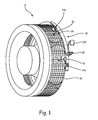
- FIG. 1 is a perspective view of an engine wash manifold connected to a portion of an engine.
- FIG. 2A is a perspective view of the engine wash manifold of FIG. 1 from a forward position, shown in isolation.
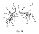
- FIG. 2B is a perspective view of the engine wash manifold of FIG. 1 from a back position, shown in isolation.
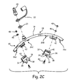
- FIG. 2C is an exploded view of the engine wash manifold of FIG. 1 , shown in isolation.
- FIG. 2D is an enlarged view a portion of the engine wash manifold and the portion of the engine of FIG. 1 .
- FIG. 3A is a partial side perspective view of another embodiment of an engine wash manifold connected to a portion of an engine assembly.
- FIG. 3B is a forward perspective view of the embodiment of the engine wash manifold and the engine assembly of FIG. 3A .
- FIG. 4 is a perspective view of another embodiment of an engine wash manifold connected to a portion of an engine.
- FIG. 5 is a perspective view of another embodiment of an engine wash manifold connected to a portion of an engine.
- FIG. 6 is a perspective view of another embodiment of an engine wash manifold connected to a portion of an engine.
- FIG. 7 is a perspective view of another embodiment of an engine wash manifold connected to a portion of an engine.
- FIG. 8 is a perspective view of another embodiment of an engine wash manifold connected to a portion of an engine.
- FIG. 9 is a perspective view of yet another embodiment of an engine wash manifold connected to a portion of an engine.
- FIG. 1 is a perspective view of one embodiment of engine wash manifold 10 connected to engine 12 (only a portion of which is illustrated) with inlet screen 14 and inlet passageways ducts 16 that extend in a generally radial direction.
- engine 12 is a turboprop engine, though in further embodiments it should be understood that other types of engine configurations are possible, and the present invention can be applied to gas turbine engines for helicopters, auxiliary power units (APUs), prop fan engines, low and high bypass ratio jet engines, industrial gas turbine power plants, military tanks, ships and the like.
- APUs auxiliary power units
- Turboprop engine 12 is illustrated in FIG. 1 as a Propeller Turbine 6 “PT6” engine (available from Pratt & Whitney Canada, Longueuil, Quebec, Canada) and includes a compressor section (not shown) which is located radially inward from inlet screen 14 inside of inlet ducts 16 .
- PT6 Propeller Turbine 6
- inlet ducts 16 receive airflow, which is fed to the compressor, and subsequently flows to other parts of the engine.
- this airflow can contain contaminants which can remain in the engine and can negatively affect overall engine performance.
- Manifold 10 is shaped to hold nozzles securely in place for an engine 12 wash operation, and to provide delivery of wash fluid at relatively high pressures (e.g., 200-1000 psi [1.379-6.895 megapascal] or more).
- Manifold 10 can be made of metal, such as stainless steel and coated in part or in whole with a polymer type coating to prevent scratching or marring of surfaces when attaching manifold 10 to engine 12 .
- Manifold 10 connects to inlet screen 14 to suitably direct wash fluid into inlet ducts 16 to clean contaminants within compressor and other components of engine 12 .
- the process of delivering a wash fluid is highly complex, and can involve precise positioning of manifold 10 relative to engine 12 to provide, for instance, wash fluid atomization and dispersion and entrainment in intake airflows, in order to help promote effectively delivery of the wash fluid such that, for instance, an entire span of internal engine airfoils are wetted and cleaned.
- Effective positioning and fluid pressure are particularly important in helping to regulate droplet (or particle) size of the wash fluid, as small dimensions tend to cause the wash fluid to undesirably undergo a phase change and large dimensions cause centrifugal action in engine 12 to more outward without desired dispersion.
- Washing liquid is typically atomized prior to entering a compressor of engine 12 for enhanced penetration into the compressor.
- the atomized droplets generally collide with gas path components such as rotor blades and stator vanes.
- the impingement of the droplets results in surface wetting and, when at least when the wash fluid include a liquid, in establishing of a liquid film.
- the deposited particles on the gas path components are released by mechanical and/or chemical action of the wash fluid.
- Wash fluid penetration into the compressor is further enhanced by allowing the rotor shaft to rotate during washing. This can be done by letting the engine's starter motor turn the rotor whereby air is driven through the engine carrying the wash fluid from the compressor inlet towards the outlet.
- the cleaning effect can be further enhanced by the rotation of the rotor as the wetting of the blades creates a film which will be subject to motion forces such as centrifugal forces during washing.
- FIG. 2A shows a perspective view of engine wash manifold 10 from a forward position
- FIG. 2B shows a perspective view of engine wash manifold 10 from a back position
- FIG. 2C shows an exploded view of engine wash manifold 10
- FIG. 2D shows a close up view of a portion of manifold 10 connected to inlet screen 14 of engine 12 .
- Manifold 10 includes feeder body 18 , inlet 20 with inlet cap 22 , seal 23 , securing devices 24 , nozzles 26 a , 26 b , 26 c , 26 d (collectively, nozzles 26 ), centering feature 28 , and forward orienting feature 30 .
- securing devices 24 are first and second clamps 24 a , 24 b each include first clamping member 32 with tabs 34 , second clamping member 36 with tabs 38 , spring 40 , clamp bracket 42 , screw 44 , washer 46 and nut 48 .
- Feeder body 18 is shaped to correspond with at least a portion of inlet screen 14 .
- feeder body 18 is configured as an arcuate pipe and is about 14 inches (0.3556 m) in length with a screen diameter of about 19 inches (0.4826 m).
- Other embodiments can have different shapes and/or dimensions.
- Nozzles 26 a , 26 b , 26 c and 26 d are positioned on and fluidically connected with feeder body 18 so that they direct wash fluid into engine 12 inlet ducts 16 when manifold 10 is secured relative to engine 12 .
- Nozzles 26 a , 26 b , 26 c and 26 d can be any type of nozzle desired for the specific engine washing operation.
- Nozzles 26 a , 26 b , 26 c and 26 c can atomize wash liquid and can vary to direct water at different pressures, droplet sizes, temperatures and flow rates. Examples of suitable wash liquid delivery parameters, for a water-only wash fluid embodiment, are disclosed in U.S. Pat. No. 5,868,860, which is hereby incorporated by reference in its entirety. Examples of other wash fluid parameters suitable for various embodiments are disclosed in U.S. Pat. Nos. 7,497,220; 8,197,609; 8,479,754 and 8,524,010, which are further incorporated herein by reference.
- Inlet 20 can be positioned at any desired position on feeder body 18 to receive wash fluid into feeder body 18 .
- Inlet 20 can be a quick-connect coupling and can include inlet cap 22 for covering inlet when manifold 10 is not in use.
- Alignment feature 28 can be a sticker or other marking on feeder body 18 to help circumferentially align manifold 10 properly when securing to engine 12 . Cleaning efficacy can be enhanced by using alignment feature to position nozzles 20 in desired locations.
- forward orienting feature 30 can be a sticker, painting or other marking to indicate which side of manifold 10 faces axially forward with respect to the engine 12 and inlet screen 14 .
- First and second clamps 24 a , 24 b are shown as spring-loaded clamps which engage engine 12 inlet screen 14 secure manifold to engine 12 radially and axially.
- First and second clamps 24 a , 24 b secure to feeder body 18 with brackets 42 , screw 44 , washer 46 and nut 48 .
- spring 40 biases first clamping member 32 from second clamping member 36 .
- First clamping member 32 includes tabs 34 which extend radially inward from first clamping member as well as axially forward.
- Second clamping member 36 includes tabs 38 which extend radially inward from second clamping member 36 .
- manifold 10 connects to engine 12 through first and second clamps 24 a , 24 b engaging inlet screen 14 .
- centering feature 28 and forward orienting feature 30 can be used to properly align manifold 10 with respect to engine 12 and inlet screen 14 .
- First clamping member 32 can then be squeezed against second clamping member 36 , compressing spring 40 .
- Tabs 38 and 34 can then be inserted into holes in inlet screen 14 . Once fully inserted, first clamping member 32 can be released, and spring 40 will bias first clamping member forward, away from second clamping member 36 . This will cause tabs 34 to extend axially beneath an inlet screen 14 wire (see FIG. 2D ).
- clamps 24 a , 24 b will engage inlet screen 14 through tabs 34 and 38 , securing manifold to engine 12 in a radial and axial direction.
- first and second clamps 24 a , 24 b engage inlet screen 14
- manifold 10 is properly secured so that nozzles 26 a , 26 b , 26 c and 26 d are properly located for a washing operation.
- a thumbscrew (not shown) can be added to first clamping member 32 to help secure clamp 24 a or 24 b .
- the number of tabs 38 and 34 on each clamp 24 a , 24 b can vary as desired (e.g., with only one tab 38 and 34 per clamp 24 a , 24 b ) to make installation easier.
- manifold 10 is secured to inlet screen 14 in engine 12 as shown in FIG. 1 and FIG. 2D .
- Inlet 20 can receive wash fluid, such as a homogenous liquid (e.g., heated, deionized water), liquid mixture (e.g., a water and detergent mixture, or water, detergent and an anti-freezing agent), solid particle and gas mixture (e.g., solid CO 2 particles entrained in a carrier gas) and the like.
- wash fluid such as a homogenous liquid (e.g., heated, deionized water), liquid mixture (e.g., a water and detergent mixture, or water, detergent and an anti-freezing agent), solid particle and gas mixture (e.g., solid CO 2 particles entrained in a carrier gas) and the like.
- the particular wash fluid used can be selected as desired for particular applications, such as depending on system needs and requirements, environmental conditions (e.g., ambient temperature), etc.
- Wash fluid can be temperature regulated for more efficient washing processes by using a heater (not shown) to increase the temperature, isopropyl alcohol to keep wash liquid from freezing in cold weather or other means depending on system requirements. Wash fluid can be delivered from a hose (not shown) connected to a wash unit (not shown) or from another source.
- Wash liquid travels through feeder body 18 to nozzles 26 a , 26 b , 26 c and 26 d .
- Nozzles 26 a , 26 b , 26 c and 26 d direct the wash liquid into inlet ducts 16 to remove contaminants and buildup in engine 12 .
- engine can be cranked to assist in flowing wash liquid through engine 12 in the same manner that air and contaminants flow through engine 12 .
- washing is also done by using a tube formed to fit the inlet screen, the tube of which contains drilled holes to inject streams of wash fluid inward at relatively low pressures (below 100 psi).
- This method does not atomize or control droplet size and thus does not provide desired cleaning efficacy.
- the present invention improves upon such other washing.
- Manifold 10 can effectively wash turboprop engine 12 by being able to attach quickly, easily and securely to engine 12 inlet screen 14 , allowing for the delivery of high-pressure wash fluid through nozzles 26 a , 26 b , 26 c and 26 d .
- the unique design of manifold 10 with feeder body 18 and clamps 24 a , 24 b allow nozzles 26 a , 26 b , 26 c and 26 d to deliver wash liquid into inlet ducts 16 to clean compressor, turbine and other engine 12 components, resulting in improved penetration of the engine core gas path over past engine cleaning systems, particularly for engines having radial passageways at or near an inlet.
- Feeder body 18 can be specifically shaped and sized to follow the unique curvature of inlet screen 14 , and clamps 24 a , 24 b provide for a secure and quick engagement and release.
- a manifold which has a quick engagement and release allows for a quicker engine wash, making the aircraft available for use sooner.
- engine 12 can have an overall increased performance by decreasing engine temperature, reducing fuel consumption, increasing engine power and improving overall engine efficiency and extending the time until the engine needs to be overhauled.
- a clean engine 12 can also result in fewer harmful engine 12 emissions by reducing fuel consumption while restoring efficiency, overall performance and increasing life of engine 12 .
- FIGS. 3A to 9 show alternative embodiments of manifold 10 and securing device 24 for washing engine 12 . While many embodiments are shown and described, changes may be made and equivalents may be substituted for elements thereof without departing from the scope of the invention. Moreover, while common elements such as nozzles 26 are described only briefly with respect to each of these alternative embodiments, features and configurations of the nozzles 26 can be similar to those described above with respect to the first embodiment, with such modifications as desired for particular applications. In each of the embodiments shown in FIGS. 3A to 9 , manifold 10 can be secured or positioned relative to engine 12 so that one or more nozzles 26 can spray into radial passages (e.g., radial inlet ducts 16 ) to wash engine 12 .
- radial passages e.g., radial inlet ducts 16
- Some embodiments include components that touch inlet screen 14 , and others do not. Some embodiments are able to extend through a nacelle and others can enter engine 12 from other locations to secure manifold 10 for washing. Due to feeder body 18 and securing devices 24 , manifold 10 can quickly and effectively wash engine 12 with radial air inlets 16 and inlet screen 14 .
- FIGS. 3A and 3B illustrate another embodiment of engine wash manifold 10 extending into engine 12 through nacelle 71 and an air duct, with the manifold 10 configured to hold nozzles 26 in position to spray radially into engine 12 .
- support member 70 is a portion of the feeder body 18 that acts as a securing device. The feeder body 18 enters through nacelle 71 and axial inlet duct 72 , and can be held manually and/or secured with hook 74 .
- support member 70 is a portion of the feeder body 18 with a hook-like or U-shaped configuration that relatively snugly fits onto nacelle 71 or another suitable structure.
- Support member can be arranged in between inlet 20 and nozzle 26 m in a middle portion of feeder body 18 . Portions of feeder body 18 on opposite sides of support member 70 can extend at different angles than support member 70 . At least support member 70 can be coated with a polymeric or other relatively soft coating to help reduce a risk of scuffing or damage to nacelle 71 , etc. Adjustable hook 74 can secure support member 70 relative to the nacelle 71 or another suitable mounting location. Support member 70 can go between motor mounts to place nozzle 26 under screen 14 . Wash fluid travels through support member 70 and feeder body 18 to spray through nozzle 26 radially (e.g., upward) into engine 12 . One or more nozzles 26 can be provided, as desired for particular applications.
- FIG. 4 shows a third embodiment of engine wash manifold 10 , configured to hold nozzles 26 in position to spray radially into engine 12 .
- manifold 10 includes rest pads 78 , which are secured to feeder body 18 and can rest against inlet screen 14 of the engine 12 during use.
- pipe 76 can optionally by used as a securing device extending into the engine 12 , and can be secured with straps, hooks (on a cord), cable ties, or other suitable attachment mechanisms (not shown) that connect to inlet screen 14 .
- Pipe 76 can also be held manually, without any attachment mechanisms, to position or secure manifold 10 with respect to engine 12 .
- Attachment mechanisms 79 can be provided at opposite ends of the feeder body 18 , and can be used to secure attachment members (e.g., straps and the like), as desired. Further explanation of similar mechanisms is provided below with respect to the discussion of FIG. 9 .
- FIG. 5 shows a fourth embodiment of manifold 10 connected to inlet screen 14 , configured to hold nozzles 26 in position to spray radially into engine 12 .
- securing device include two retention hooks 80 .
- Retention members 80 each include engagement hook 82 , bracket 84 , knob 86 and nut 88 .
- Engagement member 82 can move with respect to bracket 84 , and is positioned through use of knob 86 and nut 88 .
- Bracket 84 connects directly or indirectly to feeder body 18 , and engagement hook 82 is inserted into openings in inlet screen 14 .
- Knob 86 and nut 88 tighten to move engagement hook 82 relative to screen 18 (e.g., in a generally circumferential or tangential direction) to hold engagement member 82 (via a positively-engaged hooking action), securing manifold 10 to inlet screen 14 to inject wash fluid into radial air inlet ducts 16 of engine 12 through nozzles 26 .
- Manifold 10 also includes rest pads 78 , which rest against inlet screen 14 .
- FIG. 6 shows a fourth embodiment of engine wash manifold 10 , configured to hold nozzles 26 in position to spray radially into engine 12 .
- securing device 24 includes clamping device 90 and bracket 92 .
- Clamping device 90 is secured to tube 94 , which can be part of engine 12 that extends generally axially (or can be a separate part, in further embodiments).
- Clamping device 90 is connected to bracket 92 , which is secured to feeder body 18 opposite the clamping device 90 .
- Bracket 92 (and/or clamping device 90 ) can be configured to provide a pivot or other suitable joint that allows manipulation and repositioning of feeder body 18 relative to screen 14 .
- Bracket 92 and rest pad 78 connect to inlet screen 14 to hold nozzles 26 in position to spray radially into engine 12 .
- FIG. 7 shows a fifth embodiment of an engine wash manifold 10 , configured to hold nozzles 26 in position to spray radially into engine 12 .
- securing device 24 includes attachment mechanisms 100 , support track 102 , adjustable engagement mechanisms 104 .
- Attachment mechanisms 100 can each be secured to a portion of engine 12 , such as generally axially extending tubes 94 . Rest pads 78 engaged with feeder body 18 can be placed on or near screen 14 .
- Attachment mechanisms 100 can adjustably connect to engagement mechanisms 104 , which are repositionably engageable with support track 102 , which support feeder body.
- Support track 102 can provide a track or pathway 102 a along which engagement mechanisms 104 can each be selectively secured at desired locations.
- track 102 a is arcuate in shape. Because an operable length of link 106 between attachment mechanisms 100 and engagement mechanisms 104 is adjustable, and because the engagement mechanisms 104 can be secured at different locations along track 102 a , manifold 10 can be installed in a variety of engines in which locations and spacing of tubes 94 varies.
- FIG. 8 shows a sixth embodiment of an engine wash manifold 10 , configured to hold nozzles 26 in position to spray radially into engine 12 .
- Manifold 10 can includes a single orifice and hose 140 attached to securing device 24 , which includes bracket 142 and adjustable leg 144 . Bracket 142 clamps to structural tubing 94 .
- a quick coupling (not shown) can be provided for attaching to an inlet 20 at an end of hose 140 (e.g., at the bent end as shown in FIG. 8 ).
- the embodiment of FIG. 8 may be useful for aircraft and engines for which access to a radial inlet screen is limited.
- FIG. 9 shows a seventh embodiment of an engine wash manifold 10 , configured to hold nozzles 26 in position to spray radially into engine 12 .
- feeder body 18 includes strap attachment members 200 at or near opposite ends that allow engagement with one or more suitable straps 202 .
- two straps 202 are provided, one for each of the strap attachment members 200 (only one strap attachment member 200 and strap 202 is visible in FIG. 9 ).
- Straps 202 can be looped or otherwise connected to parts of engine 12 , such as tube 94 , and cinched to provide a taut engagement between feeder body 18 and engine 12 . Adjustment can be provided by a frictionally engaged adjustment loop, hook-and-loop material, clips, ratchets or winches, or any other suitable mechanism.
- a single strap 202 could be engaged with both strap attachment members 200 .
- a PT6 engine 12 in the descriptions above is for example purposes only, and engine wash manifold 10 and can be used with other aircrafts and/or engines.
- the dimensions and shape of manifold 10 are for example purposes only and can vary according to engine requirements.
- the number and placement of nozzles 26 a , 26 b , 26 c and 26 d (collectively, nozzles 26 ) on manifold 10 can also vary according to engine architecture and requirements.
- Appendix A includes additional figures illustrating various embodiments of the present invention.
Landscapes
- Engineering & Computer Science (AREA)
- Mechanical Engineering (AREA)
- General Engineering & Computer Science (AREA)
- Chemical & Material Sciences (AREA)
- Combustion & Propulsion (AREA)
- Manufacturing & Machinery (AREA)
- Transportation (AREA)
- Aviation & Aerospace Engineering (AREA)
- Cleaning By Liquid Or Steam (AREA)
- Jet Pumps And Other Pumps (AREA)
Abstract
Description
Claims (21)
Priority Applications (1)
| Application Number | Priority Date | Filing Date | Title |
|---|---|---|---|
| US14/511,741 US9932895B2 (en) | 2013-10-10 | 2014-10-10 | Radial passage engine wash manifold |
Applications Claiming Priority (2)
| Application Number | Priority Date | Filing Date | Title |
|---|---|---|---|
| US201361889373P | 2013-10-10 | 2013-10-10 | |
| US14/511,741 US9932895B2 (en) | 2013-10-10 | 2014-10-10 | Radial passage engine wash manifold |
Publications (2)
| Publication Number | Publication Date |
|---|---|
| US20150101641A1 US20150101641A1 (en) | 2015-04-16 |
| US9932895B2 true US9932895B2 (en) | 2018-04-03 |
Family
ID=52808602
Family Applications (1)
| Application Number | Title | Priority Date | Filing Date |
|---|---|---|---|
| US14/511,741 Active 2035-03-04 US9932895B2 (en) | 2013-10-10 | 2014-10-10 | Radial passage engine wash manifold |
Country Status (8)
| Country | Link |
|---|---|
| US (1) | US9932895B2 (en) |
| EP (1) | EP3055532B1 (en) |
| CN (1) | CN105658932B (en) |
| AU (1) | AU2014374334B2 (en) |
| CA (1) | CA2925232C (en) |
| IL (1) | IL244880B (en) |
| SG (1) | SG11201602221RA (en) |
| WO (1) | WO2015102718A2 (en) |
Families Citing this family (10)
| Publication number | Priority date | Publication date | Assignee | Title |
|---|---|---|---|---|
| KR102355641B1 (en) | 2013-10-02 | 2022-01-25 | 에어로코어 테크놀로지스 엘엘씨 | Cleaning method for jet engine |
| US11643946B2 (en) | 2013-10-02 | 2023-05-09 | Aerocore Technologies Llc | Cleaning method for jet engine |
| ITCO20130056A1 (en) * | 2013-11-04 | 2015-05-05 | Nuovo Pignone Srl | INTEGRATED WASHING SYSTEM FOR MOTOR WITH GAS TURBINE. |
| US10385723B2 (en) | 2016-03-16 | 2019-08-20 | General Electric Company | Turbine engine cleaning systems and methods |
| US20180010481A1 (en) * | 2016-07-08 | 2018-01-11 | Ge Aviation Systems Llc | Engine performance modeling based on wash events |
| US10810805B2 (en) * | 2017-02-24 | 2020-10-20 | Moc Products Company, Inc. | Method for cleaning engine deposits |
| US10353084B1 (en) * | 2018-04-02 | 2019-07-16 | General Electric Company | Systems and methods for cooling an imaging system |
| FR3080144B1 (en) * | 2018-04-12 | 2020-03-20 | Safran Aircraft Engines | DEVICE FOR MASKING AN INTERIOR SURROUNDING OF A TURBOMACHINE DISC |
| DE102018110567A1 (en) * | 2018-05-03 | 2019-11-07 | Man Energy Solutions Se | Automatic turbocharger cleaning device |
| DE102018119091A1 (en) * | 2018-08-06 | 2020-02-06 | Lufthansa Technik Ag | Method, device and arrangement for cleaning the core engine of a jet engine |
Citations (111)
| Publication number | Priority date | Publication date | Assignee | Title |
|---|---|---|---|---|
| US1834534A (en) | 1929-06-13 | 1931-12-01 | American Air Filter Co | Plate for air filters |
| US1890156A (en) | 1929-07-24 | 1932-12-06 | Konig Wenzel | Shower rose |
| US1926924A (en) | 1928-04-30 | 1933-09-12 | American Air Filter Co | Sinuous air filter and medium |
| US2760597A (en) | 1953-08-19 | 1956-08-28 | Air Maze Corp | Filter panel with zig-zag corrugations |
| US2878892A (en) | 1954-09-22 | 1959-03-24 | Ozonair Engineering Company Lt | Self-cleaning filters |
| US3439372A (en) | 1967-07-10 | 1969-04-22 | Rucker Co | Airplane washing device |
| US3527030A (en) | 1967-09-19 | 1970-09-08 | Ernest C Hungate | Eliminator structure |
| US3564820A (en) | 1969-04-02 | 1971-02-23 | Henry O Nelson | Gaseous flow separator |
| US3616623A (en) | 1970-01-19 | 1971-11-02 | Laurance S Reid | Mist eliminator |
| US3623668A (en) * | 1968-03-04 | 1971-11-30 | Gen Electric | Wash manifold |
| US3766719A (en) | 1971-11-26 | 1973-10-23 | United Aircraft Corp | Particle and moisture separator for engine inlet |
| US3897263A (en) | 1973-11-02 | 1975-07-29 | Oliver Thurston Davis | Apparatus for washing and disinfecting trailer or van interiors |
| US3938972A (en) | 1972-09-08 | 1976-02-17 | Mitsui Shipbuilding And Engineering Co., Ltd. | Impingement separator for gas-liquid mixtures |
| DE2701823A1 (en) | 1976-01-29 | 1977-08-04 | Laszlo Arato | Programmed washing unit for aircraft - .HAS SPRAY NOZZLES MOUNTED ON VEHICLE WITH POSITIONS CONTROLLED DEPENDENT ON LASER SENSORS |
| US4059123A (en) | 1976-10-18 | 1977-11-22 | Avco Corporation | Cleaning and preservation unit for turbine engine |
| US4065322A (en) | 1976-02-23 | 1977-12-27 | General Electric Company | Contamination removal method |
| US4158449A (en) | 1976-12-07 | 1979-06-19 | Pall Corporation | Inlet air cleaner assembly for turbine engines |
| US4185802A (en) | 1978-09-13 | 1980-01-29 | Fischer Sherman, Inc. | Anti-vibration pad for pipe support clamp |
| US4196020A (en) | 1978-11-15 | 1980-04-01 | Avco Corporation | Removable wash spray apparatus for gas turbine engine |
| US4225188A (en) | 1978-10-12 | 1980-09-30 | Dresser Industries, Inc. | Apparatus for removing and collecting moisture from a moisture-laden air flow |
| US4234323A (en) | 1978-09-29 | 1980-11-18 | United Technologies Corporation | Collector for water separator |
| GB2074048A (en) | 1980-02-29 | 1981-10-28 | Secr Defence | Spray cleaning apparatus |
| US4300918A (en) | 1978-05-08 | 1981-11-17 | Parmatic Filter Corporation | Method for removing moisture particles |
| US4462192A (en) | 1982-06-01 | 1984-07-31 | American Standard, Inc. | Seal assembly |
| US4530707A (en) | 1978-11-22 | 1985-07-23 | Ovard John C | Apparatus for removing droplets entrained in a gas stream |
| US4543108A (en) | 1983-08-24 | 1985-09-24 | Dieter Wurz | Mist eliminator for eliminating droplets from a gaseous flow |
| US4595419A (en) | 1982-12-27 | 1986-06-17 | Proto-Power Corporation | Ultrasonic decontamination robot |
| US4713120A (en) | 1986-02-13 | 1987-12-15 | United Technologies Corporation | Method for cleaning a gas turbine engine |
| EP0262097A2 (en) | 1986-09-05 | 1988-03-30 | CECCATO S.p.A. | Automatic washing system particularly for aircraft and related parts |
| USH535H (en) | 1987-10-21 | 1988-10-04 | The United States Of America As Represented By The Secretary Of The Air Force | Compact device for continuous removal of water from an airstream-cascade screen |
| US4802901A (en) | 1986-08-14 | 1989-02-07 | Dieter Wurz | Liquid separator |
| US4834912A (en) | 1986-02-13 | 1989-05-30 | United Technologies Corporation | Composition for cleaning a gas turbine engine |
| US4975101A (en) | 1988-06-23 | 1990-12-04 | Shell International Research Maatschappij B.V. | Device for separating liquid droplets from a gas stream |
| EP0418736A2 (en) | 1989-09-20 | 1991-03-27 | Putzmeister-Werk Maschinenfabrik Gmbh | Device for treating a surface with a water jet |
| US5011540A (en) | 1986-12-24 | 1991-04-30 | Mcdermott Peter | Method and apparatus for cleaning a gas turbine engine |
| US5018355A (en) | 1989-08-28 | 1991-05-28 | Foster Charles D | Method and apparatus for periodic chemical cleanings of turbines |
| US5022614A (en) | 1989-08-17 | 1991-06-11 | B-Line Systems, Inc. | One piece conduit clip |
| US5137555A (en) | 1988-12-22 | 1992-08-11 | Peerless Manufacturing Company | Frontal drain for a marine mist extractor |
| SU1755965A1 (en) | 1989-08-07 | 1992-08-23 | Киевский Институт Инженеров Гражданской Авиации Им.60-Летия Ссср | Method of washing flow-through section of gas-turbine engine |
| US5141186A (en) | 1991-07-16 | 1992-08-25 | Cusic Industries, Inc. | Pipe clamp |
| WO1992014557A1 (en) | 1991-02-13 | 1992-09-03 | Sermatech, Inc. | Method and apparatus for injecting a surfactant-based cleaning fluid into an operating gas turbine |
| US5268011A (en) | 1991-06-11 | 1993-12-07 | Dieter Wurz | Mist eliminator |
| US5269823A (en) | 1992-04-29 | 1993-12-14 | Dieter Wurz | Mist eliminator |
| US5273395A (en) | 1986-12-24 | 1993-12-28 | Rochem Technical Services Holding Ag | Apparatus for cleaning a gas turbine engine |
| US5318254A (en) | 1991-06-28 | 1994-06-07 | Conceptual Solutions, Inc. | Aircraft maintenance robot |
| EP0628477A1 (en) | 1993-06-11 | 1994-12-14 | Spar Aerospace Limited | Robot arm and method of its use |
| US5385014A (en) | 1992-09-11 | 1995-01-31 | Aeronautical Accessories, Inc. | Valve and method of valve use while washing a compressor in an aircraft engine |
| DE9420362U1 (en) | 1994-12-20 | 1995-03-30 | Hanrath, Rita, 52525 Heinsberg | Detergent catcher for compressor cleaning of aircraft engines |
| US5458299A (en) | 1993-11-17 | 1995-10-17 | Collins; Kenneth | Aircraft deicing apparatus |
| US5464459A (en) | 1994-06-06 | 1995-11-07 | Koch Engineering Company, Inc. | Chevron type mist eliminator and system |
| US5518553A (en) | 1993-04-27 | 1996-05-21 | Moulder; Jeffrey E. | Storage tank cleaning and stripping apparatus and method |
| WO1996040453A1 (en) | 1995-06-07 | 1996-12-19 | Gas Turbine Efficiency Ab | A method of washing objects, such as turbine compressors |
| US5725611A (en) | 1994-04-19 | 1998-03-10 | Betzdearborn Inc. | Methods for reducing fouling deposit formation in jet engines |
| US5893538A (en) * | 1991-09-13 | 1999-04-13 | Onishi; Yoshio | Conduit clamp |
| US5899217A (en) | 1998-02-10 | 1999-05-04 | Testman, Jr.; Frank L. | Engine wash recovery system |
| US5972062A (en) | 1994-12-10 | 1999-10-26 | Zimmermann; Max | Device for separating liquid droplets from a gaseous flow and/or for material and heat exchange |
| US6017377A (en) | 1997-02-03 | 2000-01-25 | Brown; Keith R | Spray paint booth filter |
| US6080225A (en) | 1995-06-19 | 2000-06-27 | Foerster; Malte E. C. | Process and device for separating liquid drops from a gas stream |
| US6310022B1 (en) | 1999-11-30 | 2001-10-30 | Biogenesis Enterprises, Inc. | Chemical cleaning solution for gas turbine blades |
| EP1205640A2 (en) | 2000-11-01 | 2002-05-15 | General Electric Company | Combined system for cooling by water injection and washing of a gas turbine compressor |
| US6394108B1 (en) | 1999-06-29 | 2002-05-28 | John Jeffrey Butler | Inside out gas turbine cleaning method |
| JP2002242613A (en) | 2001-01-19 | 2002-08-28 | General Electric Co <Ge> | Method and apparatus for cleaning a gas turbine engine |
| US20020121289A1 (en) * | 2001-03-05 | 2002-09-05 | Applied Materials, Inc. | Spray bar |
| US6470668B2 (en) | 1998-07-24 | 2002-10-29 | General Electric Company | Methods and apparatus for water injection in a turbine engine |
| US6478033B1 (en) | 2000-05-26 | 2002-11-12 | Hydrochem Industrial Services, Inc. | Methods for foam cleaning combustion turbines |
| US6484508B2 (en) | 1998-07-24 | 2002-11-26 | General Electric Company | Methods for operating gas turbine engines |
| US6503334B2 (en) | 2001-03-14 | 2003-01-07 | Hydrochem Industrial Services, Inc. | Forced mist cleaning of combustion turbines |
| US20030066198A1 (en) * | 2001-08-18 | 2003-04-10 | Steven Turner | Multi-purpose leveling device |
| US20030209256A1 (en) | 2002-05-13 | 2003-11-13 | Shahin Tadayon | Jet wet suit cover system for gaspath cleaning |
| SE522306C2 (en) | 2000-01-28 | 2004-01-27 | Gas Turbine Efficiency Ab | Cleaning device, especially for turbine compressor, has liquid spray nozzles arranged around air intake cone close to motor part of device |
| WO2004055334A1 (en) | 2002-12-13 | 2004-07-01 | Gas Turbine Efficiency Ab | A method for cleaning a stationary gas turbine unit during operation |
| WO2005028119A1 (en) | 2003-09-25 | 2005-03-31 | Gas Turbine Efficiency Ab | Nozzle and method for washing gas turbine compressors |
| WO2005077554A1 (en) | 2004-02-16 | 2005-08-25 | Gas Turbine Efficiency Ab | Method and apparatus for cleaning a turbofan gas turbine engine |
| US20050199271A1 (en) | 2004-03-12 | 2005-09-15 | John Watt | Mobile flushing unit and process |
| US6964699B1 (en) | 2002-06-05 | 2005-11-15 | The United States Of America As Represented By The Secretary Of The Navy | Rocket motor exhaust scrubber |
| WO2005121509A1 (en) | 2004-06-14 | 2005-12-22 | Gas Turbine Efficiency Ab | System and devices for collecting and treating waste water from engine washing |
| US20060060218A1 (en) | 2004-09-17 | 2006-03-23 | Ness Lakdawala | Method and a washing system for washing |
| US20060060233A1 (en) | 2004-09-17 | 2006-03-23 | Ness Lakdawala | Method and a washing system for washing turbines |
| US7018965B2 (en) | 2003-09-03 | 2006-03-28 | General Electric Company | Aqueous compositions for cleaning gas turbine compressor blades |
| US7065955B2 (en) | 2003-06-18 | 2006-06-27 | General Electric Company | Methods and apparatus for injecting cleaning fluids into combustors |
| US20060219269A1 (en) | 2005-04-04 | 2006-10-05 | United Technologies Corporation | Mobile on-wing engine washing and water reclamation system |
| US7150431B2 (en) | 2004-01-14 | 2006-12-19 | Mjd Innovations, L.L.C. | Electrical generator fluid-flow-coolant filtration |
| CN1908383A (en) | 2005-08-04 | 2007-02-07 | 通用电气公司 | Gas turbine on-line compressor water wash system |
| US20070048127A1 (en) | 2005-08-29 | 2007-03-01 | United Technologies Corporation | Access port for dirt removal for gas turbine engine |
| US7185663B2 (en) | 2002-07-24 | 2007-03-06 | Koch Kenneth W | Methods and compositions for on-line gas turbine cleaning |
| US20070059159A1 (en) | 2005-09-13 | 2007-03-15 | Gas Turbine Efficiency Ab | System and method for augmenting power output from a gas turbine engine |
| USD548899S1 (en) | 2005-01-26 | 2007-08-14 | Gas Turbine Efficiency Ab | Manifold for washing gas turbine aircraft engines |
| US20080087301A1 (en) | 2006-07-27 | 2008-04-17 | Lee Simon E | Aeroengine washing system and method |
| CN101191426A (en) | 2006-11-28 | 2008-06-04 | 燃气涡轮机效率瑞典公司 | Cleaning system and method for cleaning aviation compressor |
| US7445677B1 (en) * | 2008-05-21 | 2008-11-04 | Gas Turbine Efficiency Sweden Ab | Method and apparatus for washing objects |
| CN101578143A (en) | 2007-03-16 | 2009-11-11 | 汉莎技术股份公司 | Device and method for cleaning the core engine of a jet engine |
| US20090293254A1 (en) | 2007-08-22 | 2009-12-03 | Rice Robert M | Integrated wash unit for a turbine engine |
| US20100243001A1 (en) | 2009-03-30 | 2010-09-30 | Gte Turbine Efficiency Sweden Ab | Turbine cleaning system |
| US20100242994A1 (en) | 2009-03-30 | 2010-09-30 | Gas Turbine Efficiency Sweden Ab | Device and method for collecting waste water from turbine engine washing |
| CN101865035A (en) | 2009-04-20 | 2010-10-20 | 通用电气公司 | Filter washing system for gas turbine engine |
| EP2286933A1 (en) | 2009-08-21 | 2011-02-23 | Gas Turbine Efficiency Sweden AB | Staged compressor water wash system |
| US20110186096A1 (en) | 2010-02-02 | 2011-08-04 | Gas Turbine Efficiency Sweden Ab | Aircraft maintenance unit |
| US20110232697A1 (en) | 2010-03-23 | 2011-09-29 | Henrik Amcoff | Device and method having a duct for collecting waste water from turbine engine washing |
| US8066816B2 (en) | 2005-01-25 | 2011-11-29 | Pratt & Whitney Line Maintenance Services, Inc. | Probe cleaning method and apparatus |
| US8206478B2 (en) | 2010-04-12 | 2012-06-26 | Pratt & Whitney Line Maintenance Services, Inc. | Portable and modular separator/collector device |
| US8273184B2 (en) | 2006-10-16 | 2012-09-25 | Pratt & Whitney Line Maintenance Services, Inc. | System and method for optimized gas turbine compressor cleaning and performance measurement |
| US8277647B2 (en) | 2007-12-19 | 2012-10-02 | United Technologies Corporation | Effluent collection unit for engine washing |
| US20120279523A1 (en) | 2009-02-20 | 2012-11-08 | De La Bruere-Terreault Julien | Method for cleaning the compressor of a gas turbine engine |
| US8524010B2 (en) | 2007-03-07 | 2013-09-03 | Ecoservices, Llc | Transportable integrated wash unit |
| US20140000656A1 (en) | 2012-06-27 | 2014-01-02 | United Technologies Corporation | Engine wash apparatus and method |
| US20140000717A1 (en) | 2012-06-27 | 2014-01-02 | United Technologies Corporation | Engine wash apparatus and method |
| US20140034092A1 (en) | 2012-07-31 | 2014-02-06 | United Technologies Corporation | Engine wash apparatus and method - manifold |
| US20140034091A1 (en) | 2012-07-31 | 2014-02-06 | United Technologies Corporation | Engine wash system and method |
| US20140034130A1 (en) | 2012-07-31 | 2014-02-06 | United Technologies Corporation | Engine wash apparatus and method - collector |
| US20140260308A1 (en) | 2013-03-13 | 2014-09-18 | Ecoservices, Llc | Rear mounted wash manifold retention system |
| US20140260307A1 (en) | 2013-03-13 | 2014-09-18 | Ecoservices, Llc | Rear mounted wash manifold and process |
Family Cites Families (1)
| Publication number | Priority date | Publication date | Assignee | Title |
|---|---|---|---|---|
| CH699129B1 (en) * | 2008-07-15 | 2011-10-14 | Georg Winkler | Spüllappenhalter for sinks. |
-
2014
- 2014-10-10 WO PCT/US2014/060026 patent/WO2015102718A2/en not_active Ceased
- 2014-10-10 EP EP14876505.0A patent/EP3055532B1/en active Active
- 2014-10-10 CA CA2925232A patent/CA2925232C/en active Active
- 2014-10-10 SG SG11201602221RA patent/SG11201602221RA/en unknown
- 2014-10-10 US US14/511,741 patent/US9932895B2/en active Active
- 2014-10-10 CN CN201480055637.9A patent/CN105658932B/en active Active
- 2014-10-10 AU AU2014374334A patent/AU2014374334B2/en active Active
-
2016
- 2016-04-04 IL IL244880A patent/IL244880B/en active IP Right Grant
Patent Citations (143)
| Publication number | Priority date | Publication date | Assignee | Title |
|---|---|---|---|---|
| US1926924A (en) | 1928-04-30 | 1933-09-12 | American Air Filter Co | Sinuous air filter and medium |
| US1834534A (en) | 1929-06-13 | 1931-12-01 | American Air Filter Co | Plate for air filters |
| US1890156A (en) | 1929-07-24 | 1932-12-06 | Konig Wenzel | Shower rose |
| US2760597A (en) | 1953-08-19 | 1956-08-28 | Air Maze Corp | Filter panel with zig-zag corrugations |
| US2878892A (en) | 1954-09-22 | 1959-03-24 | Ozonair Engineering Company Lt | Self-cleaning filters |
| US3439372A (en) | 1967-07-10 | 1969-04-22 | Rucker Co | Airplane washing device |
| US3527030A (en) | 1967-09-19 | 1970-09-08 | Ernest C Hungate | Eliminator structure |
| US3623668A (en) * | 1968-03-04 | 1971-11-30 | Gen Electric | Wash manifold |
| US3564820A (en) | 1969-04-02 | 1971-02-23 | Henry O Nelson | Gaseous flow separator |
| US3616623A (en) | 1970-01-19 | 1971-11-02 | Laurance S Reid | Mist eliminator |
| US3766719A (en) | 1971-11-26 | 1973-10-23 | United Aircraft Corp | Particle and moisture separator for engine inlet |
| US3938972A (en) | 1972-09-08 | 1976-02-17 | Mitsui Shipbuilding And Engineering Co., Ltd. | Impingement separator for gas-liquid mixtures |
| US3897263A (en) | 1973-11-02 | 1975-07-29 | Oliver Thurston Davis | Apparatus for washing and disinfecting trailer or van interiors |
| DE2701823A1 (en) | 1976-01-29 | 1977-08-04 | Laszlo Arato | Programmed washing unit for aircraft - .HAS SPRAY NOZZLES MOUNTED ON VEHICLE WITH POSITIONS CONTROLLED DEPENDENT ON LASER SENSORS |
| JPS52109769A (en) | 1976-01-29 | 1977-09-14 | Arato Laszlo | Washing equipment for bulky objiect* particularly aircraft |
| US4065322A (en) | 1976-02-23 | 1977-12-27 | General Electric Company | Contamination removal method |
| US4059123A (en) | 1976-10-18 | 1977-11-22 | Avco Corporation | Cleaning and preservation unit for turbine engine |
| US4158449A (en) | 1976-12-07 | 1979-06-19 | Pall Corporation | Inlet air cleaner assembly for turbine engines |
| US4300918A (en) | 1978-05-08 | 1981-11-17 | Parmatic Filter Corporation | Method for removing moisture particles |
| US4185802A (en) | 1978-09-13 | 1980-01-29 | Fischer Sherman, Inc. | Anti-vibration pad for pipe support clamp |
| US4234323A (en) | 1978-09-29 | 1980-11-18 | United Technologies Corporation | Collector for water separator |
| US4225188A (en) | 1978-10-12 | 1980-09-30 | Dresser Industries, Inc. | Apparatus for removing and collecting moisture from a moisture-laden air flow |
| US4196020A (en) | 1978-11-15 | 1980-04-01 | Avco Corporation | Removable wash spray apparatus for gas turbine engine |
| US4530707A (en) | 1978-11-22 | 1985-07-23 | Ovard John C | Apparatus for removing droplets entrained in a gas stream |
| GB2074048A (en) | 1980-02-29 | 1981-10-28 | Secr Defence | Spray cleaning apparatus |
| US4462192A (en) | 1982-06-01 | 1984-07-31 | American Standard, Inc. | Seal assembly |
| US4595419A (en) | 1982-12-27 | 1986-06-17 | Proto-Power Corporation | Ultrasonic decontamination robot |
| US4543108A (en) | 1983-08-24 | 1985-09-24 | Dieter Wurz | Mist eliminator for eliminating droplets from a gaseous flow |
| US4713120A (en) | 1986-02-13 | 1987-12-15 | United Technologies Corporation | Method for cleaning a gas turbine engine |
| US4834912A (en) | 1986-02-13 | 1989-05-30 | United Technologies Corporation | Composition for cleaning a gas turbine engine |
| US4802901A (en) | 1986-08-14 | 1989-02-07 | Dieter Wurz | Liquid separator |
| EP0262097A2 (en) | 1986-09-05 | 1988-03-30 | CECCATO S.p.A. | Automatic washing system particularly for aircraft and related parts |
| US5011540A (en) | 1986-12-24 | 1991-04-30 | Mcdermott Peter | Method and apparatus for cleaning a gas turbine engine |
| US5273395A (en) | 1986-12-24 | 1993-12-28 | Rochem Technical Services Holding Ag | Apparatus for cleaning a gas turbine engine |
| USH535H (en) | 1987-10-21 | 1988-10-04 | The United States Of America As Represented By The Secretary Of The Air Force | Compact device for continuous removal of water from an airstream-cascade screen |
| US4975101A (en) | 1988-06-23 | 1990-12-04 | Shell International Research Maatschappij B.V. | Device for separating liquid droplets from a gas stream |
| US5137555A (en) | 1988-12-22 | 1992-08-11 | Peerless Manufacturing Company | Frontal drain for a marine mist extractor |
| SU1755965A1 (en) | 1989-08-07 | 1992-08-23 | Киевский Институт Инженеров Гражданской Авиации Им.60-Летия Ссср | Method of washing flow-through section of gas-turbine engine |
| US5022614A (en) | 1989-08-17 | 1991-06-11 | B-Line Systems, Inc. | One piece conduit clip |
| US5018355A (en) | 1989-08-28 | 1991-05-28 | Foster Charles D | Method and apparatus for periodic chemical cleanings of turbines |
| EP0418736A2 (en) | 1989-09-20 | 1991-03-27 | Putzmeister-Werk Maschinenfabrik Gmbh | Device for treating a surface with a water jet |
| WO1992014557A1 (en) | 1991-02-13 | 1992-09-03 | Sermatech, Inc. | Method and apparatus for injecting a surfactant-based cleaning fluid into an operating gas turbine |
| US5268011A (en) | 1991-06-11 | 1993-12-07 | Dieter Wurz | Mist eliminator |
| US5318254A (en) | 1991-06-28 | 1994-06-07 | Conceptual Solutions, Inc. | Aircraft maintenance robot |
| US5141186A (en) | 1991-07-16 | 1992-08-25 | Cusic Industries, Inc. | Pipe clamp |
| US5893538A (en) * | 1991-09-13 | 1999-04-13 | Onishi; Yoshio | Conduit clamp |
| US5269823A (en) | 1992-04-29 | 1993-12-14 | Dieter Wurz | Mist eliminator |
| US5385014A (en) | 1992-09-11 | 1995-01-31 | Aeronautical Accessories, Inc. | Valve and method of valve use while washing a compressor in an aircraft engine |
| US5518553A (en) | 1993-04-27 | 1996-05-21 | Moulder; Jeffrey E. | Storage tank cleaning and stripping apparatus and method |
| US5454533A (en) | 1993-06-11 | 1995-10-03 | Spar Aerospace Limited | Robot arm and method of its use |
| EP0628477A1 (en) | 1993-06-11 | 1994-12-14 | Spar Aerospace Limited | Robot arm and method of its use |
| US5458299A (en) | 1993-11-17 | 1995-10-17 | Collins; Kenneth | Aircraft deicing apparatus |
| US5725611A (en) | 1994-04-19 | 1998-03-10 | Betzdearborn Inc. | Methods for reducing fouling deposit formation in jet engines |
| US5464459A (en) | 1994-06-06 | 1995-11-07 | Koch Engineering Company, Inc. | Chevron type mist eliminator and system |
| US5972062A (en) | 1994-12-10 | 1999-10-26 | Zimmermann; Max | Device for separating liquid droplets from a gaseous flow and/or for material and heat exchange |
| DE9420362U1 (en) | 1994-12-20 | 1995-03-30 | Hanrath, Rita, 52525 Heinsberg | Detergent catcher for compressor cleaning of aircraft engines |
| WO1996040453A1 (en) | 1995-06-07 | 1996-12-19 | Gas Turbine Efficiency Ab | A method of washing objects, such as turbine compressors |
| US5868860A (en) | 1995-06-07 | 1999-02-09 | Gas Turbine Efficiency Ab | Method of washing objects, such as turbine compressors |
| US6080225A (en) | 1995-06-19 | 2000-06-27 | Foerster; Malte E. C. | Process and device for separating liquid drops from a gas stream |
| US6017377A (en) | 1997-02-03 | 2000-01-25 | Brown; Keith R | Spray paint booth filter |
| US5899217A (en) | 1998-02-10 | 1999-05-04 | Testman, Jr.; Frank L. | Engine wash recovery system |
| US6470668B2 (en) | 1998-07-24 | 2002-10-29 | General Electric Company | Methods and apparatus for water injection in a turbine engine |
| US6484508B2 (en) | 1998-07-24 | 2002-11-26 | General Electric Company | Methods for operating gas turbine engines |
| US6394108B1 (en) | 1999-06-29 | 2002-05-28 | John Jeffrey Butler | Inside out gas turbine cleaning method |
| US6310022B1 (en) | 1999-11-30 | 2001-10-30 | Biogenesis Enterprises, Inc. | Chemical cleaning solution for gas turbine blades |
| SE522306C2 (en) | 2000-01-28 | 2004-01-27 | Gas Turbine Efficiency Ab | Cleaning device, especially for turbine compressor, has liquid spray nozzles arranged around air intake cone close to motor part of device |
| US6478033B1 (en) | 2000-05-26 | 2002-11-12 | Hydrochem Industrial Services, Inc. | Methods for foam cleaning combustion turbines |
| EP1205640A2 (en) | 2000-11-01 | 2002-05-15 | General Electric Company | Combined system for cooling by water injection and washing of a gas turbine compressor |
| JP2002256889A (en) | 2000-11-01 | 2002-09-11 | General Electric Co <Ge> | Combined water wash and wet compression system and method for gas turbine compressor |
| JP2002242613A (en) | 2001-01-19 | 2002-08-28 | General Electric Co <Ge> | Method and apparatus for cleaning a gas turbine engine |
| US20020121289A1 (en) * | 2001-03-05 | 2002-09-05 | Applied Materials, Inc. | Spray bar |
| US6503334B2 (en) | 2001-03-14 | 2003-01-07 | Hydrochem Industrial Services, Inc. | Forced mist cleaning of combustion turbines |
| US20030066198A1 (en) * | 2001-08-18 | 2003-04-10 | Steven Turner | Multi-purpose leveling device |
| US20030209256A1 (en) | 2002-05-13 | 2003-11-13 | Shahin Tadayon | Jet wet suit cover system for gaspath cleaning |
| US6964699B1 (en) | 2002-06-05 | 2005-11-15 | The United States Of America As Represented By The Secretary Of The Navy | Rocket motor exhaust scrubber |
| US7185663B2 (en) | 2002-07-24 | 2007-03-06 | Koch Kenneth W | Methods and compositions for on-line gas turbine cleaning |
| WO2004055334A1 (en) | 2002-12-13 | 2004-07-01 | Gas Turbine Efficiency Ab | A method for cleaning a stationary gas turbine unit during operation |
| US20060243308A1 (en) | 2002-12-13 | 2006-11-02 | Peter Asplund | Method for cleaning a stationary gas turbine unit during operation |
| US7065955B2 (en) | 2003-06-18 | 2006-06-27 | General Electric Company | Methods and apparatus for injecting cleaning fluids into combustors |
| US7018965B2 (en) | 2003-09-03 | 2006-03-28 | General Electric Company | Aqueous compositions for cleaning gas turbine compressor blades |
| WO2005028119A1 (en) | 2003-09-25 | 2005-03-31 | Gas Turbine Efficiency Ab | Nozzle and method for washing gas turbine compressors |
| US20070000528A1 (en) | 2003-09-25 | 2007-01-04 | Gas Turbine Efficiency Ab | Nozzle and method for washing gas turbine compressors |
| US7150431B2 (en) | 2004-01-14 | 2006-12-19 | Mjd Innovations, L.L.C. | Electrical generator fluid-flow-coolant filtration |
| US7497220B2 (en) | 2004-02-16 | 2009-03-03 | Gas Turbine Efficiency Ab | Method and apparatus for cleaning a turbofan gas turbine engine |
| US7815743B2 (en) | 2004-02-16 | 2010-10-19 | Gas Turbine Efficiency Ab | Method and apparatus for cleaning a turbofan gas turbine engine |
| CN1705524A (en) | 2004-02-16 | 2005-12-07 | 燃气涡轮效率股份有限公司 | Method and apparatus for cleaning a turbofan gas turbine engine |
| WO2005077554A1 (en) | 2004-02-16 | 2005-08-25 | Gas Turbine Efficiency Ab | Method and apparatus for cleaning a turbofan gas turbine engine |
| US20050199271A1 (en) | 2004-03-12 | 2005-09-15 | John Watt | Mobile flushing unit and process |
| US7198052B2 (en) | 2004-03-12 | 2007-04-03 | General Electric Company | Mobile flushing unit and process |
| US8479754B2 (en) | 2004-06-14 | 2013-07-09 | Ecoservices, Llc | System for washing an aero gas turbine engine |
| US20080149141A1 (en) | 2004-06-14 | 2008-06-26 | Sales Hubert E | Turboengine water wash system |
| US20100031977A1 (en) | 2004-06-14 | 2010-02-11 | Gas Turbine Efficiency Sweden Ab | Turboengine wash system |
| US20080216873A1 (en) | 2004-06-14 | 2008-09-11 | Gas Turbine Efficiency Ab | System and devices for collecting and treating waste water from engine washing |
| US20130240002A1 (en) | 2004-06-14 | 2013-09-19 | Ecoservices, Llc | System for washing an aero gas turbine engine |
| WO2005121509A1 (en) | 2004-06-14 | 2005-12-22 | Gas Turbine Efficiency Ab | System and devices for collecting and treating waste water from engine washing |
| CN1976843A (en) | 2004-06-14 | 2007-06-06 | 燃气涡轮效率股份有限公司 | System for cleaning aviation gas turbine engines |
| US20140083466A1 (en) | 2004-06-14 | 2014-03-27 | Ecoservices, Llc | Turboengine water wash system |
| US7297260B2 (en) | 2004-06-14 | 2007-11-20 | Gas Turbine Efficiency Ab | System and devices for collecting and treating waste water from engine washing |
| US8628627B2 (en) | 2004-06-14 | 2014-01-14 | Ecoservices, Llc | Turboengine water wash system |
| US20060060233A1 (en) | 2004-09-17 | 2006-03-23 | Ness Lakdawala | Method and a washing system for washing turbines |
| US20060060218A1 (en) | 2004-09-17 | 2006-03-23 | Ness Lakdawala | Method and a washing system for washing |
| US8273187B2 (en) | 2005-01-25 | 2012-09-25 | Pratt & Whitney Line Maintenance Services, Inc. | Probe cleaning method and apparatus |
| US8066816B2 (en) | 2005-01-25 | 2011-11-29 | Pratt & Whitney Line Maintenance Services, Inc. | Probe cleaning method and apparatus |
| USD548899S1 (en) | 2005-01-26 | 2007-08-14 | Gas Turbine Efficiency Ab | Manifold for washing gas turbine aircraft engines |
| US20140216501A1 (en) | 2005-04-04 | 2014-08-07 | Ecoservices, Llc | Mobile on-wing engine washing and water reclamation system |
| US20060219269A1 (en) | 2005-04-04 | 2006-10-05 | United Technologies Corporation | Mobile on-wing engine washing and water reclamation system |
| CN1908383A (en) | 2005-08-04 | 2007-02-07 | 通用电气公司 | Gas turbine on-line compressor water wash system |
| US20070028947A1 (en) | 2005-08-04 | 2007-02-08 | General Electric Company | Gas turbine on-line compressor water wash system |
| US20070048127A1 (en) | 2005-08-29 | 2007-03-01 | United Technologies Corporation | Access port for dirt removal for gas turbine engine |
| US20070059159A1 (en) | 2005-09-13 | 2007-03-15 | Gas Turbine Efficiency Ab | System and method for augmenting power output from a gas turbine engine |
| US20080087301A1 (en) | 2006-07-27 | 2008-04-17 | Lee Simon E | Aeroengine washing system and method |
| US8685176B2 (en) | 2006-10-16 | 2014-04-01 | Ecoservices, Llc | System and method for optimized gas turbine compressor cleaning and performance measurement |
| US8273184B2 (en) | 2006-10-16 | 2012-09-25 | Pratt & Whitney Line Maintenance Services, Inc. | System and method for optimized gas turbine compressor cleaning and performance measurement |
| US20140251392A9 (en) | 2006-11-28 | 2014-09-11 | Pratt &Whitney Line Maintenance Services, Inc. | Automated detection and control system and method for high pressure water wash application and collection applied to aero compressor washing |
| US20080178909A1 (en) | 2006-11-28 | 2008-07-31 | Alvestig Per G | Automated detection and control system and method for high pressure water wash application and collection applied to aero compressor washing |
| CN101191426A (en) | 2006-11-28 | 2008-06-04 | 燃气涡轮机效率瑞典公司 | Cleaning system and method for cleaning aviation compressor |
| US8197609B2 (en) | 2006-11-28 | 2012-06-12 | Pratt & Whitney Line Maintenance Services, Inc. | Automated detection and control system and method for high pressure water wash application and collection applied to aero compressor washing |
| US20140020715A1 (en) | 2007-03-07 | 2014-01-23 | Ecoservices, Llc | Transportable integrated wash unit |
| US8524010B2 (en) | 2007-03-07 | 2013-09-03 | Ecoservices, Llc | Transportable integrated wash unit |
| CN101578143A (en) | 2007-03-16 | 2009-11-11 | 汉莎技术股份公司 | Device and method for cleaning the core engine of a jet engine |
| US20100200023A1 (en) | 2007-03-16 | 2010-08-12 | Lufthansa Technik Ag | Device and method for cleaning the core engine of a jet engine |
| US20090293254A1 (en) | 2007-08-22 | 2009-12-03 | Rice Robert M | Integrated wash unit for a turbine engine |
| US8277647B2 (en) | 2007-12-19 | 2012-10-02 | United Technologies Corporation | Effluent collection unit for engine washing |
| US8747566B2 (en) | 2007-12-19 | 2014-06-10 | Ecoservices, Llc | Effluent collection unit for engine washing |
| US7445677B1 (en) * | 2008-05-21 | 2008-11-04 | Gas Turbine Efficiency Sweden Ab | Method and apparatus for washing objects |
| US20120279523A1 (en) | 2009-02-20 | 2012-11-08 | De La Bruere-Terreault Julien | Method for cleaning the compressor of a gas turbine engine |
| US8337630B2 (en) | 2009-02-20 | 2012-12-25 | Pratt & Whitney Canada Corp. | Method for cleaning the compressor of a gas turbine engine |
| US20100243001A1 (en) | 2009-03-30 | 2010-09-30 | Gte Turbine Efficiency Sweden Ab | Turbine cleaning system |
| US20100242994A1 (en) | 2009-03-30 | 2010-09-30 | Gas Turbine Efficiency Sweden Ab | Device and method for collecting waste water from turbine engine washing |
| US20100263541A1 (en) | 2009-04-20 | 2010-10-21 | General Electric Company | Filter Washing System for Gas Trubine Engines |
| CN101865035A (en) | 2009-04-20 | 2010-10-20 | 通用电气公司 | Filter washing system for gas turbine engine |
| EP2286933A1 (en) | 2009-08-21 | 2011-02-23 | Gas Turbine Efficiency Sweden AB | Staged compressor water wash system |
| US20110186096A1 (en) | 2010-02-02 | 2011-08-04 | Gas Turbine Efficiency Sweden Ab | Aircraft maintenance unit |
| US20140060589A1 (en) | 2010-02-02 | 2014-03-06 | Ecoservices, Llc | Aircraft maintenance unit |
| US20110232697A1 (en) | 2010-03-23 | 2011-09-29 | Henrik Amcoff | Device and method having a duct for collecting waste water from turbine engine washing |
| US8206478B2 (en) | 2010-04-12 | 2012-06-26 | Pratt & Whitney Line Maintenance Services, Inc. | Portable and modular separator/collector device |
| US20140000717A1 (en) | 2012-06-27 | 2014-01-02 | United Technologies Corporation | Engine wash apparatus and method |
| US20140000656A1 (en) | 2012-06-27 | 2014-01-02 | United Technologies Corporation | Engine wash apparatus and method |
| US20140034091A1 (en) | 2012-07-31 | 2014-02-06 | United Technologies Corporation | Engine wash system and method |
| US20140034130A1 (en) | 2012-07-31 | 2014-02-06 | United Technologies Corporation | Engine wash apparatus and method - collector |
| US20140034092A1 (en) | 2012-07-31 | 2014-02-06 | United Technologies Corporation | Engine wash apparatus and method - manifold |
| US20140260308A1 (en) | 2013-03-13 | 2014-09-18 | Ecoservices, Llc | Rear mounted wash manifold retention system |
| US20140260307A1 (en) | 2013-03-13 | 2014-09-18 | Ecoservices, Llc | Rear mounted wash manifold and process |
Non-Patent Citations (4)
| Title |
|---|
| CH699129 English translation (abstract), accessed on Sep. 2016. * |
| First Office Action Issued in Corresponding Chinese Patent Application No. 201480055637.9, dated Jan. 17, 2017. |
| International Search Report and Written Opinion from PCT Application Serial No. PCT/US2014/060026, dated Jul. 24, 2015, 16 pages. |
| Office Action Issued in Corresponding European Patent Application No. EP14876505 dated Mar. 6, 2017. |
Also Published As
| Publication number | Publication date |
|---|---|
| EP3055532A2 (en) | 2016-08-17 |
| IL244880A0 (en) | 2016-05-31 |
| CN105658932A (en) | 2016-06-08 |
| CA2925232C (en) | 2020-01-07 |
| CN105658932B (en) | 2018-10-26 |
| EP3055532A4 (en) | 2017-04-12 |
| IL244880B (en) | 2019-02-28 |
| AU2014374334B2 (en) | 2019-05-16 |
| SG11201602221RA (en) | 2016-04-28 |
| EP3055532B1 (en) | 2019-12-18 |
| US20150101641A1 (en) | 2015-04-16 |
| CA2925232A1 (en) | 2015-07-09 |
| WO2015102718A3 (en) | 2015-09-17 |
| WO2015102718A2 (en) | 2015-07-09 |
Similar Documents
| Publication | Publication Date | Title |
|---|---|---|
| US9932895B2 (en) | Radial passage engine wash manifold | |
| AU2014374334A1 (en) | Radial passage engine wash manifold | |
| CN101578143B (en) | Device and method for cleaning the core engine of a jet engine | |
| US9212565B2 (en) | Rear mounted wash manifold retention system | |
| US9500098B2 (en) | Rear mounted wash manifold and process | |
| US7445677B1 (en) | Method and apparatus for washing objects | |
| CA2879934C (en) | Engine wash apparatus and method | |
| US8109807B2 (en) | Method and apparatus for cleaning a jet engine | |
| RU2428265C1 (en) | Turbine cleaning system | |
| JP2021532978A (en) | Equipment, methods, and assembly for cleaning the core engine of a jet engine | |
| EP3504011B1 (en) | Water wash system and method for washing a gas turbine engine | |
| HK1226461A1 (en) | Radial passage engine wash manifold | |
| HK1226461B (en) | Radial passage engine wash manifold | |
| CN112823062B (en) | Equipment and arrangements for cleaning core engines of jet engines |
Legal Events
| Date | Code | Title | Description |
|---|---|---|---|
| AS | Assignment |
Owner name: ECOSERVICES, LLC, CONNECTICUT Free format text: ASSIGNMENT OF ASSIGNORS INTEREST;ASSIGNORS:RICE, ROBERT M.;ZADRICK, WAYNE J.;NORDLUNC, SEBASTIAN;AND OTHERS;SIGNING DATES FROM 20131015 TO 20140113;REEL/FRAME:033931/0018 |
|
| STCF | Information on status: patent grant |
Free format text: PATENTED CASE |
|
| MAFP | Maintenance fee payment |
Free format text: PAYMENT OF MAINTENANCE FEE, 4TH YEAR, LARGE ENTITY (ORIGINAL EVENT CODE: M1551); ENTITY STATUS OF PATENT OWNER: LARGE ENTITY Year of fee payment: 4 |
|
| MAFP | Maintenance fee payment |
Free format text: PAYMENT OF MAINTENANCE FEE, 8TH YEAR, LARGE ENTITY (ORIGINAL EVENT CODE: M1552); ENTITY STATUS OF PATENT OWNER: LARGE ENTITY Year of fee payment: 8 |