US9931265B2 - Walk-assistive apparatus and method of controlling the walk-assistive apparatus - Google Patents
Walk-assistive apparatus and method of controlling the walk-assistive apparatus Download PDFInfo
- Publication number
- US9931265B2 US9931265B2 US14/599,767 US201514599767A US9931265B2 US 9931265 B2 US9931265 B2 US 9931265B2 US 201514599767 A US201514599767 A US 201514599767A US 9931265 B2 US9931265 B2 US 9931265B2
- Authority
- US
- United States
- Prior art keywords
- joint
- walk
- link
- spring
- wearer
- Prior art date
- Legal status (The legal status is an assumption and is not a legal conclusion. Google has not performed a legal analysis and makes no representation as to the accuracy of the status listed.)
- Active, expires
Links
- 238000000034 method Methods 0.000 title claims abstract description 14
- 230000005484 gravity Effects 0.000 claims abstract description 23
- 230000004044 response Effects 0.000 claims abstract description 15
- 230000001133 acceleration Effects 0.000 claims description 16
- 210000004394 hip joint Anatomy 0.000 claims description 16
- 210000000629 knee joint Anatomy 0.000 claims description 12
- 230000008859 change Effects 0.000 abstract description 5
- 210000002414 leg Anatomy 0.000 description 40
- 210000001624 hip Anatomy 0.000 description 33
- 210000002683 foot Anatomy 0.000 description 30
- 238000001514 detection method Methods 0.000 description 29
- 210000001503 joint Anatomy 0.000 description 10
- 210000003371 toe Anatomy 0.000 description 10
- 230000007704 transition Effects 0.000 description 10
- 210000000689 upper leg Anatomy 0.000 description 8
- 210000000544 articulatio talocruralis Anatomy 0.000 description 5
- 230000007480 spreading Effects 0.000 description 5
- 210000001217 buttock Anatomy 0.000 description 3
- 230000002093 peripheral effect Effects 0.000 description 3
- 238000012545 processing Methods 0.000 description 3
- WHXSMMKQMYFTQS-UHFFFAOYSA-N Lithium Chemical compound [Li] WHXSMMKQMYFTQS-UHFFFAOYSA-N 0.000 description 2
- 238000010586 diagram Methods 0.000 description 2
- 239000013013 elastic material Substances 0.000 description 2
- 239000012530 fluid Substances 0.000 description 2
- 230000006870 function Effects 0.000 description 2
- 229910052744 lithium Inorganic materials 0.000 description 2
- 229910001416 lithium ion Inorganic materials 0.000 description 2
- 239000000463 material Substances 0.000 description 2
- 239000007769 metal material Substances 0.000 description 2
- 210000003205 muscle Anatomy 0.000 description 2
- 239000004065 semiconductor Substances 0.000 description 2
- HBBGRARXTFLTSG-UHFFFAOYSA-N Lithium ion Chemical compound [Li+] HBBGRARXTFLTSG-UHFFFAOYSA-N 0.000 description 1
- PWHULOQIROXLJO-UHFFFAOYSA-N Manganese Chemical compound [Mn] PWHULOQIROXLJO-UHFFFAOYSA-N 0.000 description 1
- 239000002253 acid Substances 0.000 description 1
- 210000003423 ankle Anatomy 0.000 description 1
- 230000008901 benefit Effects 0.000 description 1
- OJIJEKBXJYRIBZ-UHFFFAOYSA-N cadmium nickel Chemical compound [Ni].[Cd] OJIJEKBXJYRIBZ-UHFFFAOYSA-N 0.000 description 1
- 238000004891 communication Methods 0.000 description 1
- 201000010099 disease Diseases 0.000 description 1
- 208000037265 diseases, disorders, signs and symptoms Diseases 0.000 description 1
- 230000009395 genetic defect Effects 0.000 description 1
- 210000003141 lower extremity Anatomy 0.000 description 1
- 229910052748 manganese Inorganic materials 0.000 description 1
- 239000011572 manganese Substances 0.000 description 1
- 238000005259 measurement Methods 0.000 description 1
- 230000007246 mechanism Effects 0.000 description 1
- QSHDDOUJBYECFT-UHFFFAOYSA-N mercury Chemical compound [Hg] QSHDDOUJBYECFT-UHFFFAOYSA-N 0.000 description 1
- 229910052753 mercury Inorganic materials 0.000 description 1
- 229910052987 metal hydride Inorganic materials 0.000 description 1
- 238000012986 modification Methods 0.000 description 1
- 230000004048 modification Effects 0.000 description 1
- 230000003287 optical effect Effects 0.000 description 1
- 229920000642 polymer Polymers 0.000 description 1
- 230000003068 static effect Effects 0.000 description 1
Images


Classifications
-
- A—HUMAN NECESSITIES
- A61—MEDICAL OR VETERINARY SCIENCE; HYGIENE
- A61H—PHYSICAL THERAPY APPARATUS, e.g. DEVICES FOR LOCATING OR STIMULATING REFLEX POINTS IN THE BODY; ARTIFICIAL RESPIRATION; MASSAGE; BATHING DEVICES FOR SPECIAL THERAPEUTIC OR HYGIENIC PURPOSES OR SPECIFIC PARTS OF THE BODY
- A61H3/00—Appliances for aiding patients or disabled persons to walk about
-
- A—HUMAN NECESSITIES
- A61—MEDICAL OR VETERINARY SCIENCE; HYGIENE
- A61F—FILTERS IMPLANTABLE INTO BLOOD VESSELS; PROSTHESES; DEVICES PROVIDING PATENCY TO, OR PREVENTING COLLAPSING OF, TUBULAR STRUCTURES OF THE BODY, e.g. STENTS; ORTHOPAEDIC, NURSING OR CONTRACEPTIVE DEVICES; FOMENTATION; TREATMENT OR PROTECTION OF EYES OR EARS; BANDAGES, DRESSINGS OR ABSORBENT PADS; FIRST-AID KITS
- A61F2/00—Filters implantable into blood vessels; Prostheses, i.e. artificial substitutes or replacements for parts of the body; Appliances for connecting them with the body; Devices providing patency to, or preventing collapsing of, tubular structures of the body, e.g. stents
- A61F2/50—Prostheses not implantable in the body
- A61F2/68—Operating or control means
- A61F2/70—Operating or control means electrical
-
- A—HUMAN NECESSITIES
- A61—MEDICAL OR VETERINARY SCIENCE; HYGIENE
- A61H—PHYSICAL THERAPY APPARATUS, e.g. DEVICES FOR LOCATING OR STIMULATING REFLEX POINTS IN THE BODY; ARTIFICIAL RESPIRATION; MASSAGE; BATHING DEVICES FOR SPECIAL THERAPEUTIC OR HYGIENIC PURPOSES OR SPECIFIC PARTS OF THE BODY
- A61H1/00—Apparatus for passive exercising; Vibrating apparatus; Chiropractic devices, e.g. body impacting devices, external devices for briefly extending or aligning unbroken bones
- A61H1/02—Stretching or bending or torsioning apparatus for exercising
- A61H1/0237—Stretching or bending or torsioning apparatus for exercising for the lower limbs
- A61H1/024—Knee
-
- A—HUMAN NECESSITIES
- A61—MEDICAL OR VETERINARY SCIENCE; HYGIENE
- A61H—PHYSICAL THERAPY APPARATUS, e.g. DEVICES FOR LOCATING OR STIMULATING REFLEX POINTS IN THE BODY; ARTIFICIAL RESPIRATION; MASSAGE; BATHING DEVICES FOR SPECIAL THERAPEUTIC OR HYGIENIC PURPOSES OR SPECIFIC PARTS OF THE BODY
- A61H1/00—Apparatus for passive exercising; Vibrating apparatus; Chiropractic devices, e.g. body impacting devices, external devices for briefly extending or aligning unbroken bones
- A61H1/02—Stretching or bending or torsioning apparatus for exercising
- A61H1/0237—Stretching or bending or torsioning apparatus for exercising for the lower limbs
- A61H1/0244—Hip
-
- A—HUMAN NECESSITIES
- A61—MEDICAL OR VETERINARY SCIENCE; HYGIENE
- A61H—PHYSICAL THERAPY APPARATUS, e.g. DEVICES FOR LOCATING OR STIMULATING REFLEX POINTS IN THE BODY; ARTIFICIAL RESPIRATION; MASSAGE; BATHING DEVICES FOR SPECIAL THERAPEUTIC OR HYGIENIC PURPOSES OR SPECIFIC PARTS OF THE BODY
- A61H2201/00—Characteristics of apparatus not provided for in the preceding codes
- A61H2201/01—Constructive details
- A61H2201/0192—Specific means for adjusting dimensions
-
- A—HUMAN NECESSITIES
- A61—MEDICAL OR VETERINARY SCIENCE; HYGIENE
- A61H—PHYSICAL THERAPY APPARATUS, e.g. DEVICES FOR LOCATING OR STIMULATING REFLEX POINTS IN THE BODY; ARTIFICIAL RESPIRATION; MASSAGE; BATHING DEVICES FOR SPECIAL THERAPEUTIC OR HYGIENIC PURPOSES OR SPECIFIC PARTS OF THE BODY
- A61H2201/00—Characteristics of apparatus not provided for in the preceding codes
- A61H2201/12—Driving means
- A61H2201/1207—Driving means with electric or magnetic drive
- A61H2201/1215—Rotary drive
-
- A—HUMAN NECESSITIES
- A61—MEDICAL OR VETERINARY SCIENCE; HYGIENE
- A61H—PHYSICAL THERAPY APPARATUS, e.g. DEVICES FOR LOCATING OR STIMULATING REFLEX POINTS IN THE BODY; ARTIFICIAL RESPIRATION; MASSAGE; BATHING DEVICES FOR SPECIAL THERAPEUTIC OR HYGIENIC PURPOSES OR SPECIFIC PARTS OF THE BODY
- A61H2201/00—Characteristics of apparatus not provided for in the preceding codes
- A61H2201/12—Driving means
- A61H2201/1238—Driving means with hydraulic or pneumatic drive
- A61H2201/1246—Driving means with hydraulic or pneumatic drive by piston-cylinder systems
-
- A—HUMAN NECESSITIES
- A61—MEDICAL OR VETERINARY SCIENCE; HYGIENE
- A61H—PHYSICAL THERAPY APPARATUS, e.g. DEVICES FOR LOCATING OR STIMULATING REFLEX POINTS IN THE BODY; ARTIFICIAL RESPIRATION; MASSAGE; BATHING DEVICES FOR SPECIAL THERAPEUTIC OR HYGIENIC PURPOSES OR SPECIFIC PARTS OF THE BODY
- A61H2201/00—Characteristics of apparatus not provided for in the preceding codes
- A61H2201/16—Physical interface with patient
- A61H2201/1602—Physical interface with patient kind of interface, e.g. head rest, knee support or lumbar support
- A61H2201/1628—Pelvis
-
- A—HUMAN NECESSITIES
- A61—MEDICAL OR VETERINARY SCIENCE; HYGIENE
- A61H—PHYSICAL THERAPY APPARATUS, e.g. DEVICES FOR LOCATING OR STIMULATING REFLEX POINTS IN THE BODY; ARTIFICIAL RESPIRATION; MASSAGE; BATHING DEVICES FOR SPECIAL THERAPEUTIC OR HYGIENIC PURPOSES OR SPECIFIC PARTS OF THE BODY
- A61H2201/00—Characteristics of apparatus not provided for in the preceding codes
- A61H2201/16—Physical interface with patient
- A61H2201/1602—Physical interface with patient kind of interface, e.g. head rest, knee support or lumbar support
- A61H2201/164—Feet or leg, e.g. pedal
-
- A—HUMAN NECESSITIES
- A61—MEDICAL OR VETERINARY SCIENCE; HYGIENE
- A61H—PHYSICAL THERAPY APPARATUS, e.g. DEVICES FOR LOCATING OR STIMULATING REFLEX POINTS IN THE BODY; ARTIFICIAL RESPIRATION; MASSAGE; BATHING DEVICES FOR SPECIAL THERAPEUTIC OR HYGIENIC PURPOSES OR SPECIFIC PARTS OF THE BODY
- A61H2201/00—Characteristics of apparatus not provided for in the preceding codes
- A61H2201/16—Physical interface with patient
- A61H2201/1602—Physical interface with patient kind of interface, e.g. head rest, knee support or lumbar support
- A61H2201/165—Wearable interfaces
-
- A—HUMAN NECESSITIES
- A61—MEDICAL OR VETERINARY SCIENCE; HYGIENE
- A61H—PHYSICAL THERAPY APPARATUS, e.g. DEVICES FOR LOCATING OR STIMULATING REFLEX POINTS IN THE BODY; ARTIFICIAL RESPIRATION; MASSAGE; BATHING DEVICES FOR SPECIAL THERAPEUTIC OR HYGIENIC PURPOSES OR SPECIFIC PARTS OF THE BODY
- A61H2201/00—Characteristics of apparatus not provided for in the preceding codes
- A61H2201/50—Control means thereof
- A61H2201/5058—Sensors or detectors
- A61H2201/5061—Force sensors
-
- A—HUMAN NECESSITIES
- A61—MEDICAL OR VETERINARY SCIENCE; HYGIENE
- A61H—PHYSICAL THERAPY APPARATUS, e.g. DEVICES FOR LOCATING OR STIMULATING REFLEX POINTS IN THE BODY; ARTIFICIAL RESPIRATION; MASSAGE; BATHING DEVICES FOR SPECIAL THERAPEUTIC OR HYGIENIC PURPOSES OR SPECIFIC PARTS OF THE BODY
- A61H2201/00—Characteristics of apparatus not provided for in the preceding codes
- A61H2201/50—Control means thereof
- A61H2201/5058—Sensors or detectors
- A61H2201/5069—Angle sensors
-
- A—HUMAN NECESSITIES
- A61—MEDICAL OR VETERINARY SCIENCE; HYGIENE
- A61H—PHYSICAL THERAPY APPARATUS, e.g. DEVICES FOR LOCATING OR STIMULATING REFLEX POINTS IN THE BODY; ARTIFICIAL RESPIRATION; MASSAGE; BATHING DEVICES FOR SPECIAL THERAPEUTIC OR HYGIENIC PURPOSES OR SPECIFIC PARTS OF THE BODY
- A61H2201/00—Characteristics of apparatus not provided for in the preceding codes
- A61H2201/50—Control means thereof
- A61H2201/5058—Sensors or detectors
- A61H2201/5084—Acceleration sensors
Definitions
- Example embodiments relate to a walk-assistive apparatus and a method of controlling the walk-assistive apparatus.
- a walk-assistive apparatus is a mechanism that may assist a wearer with a disability affecting their ability to walk so that the wearer can more easily walk. Walking may become uncomfortable for people due to innate reasons such as genetic defects or acquired reasons such as age, diseases, accidents, and the like, and walk-assistive apparatuses may relieve such discomfort in walking.
- a walk-assistive apparatus a walk-assistive car in which at least one wheel and a support are installed, a walk-assistive robot that assists a wearer with walking by applying a force required for walking to muscles of the human body, or the like may be used.
- the walk-assistive robot may be fixed to the buttocks, the femoral region, the shanks, and the like of the human body, and assist movements of muscles and joints by applying a force such as a rotational force by an actuator or various other mechanical means.
- the wearer may walk more easily with the assistance of the walk-assistive robot.
- Example embodiments are related to a walk-assistive apparatus and a method of controlling the walk-assistive apparatus.
- the walk-assistive apparatus may be configured to compensate for weight using a spring.
- the walk-assistive apparatus may include at least one joint that corresponds to at least one joint of a wearer; at least one link that connects the joint, and is rotated in response to rotation of the joint; a spring that is mounted in the link or the joint so that a length of the spring is changed in accordance with rotation of the link or the joint; and a processor that controls the change in the length of the spring to compensate for a weight by gravity when the wearer walks.
- the joint may include a first joint and a second joint respectively corresponding to a hip joint and a knee joint of the wearer, and the link may include a first link that connects the first joint and the second joint and is rotated in response to rotation of the first joint.
- the joint may include a fourth joint that is provided around the second joint and rotated independently from the second joint.
- the walk-assistive apparatus may further include a reference bar that is fixed to the fourth joint to form a reference axis of the rotation of the fourth joint.
- the walk-assistive apparatus may further include a spring that is fixed at one end thereof to the fourth joint, and fixed at the other end thereof to a spring holder movably provided on the first link.
- the processor may control movement of the spring holder.
- the processor may determine a movement position of the spring holder, and controls the spring holder to be moved to the determined position.
- the first joint may be rotated in a front, rear, left, or right direction of the wearer in response to movement of the hip joint when the wearer walks.
- the fourth joint may be rotated to allow the reference bar to be maintained in a parallel state with a gravity direction.
- the walk-assistive apparatus may further include at least one string that connects the first joint and the fourth joint.
- a length of the at least one string wound around the first joint and the fourth joint may be adjusted so that the parallel state is maintained when the fourth joint is rotated.
- an intermediate end of the spring may be fixed to the reference bar.
- the walk-assistive apparatus may further include a worm gear, wherein the processor controls the movement of the spring holder by driving the worm gear.
- the walk-assistive apparatus may further include a position adjuster that is rotated in accordance with driving of the worm gear to move the spring holder.
- the protrusion may be moved inside the slot to move the spring holder when the position adjuster is rotated in accordance with the driving of the worm gear.
- the processor may determine a rotation angle ⁇ of the position adjuster using the Equation:
- ⁇ denotes an angle at which the first joint is rotated to the left or right of the wearer in the gravity direction as a central axis
- P 2 denotes a determined movement position of the spring holder
- C denotes a distance from the center of the second joint to a rotation center of the position adjuster
- R denotes a distance from a rotation center of the position adjuster to a center of the protrusion.
- the method of controlling a walk-assistive apparatus may include rotating a first joint in a front, rear, left, or right direction of a wearer in response to movement of a hip joint of the wearer when the wearer walks; measuring a rotation angle of the first joint; determining a movement position of a spring holder from a second joint corresponding to a knee joint of the wearer based on the measured angle; and moving the spring holder to correspond to the determined position on a first link connecting the first joint and the second joint.
- the rotating of the first joint may include rotating a fourth joint provided around the second joint and rotated independently from the second joint, in response to the rotation of the first joint.
- the rotating of the first joint may include rotating the fourth joint so that a reference bar fixed to the fourth joint is maintained in a parallel state with a gravity direction.
- the moving of the spring holder may include changing a length of a spring that is fixed at one end thereof to the fourth joint, and fixed at the other end thereof to the spring holder.
- the moving of the spring holder may include changing a length from an intermediate end of the spring fixed to the reference bar to the other end of the spring fixed to the spring holder.
- P 1 Mgl K ⁇ u
- ⁇ denotes an angle at which the first joint is rotated to the left or right of the wearer in the gravity direction as a center axis
- M denotes a weight of the wearer including a weight of the walk-assistive apparatus
- g denotes the acceleration of gravity
- l denotes a length of the first link
- K denotes a spring constant
- u denotes a distance between a position of the spring fixed to the reference bar and the center of the second joint.
- the moving of the spring holder may include controlling the movement of the spring holder by driving a worm gear.
- the moving of the spring holder may include moving the spring holder by rotating a position adjuster in accordance with the driving of the worm gear.
- the moving of the spring holder may include moving the spring holder by moving a protrusion provided in the position adjuster inside a slot provided in the spring holder when the position adjuster is rotated.
- the method of controlling a walk-assistive apparatus may further include determining a rotation angle ⁇ of the position adjuster using the Equation
- the moving of the spring holder may include controlling driving of the worm gear so that the position adjuster is rotated by the determined angle ⁇ .
- FIG. 1 is a front view showing a walk-assistive apparatus according to some example embodiments
- FIG. 2 is a side view showing a walk-assistive apparatus according to some example embodiments
- FIG. 3 is a control block diagram showing a walk-assistive apparatus according to some example embodiments.
- FIGS. 4 and 5 are views showing a finite state machine model as an example of a walking model
- FIG. 6 is a view showing a structure of each of a first driving unit and a second driving unit according to some example embodiments
- FIG. 7 is a view showing positioning when rotation is performed on a plane parallel with a gravity direction
- FIGS. 8A and 8B are views showing positioning when rotation is performed on a plane not parallel with a gravity direction
- FIGS. 9A and 9B are views showing a structure of a spring holder and a peripheral structure of the spring holder.
- FIG. 10 is a flowchart showing a method of controlling a walk-assistive apparatus according to some example embodiments.
- FIG. 1 is a front view showing a walk-assistive apparatus according to some example embodiments.
- FIG. 2 is a side view showing a walk-assistive apparatus according to some example embodiments.
- the walk-assistive apparatus 1 may have an exoskeleton structure of a joint system similar to the human body. Further, as discussed below with reference to FIG. 3 , the walk-assistive apparatus 1 may include a walk-assistive unit 2 that is worn on the whole or a part of a lower limb of a wearer so as to assist the wearer with walking and a main body 10 that controls the walk-assistive unit 2 or collects a variety of information.
- the walk-assistive unit 2 may include at least one of a first structure unit 20 , a second structure unit 30 , and a third structure unit 40 as shown in FIGS. 1 and 2 .
- the walk-assistive apparatus 1 includes all of the first structure unit 20 , the second structure unit 30 , and the third structure unit 40 will be described, however, example embodiments are not limited thereto.
- the walk-assistive unit 2 may include a single first structure unit 20 , a single second structure unit 30 , and a single third structure unit 40 .
- the first structure unit 20 , the second structure unit 30 , and the third structure unit 40 may be worn on at least one of the left leg and the right leg of the wearer.
- the walk-assistive unit 2 may include a pair of the first structure units 20 and 20 a , a pair of the second structure units 30 and 30 a , and a pair of the third structure units 40 and 40 a so that the walk-assistive unit 2 can be worn on the left leg and the right leg of the wearer.
- the walk-assistive unit 2 may include one of some of the plurality of structure units 20 , 30 and 40 and pairs of the other structure units.
- the walk-assistive unit 2 may include one pair of the first structure units 20 and 20 a , one second structure unit 30 and one third structure unit 40 .
- the first structure unit 20 may assist movements of the femoral region and the hip joint of the wearer when the wearer walks.
- the first structure unit 20 may include at least one first joint 21 and at least one first link 22 .
- the first joint 21 is a part corresponding to the hip joint of the human body and is provided in a connection region of a second waist support unit 14 and the first link 22 . As discussed below in more detail with reference to FIG. 3 , the first joint 21 may receive a torque from a joint driving unit 220 configured to rotate in various directions and angles.
- Example embodiments may have at least one degree of freedom (DOF) for rotation of the first joint 21 .
- DOF refers to DOF in forward kinematics or inverse kinematics, and means an independent parameter required for representing a position of an object.
- an object in a three-dimensional space having x, y, and z axes has three DOFs (that is, a position on each axis) for determining a spatial position of the object and three DOFs for determining a spatial orientation of the object. That is, when it is assumed that an object is movable along each axis and rotatable with respect to each axis, it can be understood that the object has six DOFs.
- the first link 22 serves to support the femoral region of the wearer.
- the first link 22 may be formed in various shapes, as necessary, and, for example, may have a bar shape as shown in FIGS. 1 and 2 .
- a length of the first link 22 may be adjustable. Thus, the wearer may adjust the length of the first link 22 to match the length of his or her own femoral region before or while wearing the walk-assistive apparatus 1 .
- An end of the first link 22 is connected to the first joint 21 to be rotated in accordance with rotation of the first joint 21 .
- a range of the rotation of the first joint 21 may be within an operation range of the hip joint of the wearer.
- a first fixing unit 23 for fixing the first link 22 to the femoral region of the wearer may be provided in an inner side or an outer side of the first link 22 .
- the first link 22 is rotated by drawing a circular arc on a plane (hereinafter referred to as an “x-y plane”) formed by the x and y axes with respect to the first joint 21 .
- the femoral region of the wearer may be rotated on the x-y plane with respect to the first joint 21 in the same direction as the rotation direction of the first link 22 .
- the first link 22 is rotated by drawing a circular arc on a plane (hereinafter referred to as a “y-z plane”) formed by the y and z axes with respect to the first joint 21 .
- a plane hereinafter referred to as a “y-z plane”
- the femoral region of the wearer may be rotated on the y-z plane with respect to the first joint 21 in the same direction as the rotation direction of the first link 22 .
- the first joint 21 and the first link 22 are rotated by the torque applied from the joint driving unit 220 , and therefore the wearer may be assisted by assist power provided from the walk-assistive apparatus 1 when walking or raising his or her leg.
- the first fixing unit 23 may be made of a metal material, an elastic material such as rubber and the like.
- the first fixing unit 23 may be implemented in the form of a chain as shown in FIG. 1 , in the form of a band with elasticity, or in the form of a strap, however example embodiments are not limited thereto.
- various fixing means which can be considered by those skilled in the art in order to fix the first link 22 to the femoral region or the like may be included in an example of the first fixing unit 23 .
- the second structure unit 30 may assist movements of the lower thigh region and the knee joint of the wearer when the wearer walks.
- the second structure unit 30 may include at least one second joint 31 and at least one second link 32 .
- the second joint 31 is a part corresponding to the knee joint of the human body, and is provided in a connection region of the first link 22 and the second link 32 . As discussed below in more detail with reference to FIG. 3 , the second joint 31 may receive a torque from the joint driving unit 220 that is configured to rotate in various directions and angles, and may have at least one DOF.
- the second link 32 serves to support the lower thigh region of the wearer.
- the second link 32 may be formed into various shapes, as necessary, and may have the same bar shape as the first link 22 as shown in FIGS. 1 and 2 .
- a thickness and a size of the second link 32 may be different from those of the first link 22 , and may be formed into a different shape, as necessary.
- a length of the second link 32 may be adjustable in the same manner as the first link 22 .
- the wearer may adjust the length of the first link 22 to match his or her own lower thigh region before or while wearing the walk-assistive apparatus 1 .
- An end of the second link 32 is connected to the second joint 31 to be rotated along rotation of the second joint 31 , and at least one second fixing unit 33 and 34 for fixing the second link 32 to the lower thigh region of the wearer may be provided in an inner side or an outer side of the second link 32 .
- the second fixing units 33 and 34 may be rotated in the same direction as the second link 32 .
- the second link 32 is rotated with respect to the second joint 31 by drawing a circular arc on the x-y plane.
- the lower thigh region of the wearer may be rotated on the x-y plane with respect to the second joint 31 in the same direction as the rotation direction of the second link 32 .
- the second link 32 is rotated with respect to the second joint 31 by drawing a circular arc on the y plane.
- the lower thigh region of the wearer may be rotated on the y-z plane with respect to the second joint 31 in the same direction as the rotation direction of the second link 32 .
- the second joint 31 and the second link 32 may be rotated by the torque applied from the joint driving unit 220 , and such a structure of the second structure unit 30 assists movements of the lower thigh region and the knee joint of the wearer.
- the wearer may be assisted by assist power provided from the walk-assistive apparatus 1 when walking or raising his or her leg.
- configurations, structures, materials, and the like of the second fixing units 33 and 34 may be the same as those of the first fixing unit 23 .
- the third structure unit 40 may assist operations of ankles of the wearer when the wearer walks.
- the third structure unit 40 may include at least one third joint 41 and a foot rest unit 42 .
- the third joint 41 is a part corresponding to the ankle joint of the human body, and is provided in the connection region of the second link 32 and the foot rest unit 42 .
- the third joint 41 may also receive a torque from the joint driving unit 220 configured to rotate in various directions and angles, and may have one DOF.
- the foot rest unit 42 is a part for supporting soles of the wearer, and includes a third fixing unit 43 to mutually fix the foot of the wearer seated on the foot rest unit 42 and the foot rest unit 42 .
- the configuration, the structure, the material, and the like of the third fixing unit 43 may be the same as those of the first fixing unit 23 or the second fixing units 33 and 34 .
- the main body 10 may control operations of the walk-assistive apparatus 1 or acquire information related to the walking.
- the main body 10 supports an upper body of the wearer to assist the wearer in stably wearing the walk-assistive apparatus 1 .
- the main body 10 may include at least one of a housing 10 a and an input unit.
- a printed circuit board in which various processing devices such as a central processing unit (CPU), a graphic processing unit (GPU), and the like and a semiconductor chip can be installed, and various kinds of storage devices may also be in the housing 10 a , as necessary.
- CPU central processing unit
- GPU graphic processing unit
- storage devices may also be in the housing 10 a , as necessary.
- a processor 120 may be provided to generate control signals for controlling the walk-assistive unit 2 .
- the generated control signals may be transmitted to the walk-assistive unit 2 through wired or wireless communication.
- the housing 10 a may stably fix various components while safely protecting the various components.
- an input unit capable of inputting a variety of information for operations of the walk-assistive apparatus 1 or operating various devices may be provided, thereby providing a user interface (UI).
- UI user interface
- the main body 10 may further include a first waist support unit 13 , a second waist support unit 14 , a first waist fixing unit 11 , and a second waist fixing unit 12 .
- the first waist support unit 13 and the second waist support unit 14 serve to support the waist of the wearer.
- an end of the second waist support unit 14 is connected to the first joint 21 , and other end thereof is connected to the first waist support unit 13 .
- the first waist support unit 13 may be designed as a curved flat plate to conform to a waist shape.
- the first waist fixing unit 11 may fix the first waist support unit 13 to the waist of the wearer, and the second waist fixing unit 12 may fix the housing 10 a to the waist or buttocks of the wearer.
- the first waist fixing unit 11 and the second waist fixing unit 12 may be made of a metal material or an elastic material such as rubber.
- the first waist fixing unit 11 and the second waist fixing unit 12 may be provided in the form of a chain, a band with elasticity, or various kinds of straps.
- the first waist fixing unit 11 and the second waist fixing unit 12 may include various fixing means which can be considered by those skilled in the art in order to fix the first waist support unit 13 or the housing 10 a to the waist, the buttocks, or the like.
- FIG. 3 is a control block diagram showing a walk-assistive apparatus according to some example embodiments.
- the walk-assistive apparatus 1 may include at least one detection unit 200 , at least one measuring unit 210 , at least one joint driving unit 220 , a holder driving unit 230 , a power source 110 , and the processor 120 to assist the wearer's movements when the wearer walks or lifts or lowers his or her legs.
- the at least one detection unit 200 , the at least one measuring unit 210 , the at least one joint driving unit 220 , and the holder driving unit 230 may be included in the walk-assistive unit 2 , and the power source 110 and the processor 120 may be included in the main body 10 , however, example embodiments are not limited thereto.
- the at least one joint driving unit 220 may include a first joint driving unit 220 a for driving the first joint 21 , a second joint driving unit 220 b for driving the second joint 31 , and a third joint driving unit 220 c for driving the third joint 41 .
- the joint driving unit 220 may generate torques having various sizes in accordance with control signals from the processor 120 , and apply the generated torques to the respective joints 21 , 31 , and 41 to enable the respective joints 21 , 31 , and 41 to be rotated in various directions and angles.
- the joint driving unit 220 may be implemented by a motor that generates a torque in accordance with electric energy supplied from the power source 110 of the main body 10 or the like.
- the motor may be a motor including an encoder.
- the joint driving unit 220 may be implemented as at least one piston or cylinder device that is operated by the electric energy supplied from the main body 10 or the like or a pressure of a fluid, for example, by pressure such as oil pressure or air pressure to thereby generate a torque.
- the joint driving unit 220 may be implemented to include at least one motor or include at least one piston and at least one cylinder device.
- the at least one detection unit 200 may be divided into a first detection unit 200 a included in the first structure unit 20 , a second detection unit 200 b included in the second structure unit 30 , and a third detection unit 200 c included in the third structure unit 40 .
- the at least one measuring unit 210 may also be divided into a first measuring unit 210 a included in the first structure unit 20 , a second measuring unit 210 b included in the second structure unit 30 , a third measuring unit 210 c included in the third structure unit 40 .
- the first detection unit 200 a may detect at least one operation of movements of the first joint 21 , the first link 22 , and the wearer's hip joint.
- the first detection unit 200 a may generate electrical signals in response to the detected movement, thereby acquiring information related to walking.
- the information related to the walking may include at least one of a joint angle, an inclination of the first link 22 , an angular speed of the joint, and an acceleration of the joint.
- the information obtained in the first detection unit 200 a may be transmitted to the processor 120 .
- the first detection unit 200 a may include at least one of, for example, a joint angle sensor, an inclination sensor, an acceleration sensor, and an inertial measurement unit (IMU).
- the first detection unit 200 a may be installed in at least one of the first joint 21 and the first link 22 .
- the first detection unit 200 a may be installed in both of the first joint 21 and the first link 22 .
- a part of the first detection unit 200 a may be installed in the first joint 21 and the other part may be installed in the first link 22 .
- the joint angle sensor may be installed in the first joint 21
- the inclination sensor or IMU may be installed in the first link 22 .
- the first measuring unit 210 a is connected to the first joint 21 to obtain information related to movements of the first joint 21 .
- the information related to the movement of the first joint 21 may include at least one of a rotation angle, an angle speed, and an angle acceleration.
- the first measuring unit 210 a may measure a joint angle, a speed, and an acceleration using an encoder value when the first joint driving unit 220 a is a motor with the encoder.
- a parameter measured in the first measuring unit 210 a may be transmitted to the processor 120 .
- the second detection unit 200 b may detect at least one of the movements of the second joint 31 , the second link 32 , and the wearer's knee joint to convert the detected movement to electrical signals, and transmit the electrical signals to the processor 120 .
- the second detection unit 200 b may include at least one of the joint angle sensor, the inclination sensor, the acceleration sensor, and the IMU.
- the second detection unit 200 b may be installed in at least one of the second joint 31 and the second link 32 . In the same manner as the first detection unit 200 a , a part of the second detection unit 200 b may be installed in the second joint 31 , and the other part thereof may be installed in the second link 32 .
- the second measuring unit 210 b may obtain information related to the movement of the second joint 31 .
- the information related to the movement of the second joint 31 may include at least one of a rotation angle, an angle speed, and an angle acceleration.
- the second joint driving unit 220 b is a motor with the encoder
- the second measuring unit 210 b may measure a joint angle, a speed, and an acceleration using an encoder value.
- a parameter measured in the second measuring unit 210 b may be transmitted to the processor 120 .
- the third detection unit 200 c may detect at least one of movements of the third joint 41 , the foot rest unit 42 , and the wearer's ankle joint.
- the third detection unit 200 c may include at least one of a joint angle sensor, an inclination sensor, an acceleration sensor, and an IMU.
- the third detection unit 200 c may include a pressure sensor.
- the pressure sensor may be installed in the foot rest unit 42 , and may detect whether the wearer wears the walk-assistive apparatus 1 or whether the wearer stands up by detecting the wearer's weight.
- the pressure sensor may be a ground reaction force sensor that may detect a ground reaction force (GRF) transmitted to the wearer's foot. Signals generated in accordance with detection by the third detection unit 200 c may be transmitted to the processor 120 .
- GRF ground reaction force
- the third measuring unit 210 c may measure information related to movements of the third joint 41 , and may transmit the measured information to the processor 120 .
- the third joint driving unit 220 c is a motor with the encoder
- the third measuring unit 210 c may measure a joint angle, a speed, and an angle acceleration using an encoder value.
- the power source 110 may supply power to various components within the housing 10 a or components such as the respective joints 21 , 31 , and 41 of the walk-assistive unit 2 .
- the power source 110 may be built in the housing 10 a , or separately provided outside the housing 10 a.
- the power source 110 may be a primary battery, or a secondary battery.
- the power source 110 may include a mercury battery, a manganese battery, an alkaline battery, a lithium battery, or the like.
- the power source 110 may include a nickel-cadmium (Ni—Cd) battery, a nickel-metal hydride (Ni—NH) battery, a lead acid battery, a lithium ion (Li-ion) battery, a lithium polymer battery, or the like.
- the main body 10 may also include a memory (not shown).
- the processor 120 may be implemented by at least one semiconductor chip disposed on a printed circuit board built in the housing 10 a .
- the processor may be an arithmetic logic unit, a digital signal processor, a microcomputer, a field programmable array, a programmable logic unit, a microprocessor or any other device capable of responding to and executing instructions in a defined manner such that the processor is programmed with instructions that configure the processor 120 as a special purpose computer to perform the operations illustrated in FIG. 10 , such that the processor is configured to determine an amount of tension to apply to the second joint 32 to maintain a rotation angle ⁇ between the first joint 21 and the waist of the wearer using a spring such that the spring compensates for a weight of the wearer.
- the walk-assistive apparatus 1 may compensate for the weight of the wearer to maintain the rotation angle ⁇ of the first joint 21 without applying a separate torque (T) thereto.
- the processor 120 may determine operation states of the hip joint, the knee joint, and the ankle joint or states of the joints 21 , 31 , and 41 corresponding to each joint based on information transmitted from the detection unit 200 and the measuring unit 210 . In addition, the processor 120 may generate control signals for controlling the walk-assistive apparatus 1 based on the determined states of the hip joint, the knee joint, and the ankle joint or the joints 21 , 31 , and 41 corresponding to each joint.
- the memory may be a non-volatile memory, a volatile memory, a hard disk, an optical disk, and a combination of two or more of the above-mentioned devices.
- the memory may be a non-transitory computer readable medium.
- the non-transitory computer-readable media may also be a distributed network, so that the program instructions are stored and executed in a distributed fashion.
- the non-volatile memory may be a Read Only Memory (ROM), a Programmable Read Only Memory (PROM), an Erasable Programmable Read Only Memory (EPROM), or a flash memory.
- the volatile memory may be a Random Access Memory (RAM).
- FIGS. 4 and 5 are views showing a finite state machine model as an example of a walking model.
- the right leg In the first stage (s 1 ) of walking, the right leg may be in a loading response (LR) state, and the left leg may be in a pre-swing (PSw) state.
- the heel of the right foot may touch the ground as shown in FIGS. 4 and 5 .
- toes of the left foot may touch the ground and the heel of the left foot may be separated from the ground (s 8 to s 1 ).
- the right leg In the third stage (s 3 ) of walking, the right leg may still be in the mid stance state, and the left leg may be in a mid swing (MSw) state.
- MSw mid swing
- the toes and heel of the right foot may all touch the ground, and the left leg may continuously perform a swing operation.
- the right foot and the left foot may be positioned adjacent to each other (s 2 to s 3 ).
- the right leg In the fourth stage (s 4 ) of walking, the right leg may be in a terminal stance (TSt) state, and the left leg may be in a terminal swing (TSw) state.
- TSt terminal stance
- TSw terminal swing
- the heel of the right foot may start to be separated from the ground.
- the toes of the right foot may still touch the ground.
- the left foot may maintain a state of not touching the ground (s 3 to s 4 ).
- the left leg may be in the loading response (LR) state and the right leg may be in the pre-swing (PSw) state, opposite to the first stage (s 1 ) of walking.
- LR loading response
- PSw pre-swing
- the left leg In the seventh stage (s 7 ) of walking, the left leg may still be in the mid stance state, and the right leg may be in the mid swing (MSw) state.
- the toes and heel of the left foot may all touch the ground, and the right leg may continuously perform the swing operation (s 6 to s 7 ).
- the processor 120 may output control signals to the joint driving unit 220 based on the information transmitted from the detection unit 200 .
- the processor 120 may determine operation states of the hip joint, the knee joint, and the ankle joint based on the information transmitted from the detection unit 200 , and outputs control signals to the joint driving unit 220 to assist the determined operation states.
- a torque may be generated in the joint driving unit 220 in accordance with the control signals, and each of joints 21 , 31 , and 41 may receive the corresponding torque to rotate the joints 21 , 31 and 41 .
- a rotation angle of the first joint 21 measured from the first measuring unit 210 a may be transmitted to the processor 120 .
- the processor 120 may output the control signals to the holder driving unit 220 based on the rotation angle transmitted from the first measuring unit 210 a.
- a fourth joint 35 may be provided at a periphery of the second joint 31 .
- the fourth joint 35 may be an auxiliary joint that is separately rotatable without constraint on rotation of the second joint 31 .
- the fourth joint 35 is connected with the first joint 21 by a first wire T 1 and a second wire T 2 , and controlled by the first wire T 1 and the second wire T 2 .
- the fourth joint 35 is rotatable independently from the second joint 31 , but is controlled in such a manner that a reference axis of the fourth joint 35 maintains a parallel state on the x-y plane with the second waist support unit 14 that is a center axis of rotation of the first joint 21 by the first wire T 1 and the second wire T 2 .
- a length of each of the first wire T 1 and the second wire T 2 which are wound around the first joint 21 and the fourth joint 35 may be changed in accordance with the rotation of the first joint 21 .
- the length of the first wire T 1 wound around the first joint 21 may increase and the length of the second wire T 2 may be reduced, whereas the length of the first wire T 1 wound around the fourth joint 35 is reduced and the length of the second wire T 2 is increased.
- a spring may be provided in the fourth joint 35 , an end of the spring may be connected and fixed to the fourth joint 35 , and the other end thereof may be movably connected to the first link 22 via the reference axis of the fourth joint 35 .
- a linear guide 26 may be provided in a longitudinal direction of the first link 22 , and the other end of the spring is fixed to a spring holder 25 .
- the spring holder 25 may linearly move on the first link 22 through the linear guide 26 . As the spring holder 25 is linearly moved, a length of the spring is increased or reduced, and therefore the walk-assistive apparatus 1 may obtain an elastic force by a spring constant.
- the processor 120 may determine a movement position of the spring holder 25 based on the rotation angle transmitted from the first measuring unit 210 a .
- positioning of the spring holder 25 by the processor 120 will be described with reference to FIGS. 7 to 8A .
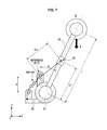
- FIG. 7 is a view showing positioning when rotation is performed on a plane parallel with a gravity direction.
- the first joint 21 may be rotated on a plane parallel with a gravity direction in accordance with the movement of the hip joint.
- the plane parallel with the gravity direction is indicated as the x-y plane.
- the first link 22 may form the angle ⁇ on the x-y plane with the reference axis of the fourth joint 35 .
- ⁇ may be defined as a rotation angle in a horizontal direction.
- Equation 1 M denotes a weight of the wearer including the weight of the walk-assistive apparatus, g denotes acceleration of gravity, l denotes a length of the first link, and ⁇ denotes a rotation angle in a horizontal direction.
- Equation 2 K denotes a spring constant, ⁇ s denotes a length of the spring connected to the reference axis of the fourth joint and the spring holder, r denotes a moment arm for the second joint by the spring, u denotes a distance between a position of the spring t and the center of the second joint on the reference axis of the fourth joint, and P 1 denotes a movement position of the spring holder from the center of the second joint.
- Equation 2 The position P 1 of the spring holder 25 in Equation 2 may be determined in accordance Equation 3.
- the movement position of the spring holder 25 may be determined by M (weight of the wearer including the weight of the walk-assistive apparatus), g (acceleration of gravity), l (length of the first link), K (spring constant), and u (distance between the position of the spring and the center of the second joint on the reference axis of the fourth joint) regardless of the rotation angle ⁇ in the horizontal direction.
- the torque (T) may not be required because by moving the spring and the spring holder 25 , the weight in the horizontal direction may be compensated to maintain the rotation angle ⁇ .
- FIGS. 8A and 8B are views showing positioning when rotation is performed on a plane not parallel with a gravity direction.
- the first joint 21 when the wearer walks while spreading his or her legs outwardly as well as lifting his or her legs in front and rear directions of the wearers, the first joint 21 may be rotated on a plane not parallel with the gravity direction in accordance with the movement of the hip joint.
- the plane not parallel with the gravity direction may continuously change in accordance with a spreading angle of the legs of the wearer, the plane on which the first joint 21 is rotated is fixed as an x-y′ plane in FIGS. 8A and 8B for convenience of the description.
- the first joint 21 viewed from the front side or rear side (x axis) of the wearer forms an angle ⁇ with the second waist support unit 14 that is the center axis of the rotation of the first joint 21 .
- the first link 22 viewed from the front or rear side (x axis) of the wearer may form the angle ⁇ with the second waist support unit 14 , that is, on the y axis and the y-z plane as shown in FIG. 8A .
- the first link 22 is rotated on a plane obtained by rotating the x-y plane with respect to the y axis by the angle ⁇ , and on a plane (hereinafter referred to as an x-y′ plane) formed by the x axis and a y′ axis.
- ⁇ may be defined as a rotation angle in a vertical direction.
- the first link 22 viewed from a direction perpendicular to the x-y′ plane is the same as shown in FIG. 8B .
- the drawing of FIG. 8B is similar to the drawing of FIG. 7 .
- acceleration for the mass M is changed to g ⁇ cos( ⁇ ) in FIG. 8B .
- Equation 3 may be modified to Equation 4 for determining a movement position P 2 of the spring holder 25 .
- P 2 P 1 ⁇ cos( ⁇ ), [Equation 4]
- the processor 120 may determine the movement position P 2 of the spring holder 25 in accordance with Equation 4, based on the rotation angle ⁇ in the vertical direction transmitted from the first measuring unit 210 a .
- the processor 120 may output control signals to the holder driving unit 220 so as to move the spring holder 25 to the determined position.
- the movement of the spring holder 25 may be facilitated using a worm gear, and detailed description thereof will be made with reference to FIGS. 9A and 9B .
- FIGS. 9A and 9B are views showing a structure of a spring holder and a peripheral structure of the spring holder.
- the spring holder 25 is linearly moved on the linear guide 26 , and moved close to or away from the center of the second joint 31
- the spring holder 25 includes a slot which penetrates the linear guide 26 in a vertical direction, and a position adjuster 27 for directly adjusting the movement position of the spring holder 25 using the slot and a worm gear 28 for adjusting rotation of the position adjuster 27 are provided in the periphery of the spring holder 25 .
- the position adjuster 27 may be divided into a first body formed into a fan shape and a second body formed into a gear shape, and the first body and the second body may be coupled.
- a portion which protrudes to be inserted into the slot of the spring holder 25 that is, a protrusion, is provided in the first body, and a bearing or a friction reducing member which is inserted into the slot to be smoothly moved inside the slot may be mounted outside of the protrusion.
- the second body formed into the gear shape is engaged with the gap of the worm gear 28 , and thereby is rotatable to the left and right in accordance with rotation of the worm gear 28 .
- the second body is rotated along with the rotation of the worm gear 28 , and therefore the protrusion provided in the first body may be positioned at the center of the slot of the spring holder 25 as shown in FIG. 9A .
- the second body may be rotated to the right along with the rotation of the worm gear 28 , and therefore the protrusion provided in the first body may be positioned at one end of the slot.
- Equation 5 a method of obtaining an angle ⁇ at which the position adjuster 27 is rotated from the determined movement position P 2 of the spring holder 25 may be performed using Equation 5.
- the processor 120 calculates the rotation angle ⁇ of the position adjuster 27 using the determined movement position P 2 of the spring holder 25 and Equation 5.
- the processor 120 calculates a rotating amount of the worm gear 28 corresponding to the calculated angle ⁇ using a gear ratio, and outputs control signals to the holder driving unit 230 so that the worm gear 28 is rotated by the calculated rotating amount.
- the position adjuster 27 is rotated by the angle ⁇ , and the spring holder 25 is moved to the determined position P 2 .
- the holder driving unit 230 may be implemented by a motor for generating a torque in accordance with electric energy supplied from a power source 110 or the like of the main body 10 in the same manner as in the joint driving unit 220 , and the holder driving unit 230 may be implemented by at least one piston or cylinder device which is operated by the electric energy supplied from the main body 10 or the like or a pressure of a fluid, for example, by pressure such as oil pressure or air pressure to thereby generate a torque.
- the holder driving unit 230 may be implemented to include at least one motor or include at least one piston or cylinder device.
- FIGS. 9A and 9B the movement of the spring holder 25 by the worm gear has been described, but example embodiments are not limited thereto.
- FIG. 10 is a flowchart showing a method of controlling a walk-assistive apparatus according to some example embodiments.
- the first measuring unit 210 a may measure a rotation angle of the first joint 21 .
- the wearer may lift his or her legs in left and right directions of the wearer as well as in front and rear directions of the wearer while walking. In other words, the wearer may walk while spreading his or her legs outward as well as lifting his or her legs in the front and rear directions of the wearer.
- the first joint 21 may form an angle ⁇ on the y-z plane with the second waist support unit 14 being a center axis of the rotation of the first joint 21 , that is, with the y axis.
- the first measuring unit 210 a measures the rotation angle ⁇ in the vertical direction of the first joint 21 .
- the processor 120 may determine a position to which the spring holder 25 is to be moved using the measured rotation angle.
- the processor 120 may determine a movement position P 2 of the spring holder 25 using Equation 4 discussed above.
- the processor 120 may instruct the holder driving unit 230 to move the spring holder 25 to the determined position.
- the processor 120 may calculates a rotation angle ⁇ of the position adjuster 27 using the determined movement position P 2 of the spring holder 25 and Equation 5 discussed above.
- the length of the spring may be increased or reduced, an elastic force may be obtained in accordance with the change in the length of the spring, and a state of the wearer lifting his or her legs may be maintained or assisted through weight compensation by the elastic force.
- a separate torque applied to the walk-assistive apparatus 1 for maintaining and assisting the state of lifting the wearer's legs may not be required, and energy supplied from the power source 110 in order to apply the torque may be reduced.
- the walk-assistive apparatus and the method of controlling the walk-assistive apparatus may use a mechanical element such as a spring to reduce energy, and weight compensation having uniform performance may be performed even in an arbitrary posture.
Landscapes
- Health & Medical Sciences (AREA)
- Veterinary Medicine (AREA)
- Life Sciences & Earth Sciences (AREA)
- Animal Behavior & Ethology (AREA)
- General Health & Medical Sciences (AREA)
- Public Health (AREA)
- Rehabilitation Therapy (AREA)
- Physical Education & Sports Medicine (AREA)
- Pain & Pain Management (AREA)
- Epidemiology (AREA)
- Heart & Thoracic Surgery (AREA)
- Biomedical Technology (AREA)
- Cardiology (AREA)
- Transplantation (AREA)
- Vascular Medicine (AREA)
- Oral & Maxillofacial Surgery (AREA)
- Engineering & Computer Science (AREA)
- Rehabilitation Tools (AREA)
Abstract
A walk-assistive apparatus may include at least one joint that corresponds to at least one joint of a wearer, at least one link that connects the joint, and is rotated in response to rotation of the joint, a spring that is mounted in the link or the joint so that a length of the spring is changed in accordance with rotation of the link or the joint, and a processor that controls the change in the length of the spring to compensate for a weight by gravity when the wearer walks. Accordingly, the walk-assistive apparatus and a method of controlling the walk-assistive apparatus may use a mechanical element such as a spring to reduce energy, and weight compensation having uniform performance may be performed even in an arbitrary posture.
Description
This application claims the benefit of Korean Patent Application No. 10-2014-0018504, filed on Feb. 18, 2014 in the Korean Intellectual Property Office, the entire disclosure of which is incorporated herein by reference.
1. Field
Example embodiments relate to a walk-assistive apparatus and a method of controlling the walk-assistive apparatus.
2. Description of the Related Art
A walk-assistive apparatus is a mechanism that may assist a wearer with a disability affecting their ability to walk so that the wearer can more easily walk. Walking may become uncomfortable for people due to innate reasons such as genetic defects or acquired reasons such as age, diseases, accidents, and the like, and walk-assistive apparatuses may relieve such discomfort in walking.
As such a walk-assistive apparatus, a walk-assistive car in which at least one wheel and a support are installed, a walk-assistive robot that assists a wearer with walking by applying a force required for walking to muscles of the human body, or the like may be used.
The walk-assistive robot may be fixed to the buttocks, the femoral region, the shanks, and the like of the human body, and assist movements of muscles and joints by applying a force such as a rotational force by an actuator or various other mechanical means. The wearer may walk more easily with the assistance of the walk-assistive robot.
Example embodiments are related to a walk-assistive apparatus and a method of controlling the walk-assistive apparatus. In at least some example embodiments, the walk-assistive apparatus may be configured to compensate for weight using a spring.
Additional aspects of the example embodiments will be set forth in part in the description which follows and, in part, will be obvious from the description, or may be learned by practice of the example embodiments.
In accordance with some example embodiments, the walk-assistive apparatus may include at least one joint that corresponds to at least one joint of a wearer; at least one link that connects the joint, and is rotated in response to rotation of the joint; a spring that is mounted in the link or the joint so that a length of the spring is changed in accordance with rotation of the link or the joint; and a processor that controls the change in the length of the spring to compensate for a weight by gravity when the wearer walks.
The joint may include a first joint and a second joint respectively corresponding to a hip joint and a knee joint of the wearer, and the link may include a first link that connects the first joint and the second joint and is rotated in response to rotation of the first joint.
Also, the joint may include a fourth joint that is provided around the second joint and rotated independently from the second joint.
Also, the walk-assistive apparatus may further include a reference bar that is fixed to the fourth joint to form a reference axis of the rotation of the fourth joint.
Also, the walk-assistive apparatus may further include a spring that is fixed at one end thereof to the fourth joint, and fixed at the other end thereof to a spring holder movably provided on the first link.
Also, the processor may control movement of the spring holder.
Also, the processor may determine a movement position of the spring holder, and controls the spring holder to be moved to the determined position.
Also, the first joint may be rotated in a front, rear, left, or right direction of the wearer in response to movement of the hip joint when the wearer walks.
Also, the fourth joint may be rotated to allow the reference bar to be maintained in a parallel state with a gravity direction.
Also, the walk-assistive apparatus may further include at least one string that connects the first joint and the fourth joint.
Also, a length of the at least one string wound around the first joint and the fourth joint may be adjusted so that the parallel state is maintained when the fourth joint is rotated.
Also, an intermediate end of the spring may be fixed to the reference bar.
Also, the processor may determine a movement position P2 of the spring holder using the Equation: P2=P1·cos(ζ), where
ζ denotes an angle at which the first joint is rotated to the left or right of the wearer in the gravity direction as a center axis, P1 denotes a position from a center of the second joint to the spring holder at an initial ζ=0, M denotes a weight of the wearer including a weight of the walk-assistive apparatus, g denotes the acceleration of gravity, l denotes a length of the first link, K denotes a spring constant, and u denotes a distance between a position of the spring fixed to the reference bar and the center of the second joint.
Also, the walk-assistive apparatus may further include a worm gear, wherein the processor controls the movement of the spring holder by driving the worm gear.
Also, the walk-assistive apparatus may further include a position adjuster that is rotated in accordance with driving of the worm gear to move the spring holder.
Also, the spring holder may include a slot, and the position adjuster may include a protrusion that is inserted into the slot.
Also, the protrusion may be moved inside the slot to move the spring holder when the position adjuster is rotated in accordance with the driving of the worm gear.
Also, the processor may determine a rotation angle α of the position adjuster using the Equation:
and control the driving of the worm gear so that the position adjuster is rotated by the determined angle α, where ζ denotes an angle at which the first joint is rotated to the left or right of the wearer in the gravity direction as a central axis, P2 denotes a determined movement position of the spring holder, P1 denotes a position to the spring holder from the center of the second joint at an initial ζ=0, C denotes a distance from the center of the second joint to a rotation center of the position adjuster, and R denotes a distance from a rotation center of the position adjuster to a center of the protrusion.
In other example embodiments, the method of controlling a walk-assistive apparatus may include rotating a first joint in a front, rear, left, or right direction of a wearer in response to movement of a hip joint of the wearer when the wearer walks; measuring a rotation angle of the first joint; determining a movement position of a spring holder from a second joint corresponding to a knee joint of the wearer based on the measured angle; and moving the spring holder to correspond to the determined position on a first link connecting the first joint and the second joint.
The rotating of the first joint may include rotating a fourth joint provided around the second joint and rotated independently from the second joint, in response to the rotation of the first joint.
Also, the rotating of the first joint may include rotating the fourth joint so that a reference bar fixed to the fourth joint is maintained in a parallel state with a gravity direction.
Also, the rotating of the first joint may include adjusting a length of at least one string wound around the first joint and the fourth joint, the at least one string connecting the first joint and the fourth joint, so that the parallel state is maintained.
Also, the moving of the spring holder may include changing a length of a spring that is fixed at one end thereof to the fourth joint, and fixed at the other end thereof to the spring holder.
Also, the moving of the spring holder may include changing a length from an intermediate end of the spring fixed to the reference bar to the other end of the spring fixed to the spring holder.
Also, the determining of the movement position of the spring holder may include determining the movement position P2 of the spring holder using the Equation: P2=P1·cos(ζ), where
ζ denotes an angle at which the first joint is rotated to the left or right of the wearer in the gravity direction as a center axis, P1 denotes a position from a center of the second joint to the spring holder at an initial ζ=0, M denotes a weight of the wearer including a weight of the walk-assistive apparatus, g denotes the acceleration of gravity, l denotes a length of the first link, K denotes a spring constant, and u denotes a distance between a position of the spring fixed to the reference bar and the center of the second joint.
Also, the moving of the spring holder may include controlling the movement of the spring holder by driving a worm gear.
Also, the moving of the spring holder may include moving the spring holder by rotating a position adjuster in accordance with the driving of the worm gear.
Also, the moving of the spring holder may include moving the spring holder by moving a protrusion provided in the position adjuster inside a slot provided in the spring holder when the position adjuster is rotated.
Also, the method of controlling a walk-assistive apparatus may further include determining a rotation angle α of the position adjuster using the Equation
where ζ denotes an angle at which the first joint is rotated to the left or right of the wearer in the gravity direction as a central axis, P2 denotes a determined movement position of the spring holder, P1 denotes a position to the spring holder from the center of the second joint at an initial ζ=0, C denotes a distance from the center of the second joint to a rotation center of the position adjuster, and R denotes a distance from a rotation center of the position adjuster to a center of the protrusion.
Also, the moving of the spring holder may include controlling driving of the worm gear so that the position adjuster is rotated by the determined angle α.
These and/or other aspects of the example embodiments will become apparent and more readily appreciated from the following description of the embodiments, taken in conjunction with the accompanying drawings of which:
Reference will now be made in detail to the example embodiments, some examples of which are illustrated in the accompanying drawings, wherein like reference numerals refer to like elements throughout.
Example embodiments will now be described more fully with reference to the accompanying drawings, in which some example embodiments are shown. In the drawings, the thicknesses of layers and regions are exaggerated for clarity. Like reference numerals in the drawings denote like elements.
Detailed illustrative embodiments are disclosed herein. However, specific structural and functional details disclosed herein are merely representative for purposes of describing example embodiments. Example embodiments may be embodied in many alternate forms and should not be construed as limited to only those set forth herein.
It should be understood, however, that there is no intent to limit this disclosure to the particular example embodiments disclosed. On the contrary, example embodiments are to cover all modifications, equivalents, and alternatives falling within the scope of the example embodiments. Like numbers refer to like elements throughout the description of the figures.
It will be understood that, although the terms first, second, etc. may be used herein to describe various elements, these elements should not be limited by these terms. These terms are only used to distinguish one element from another. For example, a first element could be termed a second element, and, similarly, a second element could be termed a first element, without departing from the scope of this disclosure. As used herein, the term “and/or,” includes any and all combinations of one or more of the associated listed items.
It will be understood that when an element is referred to as being “connected,” or “coupled,” to another element, it can be directly connected or coupled to the other element or intervening elements may be present. In contrast, when an element is referred to as being “directly connected,” or “directly coupled,” to another element, there are no intervening elements present. Other words used to describe the relationship between elements should be interpreted in a like fashion (e.g., “between,” versus “directly between,” “adjacent,” versus “directly adjacent,” etc.).
The terminology used herein is for the purpose of describing particular embodiments only and is not intended to be limiting. As used herein, the singular forms “a,” “an,” and “the,” are intended to include the plural forms as well, unless the context clearly indicates otherwise. It will be further understood that the terms “comprises,” “comprising,” “includes,” and/or “including,” when used herein, specify the presence of stated features, integers, steps, operations, elements, and/or components, but do not preclude the presence or addition of one or more other features, integers, steps, operations, elements, components, and/or groups thereof.
It should also be noted that in some alternative implementations, the functions/acts noted may occur out of the order noted in the figures. For example, two figures shown in succession may in fact be executed substantially concurrently or may sometimes be executed in the reverse order, depending upon the functionality/acts involved.
Various example embodiments will now be described more fully with reference to the accompanying drawings in which some example embodiments are shown. In the drawings, the thicknesses of layers and regions are exaggerated for clarity.
As shown in FIGS. 1 and 2 , the walk-assistive apparatus 1 may have an exoskeleton structure of a joint system similar to the human body. Further, as discussed below with reference to FIG. 3 , the walk-assistive apparatus 1 may include a walk-assistive unit 2 that is worn on the whole or a part of a lower limb of a wearer so as to assist the wearer with walking and a main body 10 that controls the walk-assistive unit 2 or collects a variety of information.
The walk-assistive unit 2 may include at least one of a first structure unit 20, a second structure unit 30, and a third structure unit 40 as shown in FIGS. 1 and 2 .
Hereinafter, a case in which the walk-assistive apparatus 1 includes all of the first structure unit 20, the second structure unit 30, and the third structure unit 40 will be described, however, example embodiments are not limited thereto.
Further, the walk-assistive unit 2 may include a single first structure unit 20, a single second structure unit 30, and a single third structure unit 40. In this instance, the first structure unit 20, the second structure unit 30, and the third structure unit 40 may be worn on at least one of the left leg and the right leg of the wearer. Also, as shown in FIG. 1 , the walk-assistive unit 2 may include a pair of the first structure units 20 and 20 a, a pair of the second structure units 30 and 30 a, and a pair of the third structure units 40 and 40 a so that the walk-assistive unit 2 can be worn on the left leg and the right leg of the wearer. When the walk-assistive unit 2 includes the pair of first structure units 20, the pair of second structure units 30, and the pair of third structure units 40, functions and operations of the respective structure units 20, 30 and 40 are substantially the same. The walk-assistive unit 2 may include one of some of the plurality of structure units 20, 30 and 40 and pairs of the other structure units. For example, the walk-assistive unit 2 may include one pair of the first structure units 20 and 20 a, one second structure unit 30 and one third structure unit 40.
Hereinafter, the single first to third structure units 20, 30 and 40 will be described, but the corresponding descriptions may be equally applied to pairs of the respective structure units.
The first structure unit 20 may assist movements of the femoral region and the hip joint of the wearer when the wearer walks. The first structure unit 20 may include at least one first joint 21 and at least one first link 22.
The first joint 21 is a part corresponding to the hip joint of the human body and is provided in a connection region of a second waist support unit 14 and the first link 22. As discussed below in more detail with reference to FIG. 3 , the first joint 21 may receive a torque from a joint driving unit 220 configured to rotate in various directions and angles.
Example embodiments may have at least one degree of freedom (DOF) for rotation of the first joint 21. Here, DOF refers to DOF in forward kinematics or inverse kinematics, and means an independent parameter required for representing a position of an object. For example, an object in a three-dimensional space having x, y, and z axes has three DOFs (that is, a position on each axis) for determining a spatial position of the object and three DOFs for determining a spatial orientation of the object. That is, when it is assumed that an object is movable along each axis and rotatable with respect to each axis, it can be understood that the object has six DOFs.
The first link 22 serves to support the femoral region of the wearer. The first link 22 may be formed in various shapes, as necessary, and, for example, may have a bar shape as shown in FIGS. 1 and 2 . A length of the first link 22 may be adjustable. Thus, the wearer may adjust the length of the first link 22 to match the length of his or her own femoral region before or while wearing the walk-assistive apparatus 1.
An end of the first link 22 is connected to the first joint 21 to be rotated in accordance with rotation of the first joint 21. A range of the rotation of the first joint 21 may be within an operation range of the hip joint of the wearer. Also, a first fixing unit 23 for fixing the first link 22 to the femoral region of the wearer may be provided in an inner side or an outer side of the first link 22. Thus, when the first link 22 is rotated, the femoral region of the wearer fixed to the first link 22 by the first fixing unit 23 may be rotated in the same direction as the first link 22.
For example, as the first joint 21 is rotated in front and rear directions of the wearer, the first link 22 is rotated by drawing a circular arc on a plane (hereinafter referred to as an “x-y plane”) formed by the x and y axes with respect to the first joint 21. In addition, the femoral region of the wearer may be rotated on the x-y plane with respect to the first joint 21 in the same direction as the rotation direction of the first link 22. As another example, as the first joint 21 is rotated in left and right directions of the wearer, the first link 22 is rotated by drawing a circular arc on a plane (hereinafter referred to as a “y-z plane”) formed by the y and z axes with respect to the first joint 21. In addition, the femoral region of the wearer may be rotated on the y-z plane with respect to the first joint 21 in the same direction as the rotation direction of the first link 22.
In other words, the first joint 21 and the first link 22 are rotated by the torque applied from the joint driving unit 220, and therefore the wearer may be assisted by assist power provided from the walk-assistive apparatus 1 when walking or raising his or her leg.
Meanwhile, the first fixing unit 23 may be made of a metal material, an elastic material such as rubber and the like. The first fixing unit 23 may be implemented in the form of a chain as shown in FIG. 1 , in the form of a band with elasticity, or in the form of a strap, however example embodiments are not limited thereto. For example, various fixing means which can be considered by those skilled in the art in order to fix the first link 22 to the femoral region or the like may be included in an example of the first fixing unit 23.
The second structure unit 30 may assist movements of the lower thigh region and the knee joint of the wearer when the wearer walks. The second structure unit 30 may include at least one second joint 31 and at least one second link 32.
The second joint 31 is a part corresponding to the knee joint of the human body, and is provided in a connection region of the first link 22 and the second link 32. As discussed below in more detail with reference to FIG. 3 , the second joint 31 may receive a torque from the joint driving unit 220 that is configured to rotate in various directions and angles, and may have at least one DOF.
The second link 32 serves to support the lower thigh region of the wearer. The second link 32 may be formed into various shapes, as necessary, and may have the same bar shape as the first link 22 as shown in FIGS. 1 and 2 . However, a thickness and a size of the second link 32 may be different from those of the first link 22, and may be formed into a different shape, as necessary. Also, a length of the second link 32 may be adjustable in the same manner as the first link 22. Thus, the wearer may adjust the length of the first link 22 to match his or her own lower thigh region before or while wearing the walk-assistive apparatus 1.
An end of the second link 32 is connected to the second joint 31 to be rotated along rotation of the second joint 31, and at least one second fixing unit 33 and 34 for fixing the second link 32 to the lower thigh region of the wearer may be provided in an inner side or an outer side of the second link 32. Thus, when the second link 32 is rotated, the lower thigh region of the wearer fixed to the second link 32 by the second fixing units 33 and 34 may be rotated in the same direction as the second link 32.
For example, as the second joint 31 is rotated in front and rear directions of the wearer, the second link 32 is rotated with respect to the second joint 31 by drawing a circular arc on the x-y plane. In addition, the lower thigh region of the wearer may be rotated on the x-y plane with respect to the second joint 31 in the same direction as the rotation direction of the second link 32. As another example, as the second joint is rotated in left and right directions of the wearer, the second link 32 is rotated with respect to the second joint 31 by drawing a circular arc on the y plane. In addition, the lower thigh region of the wearer may be rotated on the y-z plane with respect to the second joint 31 in the same direction as the rotation direction of the second link 32.
In other words, the second joint 31 and the second link 32 may be rotated by the torque applied from the joint driving unit 220, and such a structure of the second structure unit 30 assists movements of the lower thigh region and the knee joint of the wearer. Thus, the wearer may be assisted by assist power provided from the walk-assistive apparatus 1 when walking or raising his or her leg.
Meanwhile, configurations, structures, materials, and the like of the second fixing units 33 and 34 may be the same as those of the first fixing unit 23.
The third structure unit 40 may assist operations of ankles of the wearer when the wearer walks. The third structure unit 40 may include at least one third joint 41 and a foot rest unit 42.
The third joint 41 is a part corresponding to the ankle joint of the human body, and is provided in the connection region of the second link 32 and the foot rest unit 42. The third joint 41 may also receive a torque from the joint driving unit 220 configured to rotate in various directions and angles, and may have one DOF.
The foot rest unit 42 is a part for supporting soles of the wearer, and includes a third fixing unit 43 to mutually fix the foot of the wearer seated on the foot rest unit 42 and the foot rest unit 42. The configuration, the structure, the material, and the like of the third fixing unit 43 may be the same as those of the first fixing unit 23 or the second fixing units 33 and 34.
The main body 10 may control operations of the walk-assistive apparatus 1 or acquire information related to the walking. In addition, the main body 10 supports an upper body of the wearer to assist the wearer in stably wearing the walk-assistive apparatus 1.
The main body 10 may include at least one of a housing 10 a and an input unit.
In the housing 10 a, a printed circuit board in which various processing devices such as a central processing unit (CPU), a graphic processing unit (GPU), and the like and a semiconductor chip can be installed, and various kinds of storage devices may also be in the housing 10 a, as necessary.
As discussed in more detail below in regard to FIG. 3 , in the housing 10 a, a processor 120 may be provided to generate control signals for controlling the walk-assistive unit 2. In addition, the generated control signals may be transmitted to the walk-assistive unit 2 through wired or wireless communication.
The housing 10 a may stably fix various components while safely protecting the various components.
In the main body 10, an input unit (not shown) capable of inputting a variety of information for operations of the walk-assistive apparatus 1 or operating various devices may be provided, thereby providing a user interface (UI).
The main body 10 may further include a first waist support unit 13, a second waist support unit 14, a first waist fixing unit 11, and a second waist fixing unit 12.
The first waist support unit 13 and the second waist support unit 14 serve to support the waist of the wearer. For this, an end of the second waist support unit 14 is connected to the first joint 21, and other end thereof is connected to the first waist support unit 13. The first waist support unit 13 may be designed as a curved flat plate to conform to a waist shape.
The first waist fixing unit 11 may fix the first waist support unit 13 to the waist of the wearer, and the second waist fixing unit 12 may fix the housing 10 a to the waist or buttocks of the wearer. The first waist fixing unit 11 and the second waist fixing unit 12 may be made of a metal material or an elastic material such as rubber. The first waist fixing unit 11 and the second waist fixing unit 12 may be provided in the form of a chain, a band with elasticity, or various kinds of straps. Other than these, the first waist fixing unit 11 and the second waist fixing unit 12 may include various fixing means which can be considered by those skilled in the art in order to fix the first waist support unit 13 or the housing 10 a to the waist, the buttocks, or the like.
The walk-assistive apparatus 1 may include at least one detection unit 200, at least one measuring unit 210, at least one joint driving unit 220, a holder driving unit 230, a power source 110, and the processor 120 to assist the wearer's movements when the wearer walks or lifts or lowers his or her legs.
In some example embodiments, as shown in FIG. 3 , the at least one detection unit 200, the at least one measuring unit 210, the at least one joint driving unit 220, and the holder driving unit 230 may be included in the walk-assistive unit 2, and the power source 110 and the processor 120 may be included in the main body 10, however, example embodiments are not limited thereto.
The at least one joint driving unit 220 may include a first joint driving unit 220 a for driving the first joint 21, a second joint driving unit 220 b for driving the second joint 31, and a third joint driving unit 220 c for driving the third joint 41.
The joint driving unit 220 may generate torques having various sizes in accordance with control signals from the processor 120, and apply the generated torques to the respective joints 21, 31, and 41 to enable the respective joints 21, 31, and 41 to be rotated in various directions and angles.
The joint driving unit 220 may be implemented by a motor that generates a torque in accordance with electric energy supplied from the power source 110 of the main body 10 or the like. In this instance, the motor may be a motor including an encoder. In addition, the joint driving unit 220 may be implemented as at least one piston or cylinder device that is operated by the electric energy supplied from the main body 10 or the like or a pressure of a fluid, for example, by pressure such as oil pressure or air pressure to thereby generate a torque. The joint driving unit 220 may be implemented to include at least one motor or include at least one piston and at least one cylinder device.
The at least one detection unit 200 may be divided into a first detection unit 200 a included in the first structure unit 20, a second detection unit 200 b included in the second structure unit 30, and a third detection unit 200 c included in the third structure unit 40. In addition, the at least one measuring unit 210 may also be divided into a first measuring unit 210 a included in the first structure unit 20, a second measuring unit 210 b included in the second structure unit 30, a third measuring unit 210 c included in the third structure unit 40.
The first detection unit 200 a may detect at least one operation of movements of the first joint 21, the first link 22, and the wearer's hip joint. The first detection unit 200 a may generate electrical signals in response to the detected movement, thereby acquiring information related to walking. The information related to the walking may include at least one of a joint angle, an inclination of the first link 22, an angular speed of the joint, and an acceleration of the joint. The information obtained in the first detection unit 200 a may be transmitted to the processor 120.
The first detection unit 200 a may include at least one of, for example, a joint angle sensor, an inclination sensor, an acceleration sensor, and an inertial measurement unit (IMU). The first detection unit 200 a may be installed in at least one of the first joint 21 and the first link 22. According to some example embodiments, the first detection unit 200 a may be installed in both of the first joint 21 and the first link 22. In other example embodiments, a part of the first detection unit 200 a may be installed in the first joint 21 and the other part may be installed in the first link 22. For example, the joint angle sensor may be installed in the first joint 21, and the inclination sensor or IMU may be installed in the first link 22.
The first measuring unit 210 a is connected to the first joint 21 to obtain information related to movements of the first joint 21. The information related to the movement of the first joint 21 may include at least one of a rotation angle, an angle speed, and an angle acceleration. The first measuring unit 210 a may measure a joint angle, a speed, and an acceleration using an encoder value when the first joint driving unit 220 a is a motor with the encoder. A parameter measured in the first measuring unit 210 a may be transmitted to the processor 120.
The second detection unit 200 b may detect at least one of the movements of the second joint 31, the second link 32, and the wearer's knee joint to convert the detected movement to electrical signals, and transmit the electrical signals to the processor 120. The second detection unit 200 b may include at least one of the joint angle sensor, the inclination sensor, the acceleration sensor, and the IMU. The second detection unit 200 b may be installed in at least one of the second joint 31 and the second link 32. In the same manner as the first detection unit 200 a, a part of the second detection unit 200 b may be installed in the second joint 31, and the other part thereof may be installed in the second link 32.
The second measuring unit 210 b may obtain information related to the movement of the second joint 31. The information related to the movement of the second joint 31 may include at least one of a rotation angle, an angle speed, and an angle acceleration. When the second joint driving unit 220 b is a motor with the encoder, the second measuring unit 210 b may measure a joint angle, a speed, and an acceleration using an encoder value. A parameter measured in the second measuring unit 210 b may be transmitted to the processor 120.
The third detection unit 200 c may detect at least one of movements of the third joint 41, the foot rest unit 42, and the wearer's ankle joint. The third detection unit 200 c may include at least one of a joint angle sensor, an inclination sensor, an acceleration sensor, and an IMU. In some example embodiments, the third detection unit 200 c may include a pressure sensor. The pressure sensor may be installed in the foot rest unit 42, and may detect whether the wearer wears the walk-assistive apparatus 1 or whether the wearer stands up by detecting the wearer's weight. The pressure sensor may be a ground reaction force sensor that may detect a ground reaction force (GRF) transmitted to the wearer's foot. Signals generated in accordance with detection by the third detection unit 200 c may be transmitted to the processor 120.
The third measuring unit 210 c may measure information related to movements of the third joint 41, and may transmit the measured information to the processor 120. When the third joint driving unit 220 c is a motor with the encoder, the third measuring unit 210 c may measure a joint angle, a speed, and an angle acceleration using an encoder value.
The power source 110 may supply power to various components within the housing 10 a or components such as the respective joints 21, 31, and 41 of the walk-assistive unit 2. The power source 110 may be built in the housing 10 a, or separately provided outside the housing 10 a.
In addition, the power source 110 may be a primary battery, or a secondary battery. When the power source 110 is a primary battery, the power source 110 may include a mercury battery, a manganese battery, an alkaline battery, a lithium battery, or the like. When the power source 110 is a secondary battery, the power source 110 may include a nickel-cadmium (Ni—Cd) battery, a nickel-metal hydride (Ni—NH) battery, a lead acid battery, a lithium ion (Li-ion) battery, a lithium polymer battery, or the like.
In addition to the processor 120, the main body 10 may also include a memory (not shown).
The processor 120 may be implemented by at least one semiconductor chip disposed on a printed circuit board built in the housing 10 a. The processor may be an arithmetic logic unit, a digital signal processor, a microcomputer, a field programmable array, a programmable logic unit, a microprocessor or any other device capable of responding to and executing instructions in a defined manner such that the processor is programmed with instructions that configure the processor 120 as a special purpose computer to perform the operations illustrated in FIG. 10 , such that the processor is configured to determine an amount of tension to apply to the second joint 32 to maintain a rotation angle θ between the first joint 21 and the waist of the wearer using a spring such that the spring compensates for a weight of the wearer.
Therefore, the walk-assistive apparatus 1 may compensate for the weight of the wearer to maintain the rotation angle θ of the first joint 21 without applying a separate torque (T) thereto.
The processor 120 may determine operation states of the hip joint, the knee joint, and the ankle joint or states of the joints 21, 31, and 41 corresponding to each joint based on information transmitted from the detection unit 200 and the measuring unit 210. In addition, the processor 120 may generate control signals for controlling the walk-assistive apparatus 1 based on the determined states of the hip joint, the knee joint, and the ankle joint or the joints 21, 31, and 41 corresponding to each joint.
The memory may be a non-volatile memory, a volatile memory, a hard disk, an optical disk, and a combination of two or more of the above-mentioned devices. The memory may be a non-transitory computer readable medium. The non-transitory computer-readable media may also be a distributed network, so that the program instructions are stored and executed in a distributed fashion. The non-volatile memory may be a Read Only Memory (ROM), a Programmable Read Only Memory (PROM), an Erasable Programmable Read Only Memory (EPROM), or a flash memory. The volatile memory may be a Random Access Memory (RAM).
As shown in FIG. 4 , walking may be divided into eight stages (s1 to s8).
In the first stage (s1) of walking, the right leg may be in a loading response (LR) state, and the left leg may be in a pre-swing (PSw) state. During transition from the eighth stage (s8) of walking to the first stage (s1) of walking, the heel of the right foot may touch the ground as shown in FIGS. 4 and 5 . On the other hand, toes of the left foot may touch the ground and the heel of the left foot may be separated from the ground (s8 to s1).
In the second stage (s2) of walking, the right leg may be in a mid stance (MSt) state, and the left leg is in an initial swing (ISw) state. During transition from the first stage (s1) to the second stage (s2), the toes and heel of the right foot may simultaneously touch the ground, and the left leg may start a swing operation. The heel of the left foot may be first separated from the ground, and the toes of the left foot may be separated from the ground after the heel of the left foot is separated from the ground (s1 to s2).
In the third stage (s3) of walking, the right leg may still be in the mid stance state, and the left leg may be in a mid swing (MSw) state. During transition from the second stage (s2) to the third stage (s3), the toes and heel of the right foot may all touch the ground, and the left leg may continuously perform a swing operation. The right foot and the left foot may be positioned adjacent to each other (s2 to s3).
In the fourth stage (s4) of walking, the right leg may be in a terminal stance (TSt) state, and the left leg may be in a terminal swing (TSw) state. During transition from the third stage (s3) to the fourth stage (s4), the heel of the right foot may start to be separated from the ground. On the other hand, the toes of the right foot may still touch the ground. Meanwhile, the left foot may maintain a state of not touching the ground (s3 to s4).
In the fifth stage (s5) of walking, the left leg may be in the loading response (LR) state and the right leg may be in the pre-swing (PSw) state, opposite to the first stage (s1) of walking.
During transition from the fourth stage (s4) to the fifth stage (s5), the heel of the left foot may touch the ground. Meanwhile, the toes of the right foot may touch the ground and the heel of the right foot may be separated from the ground (s4 to s5).
In the sixth stage (s6) of walking, the left leg may be in the mid stance (MSt) state, and the right leg may be in the initial swing (ISw) state. During transition from the fifth stage (s5) to the sixth stage (s6), the toes and heel of the left foot may simultaneously touch the ground. The right leg may start to perform a swing operation while the toes of the right foot are separated from the ground (s5 to s6).
In the seventh stage (s7) of walking, the left leg may still be in the mid stance state, and the right leg may be in the mid swing (MSw) state. During transition from the sixth stage (s6) to the seventh stage (s7), the toes and heel of the left foot may all touch the ground, and the right leg may continuously perform the swing operation (s6 to s7).
In the eighth stage (s8) of walking, the left leg may be in the terminal stance (TSt) state, and the left leg may be in the initial swing (ISw) state. During transition from the seventh stage (s7) to the eighth stage (s8), the right foot may maintain a state of still not touching the ground, and the heel of the left foot may start to be separated from the ground (s7 to s8).
The above-described first to eighth stages (s1 to s8) may be continuously repeated during walking.
The detection unit 200 may detect information related to operations of at least one joint when transition (s8 to s1 and s7 to s8) of the walking stage during walking is performed. Signals generated in accordance with detection of the detection unit 200 may be transmitted to the processor 120, and/or temporarily or non-temporarily stored in a storage device, such as the memory, and then transmitted to the processor 120.
The processor 120 may output control signals to the joint driving unit 220 based on the information transmitted from the detection unit 200. For example, the processor 120 may determine operation states of the hip joint, the knee joint, and the ankle joint based on the information transmitted from the detection unit 200, and outputs control signals to the joint driving unit 220 to assist the determined operation states.
A torque may be generated in the joint driving unit 220 in accordance with the control signals, and each of joints 21, 31, and 41 may receive the corresponding torque to rotate the joints 21, 31 and 41.
The measuring unit 210 may measure information related to operations of the respective joints 21, 31, and 41 when the respective joints 21, 31, and 41 are rotated in accordance with control of the processor 120 in a case in which transition (s8 to s1 and s7 and s8) of the walking stage during walking is performed. The information measured in the measuring unit 210 may be transmitted to the processor 120, and/or temporarily or non-temporarily stored in a storage device and then transmitted to the processor 120.
For example, a rotation angle of the first joint 21 measured from the first measuring unit 210 a may be transmitted to the processor 120.
The processor 120 may output the control signals to the holder driving unit 230 based on the information transmitted from the measuring unit 210.
For example, as discussed in more detail with regard to FIG. 6 , in some example embodiments, in order to compensate for a weight of the wearer and a weight of the link, the processor 120 may output the control signals to the holder driving unit 220 based on the rotation angle transmitted from the first measuring unit 210 a.
Referring to FIG. 6 , a fourth joint 35 may be provided at a periphery of the second joint 31. The fourth joint 35 may be an auxiliary joint that is separately rotatable without constraint on rotation of the second joint 31. The fourth joint 35 is connected with the first joint 21 by a first wire T1 and a second wire T2, and controlled by the first wire T1 and the second wire T2. In other words, the fourth joint 35 is rotatable independently from the second joint 31, but is controlled in such a manner that a reference axis of the fourth joint 35 maintains a parallel state on the x-y plane with the second waist support unit 14 that is a center axis of rotation of the first joint 21 by the first wire T1 and the second wire T2.
For example, a length of each of the first wire T1 and the second wire T2 which are wound around the first joint 21 and the fourth joint 35 may be changed in accordance with the rotation of the first joint 21. For example, when the first joint 21 is rotated in a front direction of the wearer, the length of the first wire T1 wound around the first joint 21 may increase and the length of the second wire T2 may be reduced, whereas the length of the first wire T1 wound around the fourth joint 35 is reduced and the length of the second wire T2 is increased.
In this manner, the lengths of the first wire T1 and the second wire T2 wound around the first joint 21 and the fourth joint 35 may change differently from each other, and therefore the reference axis of the fourth joint 35 may be controlled so as to maintain a parallel state on the x-y plane with the second waist support unit 14 that is a center axis of rotation of the first joint 21. That is, the fourth joint 35 is controlled so that the reference axis of the fourth joint 35 projected onto the x-y plane can achieve a vertical relationship with the ground, that is, a vertical relationship with the y axis.
A spring may be provided in the fourth joint 35, an end of the spring may be connected and fixed to the fourth joint 35, and the other end thereof may be movably connected to the first link 22 via the reference axis of the fourth joint 35. For example, a linear guide 26 may be provided in a longitudinal direction of the first link 22, and the other end of the spring is fixed to a spring holder 25.
The spring holder 25 may linearly move on the first link 22 through the linear guide 26. As the spring holder 25 is linearly moved, a length of the spring is increased or reduced, and therefore the walk-assistive apparatus 1 may obtain an elastic force by a spring constant.
The processor 120 may output the control signals to the holder driving unit 220 for movement of the spring holder 25.
The processor 120 may determine a movement position of the spring holder 25 based on the rotation angle transmitted from the first measuring unit 210 a. Hereinafter, positioning of the spring holder 25 by the processor 120 will be described with reference to FIGS. 7 to 8A .
When the wearer lifts his or her toes, heel, and soles, for example, when the wearer walks while lifting the leg only in front and rear directions of the wearer, the first joint 21 may be rotated on a plane parallel with a gravity direction in accordance with the movement of the hip joint.
In FIG. 7 , the plane parallel with the gravity direction is indicated as the x-y plane.
When it is assumed that the first link 22 forms an angle θ on the x-y plane with the second waist support unit 14 that is a center axis of the rotation of the first joint 21, the first link 22 may form the angle θ on the x-y plane with the reference axis of the fourth joint 35. As described above, this is because the reference axis of the fourth joint 35 maintains a parallel state on the x-y plane with the second waist support unit 14 that is the center axis of the rotation of the first joint 21. In this instance, θ may be defined as a rotation angle in a horizontal direction.
When it is assumed that M is a weight of the wearer including the weight of the walk-assistive apparatus 1, a torque (T) applied to the second joint to maintain the angle θ may be represented as the following Equation 1.
T=Mgl·sin(θ) [Equation 1]
T=Mgl·sin(θ) [Equation 1]
In Equation 1, M denotes a weight of the wearer including the weight of the walk-assistive apparatus, g denotes acceleration of gravity, l denotes a length of the first link, and θ denotes a rotation angle in a horizontal direction.
When the elastic force and the torque are kept in a static parallel state in order to replace the torque (T) with an elastic force by the spring, Equation 2 is obtained.
K·Δs·r=Mgl·sin(θ),
where
½r·Δs=½u·P 1·sin(θ) [Equation 2]
K·Δs·r=Mgl·sin(θ),
where
½r·Δs=½u·P 1·sin(θ) [Equation 2]
In Equation 2, K denotes a spring constant, Δs denotes a length of the spring connected to the reference axis of the fourth joint and the spring holder, r denotes a moment arm for the second joint by the spring, u denotes a distance between a position of the spring t and the center of the second joint on the reference axis of the fourth joint, and P1 denotes a movement position of the spring holder from the center of the second joint.
The position P1 of the spring holder 25 in Equation 2 may be determined in accordance Equation 3.
Specifically, when the first joint 21 and the first link 22 are rotated on a plane parallel with a gravity direction, the movement position of the spring holder 25 may be determined by M (weight of the wearer including the weight of the walk-assistive apparatus), g (acceleration of gravity), l (length of the first link), K (spring constant), and u (distance between the position of the spring and the center of the second joint on the reference axis of the fourth joint) regardless of the rotation angle θ in the horizontal direction.
As shown in Equation 3, when the movement position of the spring holder 25 is determined and the spring holder 25 is moved to the determined position, the torque (T) which should be applied to the second joint 31 in order to maintain the angle θ may not be required.
The torque (T) may not be required because by moving the spring and the spring holder 25, the weight in the horizontal direction may be compensated to maintain the rotation angle θ.
A case in which the wearer lifts his or her legs only in the front and rear directions has been described with reference to FIG. 7 . However, the wearer may lift his legs in left and right directions during walking as well as in front and rear directions, and in this case, a method of determining the movement position of the spring holder 25 may be different.
Referring to FIGS. 8A and 8B , when the wearer walks while spreading his or her legs outwardly as well as lifting his or her legs in front and rear directions of the wearers, the first joint 21 may be rotated on a plane not parallel with the gravity direction in accordance with the movement of the hip joint. Although the plane not parallel with the gravity direction may continuously change in accordance with a spreading angle of the legs of the wearer, the plane on which the first joint 21 is rotated is fixed as an x-y′ plane in FIGS. 8A and 8B for convenience of the description.
Specifically, when the wearer walks while spreading his legs outwardly by an angle ζ, the first joint 21 viewed from the front side or rear side (x axis) of the wearer forms an angle ζ with the second waist support unit 14 that is the center axis of the rotation of the first joint 21.
Thus, the first link 22 viewed from the front or rear side (x axis) of the wearer may form the angle ζ with the second waist support unit 14, that is, on the y axis and the y-z plane as shown in FIG. 8A . In other words, the first link 22 is rotated on a plane obtained by rotating the x-y plane with respect to the y axis by the angle ζ, and on a plane (hereinafter referred to as an x-y′ plane) formed by the x axis and a y′ axis. In this instance, ζ may be defined as a rotation angle in a vertical direction.
Thus, the first link 22 viewed from a direction perpendicular to the x-y′ plane is the same as shown in FIG. 8B . The drawing of FIG. 8B is similar to the drawing of FIG. 7 . However, since the x-y′ plane is obtained by rotating the x-y plane by ζ with respect to the y axis, acceleration for the mass M is changed to g·cos(ζ) in FIG. 8B .
Equation 3 may be modified to Equation 4 for determining a movement position P2 of the spring holder 25.
P 2 =P 1·cos(ζ), [Equation 4]
P 2 =P 1·cos(ζ), [Equation 4]
where
In Equation 4, P1 denotes a position from a center of the second joint 31 to the spring holder 25 at an initial ζ=0, M denotes a weight of the wearer including a weight of the walk-assistive apparatus, g denotes the acceleration of gravity, l denotes a length of the first link, K denotes a spring constant, and u denotes a distance between a position of the spring fixed to the reference bar of the fourth joint and the center of the second joint.
The processor 120 may determine the movement position P2 of the spring holder 25 in accordance with Equation 4, based on the rotation angle ζ in the vertical direction transmitted from the first measuring unit 210 a. The processor 120 may output control signals to the holder driving unit 220 so as to move the spring holder 25 to the determined position.
The movement of the spring holder 25 may be facilitated using a worm gear, and detailed description thereof will be made with reference to FIGS. 9A and 9B .
Referring to FIGS. 9A and 9B , the spring holder 25 is linearly moved on the linear guide 26, and moved close to or away from the center of the second joint 31
The spring holder 25 includes a slot which penetrates the linear guide 26 in a vertical direction, and a position adjuster 27 for directly adjusting the movement position of the spring holder 25 using the slot and a worm gear 28 for adjusting rotation of the position adjuster 27 are provided in the periphery of the spring holder 25.
The position adjuster 27 may be divided into a first body formed into a fan shape and a second body formed into a gear shape, and the first body and the second body may be coupled. A portion which protrudes to be inserted into the slot of the spring holder 25, that is, a protrusion, is provided in the first body, and a bearing or a friction reducing member which is inserted into the slot to be smoothly moved inside the slot may be mounted outside of the protrusion.
The second body formed into the gear shape is engaged with the gap of the worm gear 28, and thereby is rotatable to the left and right in accordance with rotation of the worm gear 28.
The second body is rotated along with the rotation of the worm gear 28, and therefore the protrusion provided in the first body may be positioned at the center of the slot of the spring holder 25 as shown in FIG. 9A . The second body may be rotated to the right along with the rotation of the worm gear 28, and therefore the protrusion provided in the first body may be positioned at one end of the slot.
As can be seen from FIGS. 9A and 9B , when the protrusion is positioned at the center portion of the slot, a distance from the center of the second joint 31 to the spring holder 25, that is, the movement position of the spring holder 25, is the farthest from the second joint 31. Likewise, when the protrusion is moved to either ends of the slots, the movement position of the spring holder 25 gradually comes closer to the second joint 31. When the protrusion is positioned at the ends of the slots, the movement position of the spring holder 25 is the closest. That is, a position of the protrusion within the slot is adjusted by the rotation of the worm gear 28, and therefore the movement position of the spring holder 25 from the center of the second joint 31 may be adjusted.
Meanwhile, a method of obtaining an angle α at which the position adjuster 27 is rotated from the determined movement position P2 of the spring holder 25 may be performed using Equation 5.
In Equation 5, P2 denotes a movement position of the spring holder 25 with respect to rotation ζ in the vertical direction, P1 denotes a position to the spring holder 25 from the center of the second joint 31 at an initial ζ=0, C denotes a distance from the center of the second joint 31 to a rotation center of the position adjuster, and R denotes a distance from a rotation center of the position adjuster to a center of the protrusion.
When the spring holder 25 and the peripheral structure of the spring holder 25 are the same as above, the processor 120 calculates the rotation angle α of the position adjuster 27 using the determined movement position P2 of the spring holder 25 and Equation 5.
The processor 120 calculates a rotating amount of the worm gear 28 corresponding to the calculated angle α using a gear ratio, and outputs control signals to the holder driving unit 230 so that the worm gear 28 is rotated by the calculated rotating amount. Thus, the position adjuster 27 is rotated by the angle α, and the spring holder 25 is moved to the determined position P2.
The holder driving unit 230 may be implemented by a motor for generating a torque in accordance with electric energy supplied from a power source 110 or the like of the main body 10 in the same manner as in the joint driving unit 220, and the holder driving unit 230 may be implemented by at least one piston or cylinder device which is operated by the electric energy supplied from the main body 10 or the like or a pressure of a fluid, for example, by pressure such as oil pressure or air pressure to thereby generate a torque. The holder driving unit 230 may be implemented to include at least one motor or include at least one piston or cylinder device.
In FIGS. 9A and 9B , the movement of the spring holder 25 by the worm gear has been described, but example embodiments are not limited thereto.
As above, the components of the walk-assistive apparatus 1 and the operations of the components thereof have been described, and now a method of controlling the walk-assistive apparatus 1 will be described herein with reference to a given flowchart.
Referring to FIG. 10 , in operation 500, the first measuring unit 210 a may measure a rotation angle of the first joint 21.
The wearer may lift his or her legs in left and right directions of the wearer as well as in front and rear directions of the wearer while walking. In other words, the wearer may walk while spreading his or her legs outward as well as lifting his or her legs in the front and rear directions of the wearer. When the wearer walks while spreading his or her legs outward by an angle ζ, the first joint 21 may form an angle ζ on the y-z plane with the second waist support unit 14 being a center axis of the rotation of the first joint 21, that is, with the y axis. The first measuring unit 210 a measures the rotation angle ζ in the vertical direction of the first joint 21.
In operation 510, the processor 120 may determine a position to which the spring holder 25 is to be moved using the measured rotation angle.
For example, based on the rotation angle ζ in the vertical direction measured by the first measuring unit 210 a, the processor 120 may determine a movement position P2 of the spring holder 25 using Equation 4 discussed above.
In operation 530, the processor 120 may instruct the holder driving unit 230 to move the spring holder 25 to the determined position.
For example when the movement of the spring holder 25 relies on the worm gear 28, the processor 120 may calculates a rotation angle α of the position adjuster 27 using the determined movement position P2 of the spring holder 25 and Equation 5 discussed above.
The processor 120 may calculate a rotating amount of the worm gear 28 corresponding to the calculated angle α using the gear ratio, and output control signals to the holder driving unit 230 so that the worm gear 28 can be rotated by the calculated rotating amount. When the holder driving unit 230 is driven in accordance with the control signals, the position adjuster 27 is rotated by the angle α, and the spring holder 25 is moved to the determined position P2.
As the spring holder 25 is moved, the length of the spring may be increased or reduced, an elastic force may be obtained in accordance with the change in the length of the spring, and a state of the wearer lifting his or her legs may be maintained or assisted through weight compensation by the elastic force. Thus, a separate torque applied to the walk-assistive apparatus 1 for maintaining and assisting the state of lifting the wearer's legs may not be required, and energy supplied from the power source 110 in order to apply the torque may be reduced.
As is apparent from the above description, the walk-assistive apparatus and the method of controlling the walk-assistive apparatus may use a mechanical element such as a spring to reduce energy, and weight compensation having uniform performance may be performed even in an arbitrary posture.
Although a few example embodiments have been shown and described, it would be appreciated by those skilled in the art that changes may be made in these example embodiments without departing from the principles and spirit of the example embodiments, the scope of which is defined in the claims and their equivalents.
Claims (19)
1. A walk-assistive apparatus comprising:
a walking assistance device including,
at least one link connected to a joint, the at least one link configured to rotate in response to rotation of the joint;
a spring having a first end and a second end, the first end of the spring connected to one or more of the link and the joint such that a length of the spring varies in accordance with the rotation of the link and the joint, and the second end connected to a spring holder; and
a processor configured to control the length of the spring such that the spring compensates for variations in a gravitational weight when a wearer walks by,
determining a movement position of the spring holder, and
instructing a driver to move the spring holder to the movement position.
2. The walk-assistive apparatus according to claim 1 , wherein
the joint includes a first joint and a second joint respectively corresponding to a hip joint and a knee joint of the wearer, and
the link includes a first link configured to connect the first joint and the second joint, and to rotate in response to rotation of the first joint.
3. The walk-assistive apparatus according to claim 2 , wherein the joint includes an auxiliary joint provided at a periphery of the second joint such that the auxiliary joint is configured to rotate independently from the second joint.
4. The walk-assistive apparatus according to claim 3 , further comprising:
a reference bar that is connected to the auxiliary joint to form a reference axis of the rotation of the auxiliary joint.
5. The walk-assistive apparatus according to claim 4 , wherein,
the first end of the spring is connected to the auxiliary joint, and
the second end of the spring is connected to the spring holder, the spring holder being movably provided on the first link.
6. The walk-assistive apparatus according to claim 5 , wherein the processor is configured to control the length of the spring by moving the spring holder along the first link.
7. The walk-assistive apparatus according to claim 6 , wherein the first joint is rotated in a front, rear, left, or right direction of the wearer in response to movement of the hip joint when the wearer walks.
8. The walk-assistive apparatus according to claim 7 , wherein the processor is configured to rotate the auxiliary joint such that the reference bar maintains in a parallel state with a direction of the gravitational weight.
9. The walk-assistive apparatus according to claim 8 , further comprising:
at least one wire configured to connect the first joint and the auxiliary joint.
10. The walk-assistive apparatus according to claim 9 , wherein
the at least one wire is wound around the first joint and the auxiliary joint, and
the processor is configured to adjust a length of the at least one wire such that the parallel state is maintained when the auxiliary joint is rotated.
11. The walk-assistive apparatus according to claim 8 , wherein an intermediate portion of the spring between the first end and the second end is connected to the reference bar.
12. The walk-assistive apparatus according to claim 11 , wherein
the processor is configured to determine the movement position of the spring holder using:
P 2 =P 1·cos(ζ),
P 2 =P 1·cos(ζ),
where
where ζ denotes an angle at which the first joint is rotated to a left or a right of the wearer in the direction of the gravitational weight as a center axis, P1 denotes the movement position from a center of the second joint to the spring holder at an initial angle of the first joint ζ=0, M denotes a weight of the wearer including a weight of the walk-assistive apparatus, g denotes an acceleration of gravity, l denotes a length of the first link, K denotes a spring constant, and u denotes a distance between a position of the spring connected to the reference bar and the center of the second joint.
13. The walk-assistive apparatus according to claim 6 , further comprising:
a worm gear, wherein
the processor is configured to move the spring holder by driving the worm gear.
14. The walk-assistive apparatus according to claim 13 , further comprising:
a position adjuster configured to move the spring holder by rotating in accordance with driving of the worm gear.
15. The walk-assistive apparatus according to claim 14 , wherein the spring holder includes a slot, and the position adjuster includes a protrusion, the protrusion configured to be inserted into the slot.
16. The walk-assistive apparatus according to claim 15 , wherein the protrusion is configured to move inside the slot to move the spring holder when the position adjuster is rotated in accordance with the driving of the worm gear.
17. The walk-assistive apparatus according to claim 16 , wherein
the processor is configured to,
determine a rotation angle α of the position adjuster using:
where ζ denotes an angle at which the first joint is rotated to a left or a right of the wearer in a direction of the gravitational weight as a central axis, P2 denotes a determined movement position of the spring holder, P1 denotes a position to the spring holder from a center of the second joint at an initial ζ=0, denotes a distance from the center of the second joint to a rotation center of the position adjuster, and R denotes a distance from a rotation center of the position adjuster to a center of the protrusion, and
controls the driving of the worm gear so that the position adjuster is rotated by the rotation angle α.
18. A method of controlling a walk-assistive apparatus, the walk-assistive apparatus configured to be worn by a wearer, the method comprising:
rotating a first joint in one or more of a front, rear, left, or right direction of the wearer in response to movement of a hip joint of the wearer when the wearer walks, the first joint connected via a first link to a second joint corresponding to a knee joint of the wearer;
measuring a rotation angle of the first joint;
determining a movement position of a spring holder on the first link in relation to the second joint based on the rotation angle; and
moving the spring holder to the movement position on the first link.
19. A walking assistance device comprising:
at least one link connected to a joint, the at least one link configured to rotate in response to rotation of the joint, the joint including a first joint, a second joint and an auxiliary joint, the first joint and the second joint respectively corresponding to a hip joint and a knee joint of a wearer, the auxiliary joint provided at a periphery of the second joint such that the auxiliary joint is configured to rotate independently from the second joint, and the link including a first link, the first link configured to connect the first joint and the second joint and to rotate in response to rotation of the first joint;
a spring connected to one or more of the link and the joint such that a length of the spring varies in accordance with the rotation of the link and the joint; and
a processor configured to control the length of the spring such that the spring compensates for variations in a gravitational weight when the wearer walks.
Applications Claiming Priority (2)
| Application Number | Priority Date | Filing Date | Title |
|---|---|---|---|
| KR1020140018504A KR102253243B1 (en) | 2014-02-18 | 2014-02-18 | A walk-assistive apparatus and a method for controlling the walk-assistive apparatus |
| KR10-2014-0018504 | 2014-02-18 |
Publications (2)
| Publication Number | Publication Date |
|---|---|
| US20150231018A1 US20150231018A1 (en) | 2015-08-20 |
| US9931265B2 true US9931265B2 (en) | 2018-04-03 |
Family
ID=53797081
Family Applications (1)
| Application Number | Title | Priority Date | Filing Date |
|---|---|---|---|
| US14/599,767 Active 2036-04-25 US9931265B2 (en) | 2014-02-18 | 2015-01-19 | Walk-assistive apparatus and method of controlling the walk-assistive apparatus |
Country Status (2)
| Country | Link |
|---|---|
| US (1) | US9931265B2 (en) |
| KR (1) | KR102253243B1 (en) |
Cited By (1)
| Publication number | Priority date | Publication date | Assignee | Title |
|---|---|---|---|---|
| US20220249312A1 (en) * | 2019-11-01 | 2022-08-11 | Samsung Electronics Co., Ltd. | Walking assistant device deformable based on thigh shape |
Families Citing this family (12)
| Publication number | Priority date | Publication date | Assignee | Title |
|---|---|---|---|---|
| KR102275241B1 (en) * | 2013-12-06 | 2021-07-12 | 삼성전자주식회사 | Method for transmitting and reconstructing data, system for transmitting and reconstructing data, method for converting an original signal, system for converting an original signal and method for reconstructing the original signal |
| US10449105B2 (en) * | 2014-10-26 | 2019-10-22 | Springactive, Inc. | System and method of bidirectional compliant joint torque actuation |
| KR102384150B1 (en) * | 2015-11-04 | 2022-04-08 | 삼성전자주식회사 | A joint assembly and a motion assist apparatus comprising thereof |
| EP3778139B1 (en) * | 2016-08-17 | 2023-10-18 | Power Assist International Corporation | Wearable assist robot apparatus |
| KR101830886B1 (en) | 2016-11-17 | 2018-02-21 | 삼성전자주식회사 | Medical apparatus, display supporting structure and arm structure used in the same |
| KR102655665B1 (en) | 2016-12-28 | 2024-04-09 | 삼성전자주식회사 | Apparatus for gait assistance and operating method thereof |
| KR20180076759A (en) * | 2016-12-28 | 2018-07-06 | 삼성전자주식회사 | Sensor device and walking assistant device using the same |
| US20200093626A1 (en) * | 2017-03-23 | 2020-03-26 | Georgia Tech Research Corporation | Orthotic devices and methods of using the same |
| KR102546547B1 (en) * | 2018-01-11 | 2023-06-22 | 삼성전자주식회사 | Method and apparatus for assisting walking |
| KR102631409B1 (en) | 2018-02-20 | 2024-01-31 | 삼성전자주식회사 | Motion assistance apparatus |
| KR102201831B1 (en) * | 2018-12-12 | 2021-01-13 | 한성대학교 산학협력단 | Wearable apparatus for walking safety |
| IT201900007848A1 (en) * | 2019-06-03 | 2020-12-03 | Milano Politecnico | Load compensation device, in particular gravitational loads, applicable to exoskeletons |
Citations (18)
| Publication number | Priority date | Publication date | Assignee | Title |
|---|---|---|---|---|
| US2489291A (en) * | 1948-07-09 | 1949-11-29 | Ulrich K Henschke | Leg prosthesis |
| US4442390A (en) * | 1982-07-06 | 1984-04-10 | Davis Kenneth W | Feedback system for a linear actuator |
| US5020790A (en) * | 1990-10-23 | 1991-06-04 | Board Of Supervisors Of Louisiana State University And Agricultural And Mechanical College | Powered gait orthosis |
| KR960008259B1 (en) | 1992-09-30 | 1996-06-21 | 미쓰비시덴키 가부시키가이샤 | Robot with compensating device |
| US6409693B1 (en) * | 2001-01-22 | 2002-06-25 | Robert J. Brannigan | Leg support device |
| JP2003181789A (en) | 2001-12-14 | 2003-07-02 | Univ Waseda | Mechanical weight compensation apparatus |
| JP2007330299A (en) | 2006-06-12 | 2007-12-27 | Honda Motor Co Ltd | Control device of walking aid |
| JP2008253639A (en) | 2007-04-09 | 2008-10-23 | Toshimichi Hayashi | Dustpan for sweeping, collecting and picking up from usual trash to light fluff, dust and so on |
| US7544155B2 (en) * | 2005-04-25 | 2009-06-09 | University Of Delaware | Gravity balanced orthosis apparatus |
| US20100185301A1 (en) * | 2006-10-17 | 2010-07-22 | Andrew H Hansen | Equilibrium-point prosthetic and orthotic ankle-foot systems, devices, and methods of use |
| US20100243344A1 (en) | 2006-09-25 | 2010-09-30 | Board Of Trustees Of Leland Stanford Junior University | Electromechanically counterbalanced humanoid robotic system |
| US7883546B2 (en) * | 2006-03-09 | 2011-02-08 | The Regents Of The University Of California | Power generating leg |
| US20110040216A1 (en) | 2005-03-31 | 2011-02-17 | Massachusetts Institute Of Technology | Exoskeletons for running and walking |
| US20110251534A1 (en) * | 2008-12-17 | 2011-10-13 | Honda Motor Co., Ltd. | Body weight support device |
| JP2011217825A (en) | 2010-04-06 | 2011-11-04 | Keio Gijuku | Own weight compensating type walk assist device |
| US8500823B2 (en) * | 2005-03-31 | 2013-08-06 | Massachusetts Institute Of Technology | Powered artificial knee with agonist-antagonist actuation |
| US20130226048A1 (en) * | 2011-09-28 | 2013-08-29 | Ozer Unluhisarcikli | Lower Extremity Exoskeleton for Gait Retraining |
| US20160113831A1 (en) * | 2014-10-26 | 2016-04-28 | Springactive, Inc. | System and Method of Bidirectional Compliant Joint Torque Actuation |
Family Cites Families (1)
| Publication number | Priority date | Publication date | Assignee | Title |
|---|---|---|---|---|
| KR101315199B1 (en) * | 2012-04-02 | 2013-10-07 | 서울과학기술대학교 산학협력단 | Walking assistant robots to use passive muscle compensation device |
-
2014
- 2014-02-18 KR KR1020140018504A patent/KR102253243B1/en active IP Right Grant
-
2015
- 2015-01-19 US US14/599,767 patent/US9931265B2/en active Active
Patent Citations (18)
| Publication number | Priority date | Publication date | Assignee | Title |
|---|---|---|---|---|
| US2489291A (en) * | 1948-07-09 | 1949-11-29 | Ulrich K Henschke | Leg prosthesis |
| US4442390A (en) * | 1982-07-06 | 1984-04-10 | Davis Kenneth W | Feedback system for a linear actuator |
| US5020790A (en) * | 1990-10-23 | 1991-06-04 | Board Of Supervisors Of Louisiana State University And Agricultural And Mechanical College | Powered gait orthosis |
| KR960008259B1 (en) | 1992-09-30 | 1996-06-21 | 미쓰비시덴키 가부시키가이샤 | Robot with compensating device |
| US6409693B1 (en) * | 2001-01-22 | 2002-06-25 | Robert J. Brannigan | Leg support device |
| JP2003181789A (en) | 2001-12-14 | 2003-07-02 | Univ Waseda | Mechanical weight compensation apparatus |
| US20110040216A1 (en) | 2005-03-31 | 2011-02-17 | Massachusetts Institute Of Technology | Exoskeletons for running and walking |
| US8500823B2 (en) * | 2005-03-31 | 2013-08-06 | Massachusetts Institute Of Technology | Powered artificial knee with agonist-antagonist actuation |
| US7544155B2 (en) * | 2005-04-25 | 2009-06-09 | University Of Delaware | Gravity balanced orthosis apparatus |
| US7883546B2 (en) * | 2006-03-09 | 2011-02-08 | The Regents Of The University Of California | Power generating leg |
| JP2007330299A (en) | 2006-06-12 | 2007-12-27 | Honda Motor Co Ltd | Control device of walking aid |
| US20100243344A1 (en) | 2006-09-25 | 2010-09-30 | Board Of Trustees Of Leland Stanford Junior University | Electromechanically counterbalanced humanoid robotic system |
| US20100185301A1 (en) * | 2006-10-17 | 2010-07-22 | Andrew H Hansen | Equilibrium-point prosthetic and orthotic ankle-foot systems, devices, and methods of use |
| JP2008253639A (en) | 2007-04-09 | 2008-10-23 | Toshimichi Hayashi | Dustpan for sweeping, collecting and picking up from usual trash to light fluff, dust and so on |
| US20110251534A1 (en) * | 2008-12-17 | 2011-10-13 | Honda Motor Co., Ltd. | Body weight support device |
| JP2011217825A (en) | 2010-04-06 | 2011-11-04 | Keio Gijuku | Own weight compensating type walk assist device |
| US20130226048A1 (en) * | 2011-09-28 | 2013-08-29 | Ozer Unluhisarcikli | Lower Extremity Exoskeleton for Gait Retraining |
| US20160113831A1 (en) * | 2014-10-26 | 2016-04-28 | Springactive, Inc. | System and Method of Bidirectional Compliant Joint Torque Actuation |
Cited By (2)
| Publication number | Priority date | Publication date | Assignee | Title |
|---|---|---|---|---|
| US20220249312A1 (en) * | 2019-11-01 | 2022-08-11 | Samsung Electronics Co., Ltd. | Walking assistant device deformable based on thigh shape |
| US11628118B2 (en) * | 2019-11-01 | 2023-04-18 | Samsung Electronics Co., Ltd. | Walking assistant device deformable based on thigh shape |
Also Published As
| Publication number | Publication date |
|---|---|
| KR20150097237A (en) | 2015-08-26 |
| US20150231018A1 (en) | 2015-08-20 |
| KR102253243B1 (en) | 2021-05-20 |
Similar Documents
| Publication | Publication Date | Title |
|---|---|---|
| US9931265B2 (en) | Walk-assistive apparatus and method of controlling the walk-assistive apparatus | |
| JP6734015B2 (en) | Walking assistance device and method of controlling walking assistance device | |
| US11234888B2 (en) | Wearable joint augmentation system | |
| KR102122856B1 (en) | A walk-assistive apparatus and a method for controlling the walk-assistive apparatus | |
| EP2923804B1 (en) | Joint assembly and walking assistance robot | |
| US8202234B2 (en) | Control device for walking assistance device | |
| US20190021938A1 (en) | Walking assistance robot and method of controlling the walking assistance robot | |
| US11622906B2 (en) | Ankle-less walking assistant apparatus and method for controlling the same | |
| US8251930B2 (en) | Walking assistance device | |
| KR102452632B1 (en) | A motion assist apparatus and a control method thereof | |
| US7883483B2 (en) | Control device and control program of walking assisting device | |
| US9707146B2 (en) | Wearable robot and method for controlling the same | |
| JP2018061663A (en) | Power assisting robot device | |
| KR20150034405A (en) | Wearable robot and control method for the same | |
| KR20180023708A (en) | A motion assist apparatus | |
| US20150196450A1 (en) | Joint assembly and walking assistant robot having the same | |
| JP2014184086A (en) | Walking support device and walking support program | |
| US20170065440A1 (en) | Motion assistance apparatus and control method of the same | |
| JP2016193138A (en) | Quadrupedal type walking support machine, control method and control program of quadrupedal type walking support machine | |
| JP2014124297A (en) | Walking state measuring apparatus and walking assist device | |
| JP2011217834A (en) | Method and tool for evaluating walking aid | |
| KR102234788B1 (en) | A walk-assistive apparatus and a method for controlling the walk-assistive apparatus | |
| JP2014068873A (en) | Tiptoe angle detection device, leg joint moment detection device and walking assist device | |
| KR102481597B1 (en) | Power assisting robot comprising shoes holding unit consisting of several materials | |
| KR20160070280A (en) | Robot system and robot controlling method using the same |
Legal Events
| Date | Code | Title | Description |
|---|---|---|---|
| AS | Assignment |
Owner name: SAMSUNG ELECTRONICS CO., LTD., KOREA, REPUBLIC OF Free format text: ASSIGNMENT OF ASSIGNORS INTEREST;ASSIGNORS:SHIM, YOUNGBO;KWON, YOUNG DO;ROH, KYUNGSHIK;REEL/FRAME:034749/0660 Effective date: 20141223 |
|
| STCF | Information on status: patent grant |
Free format text: PATENTED CASE |
|
| MAFP | Maintenance fee payment |
Free format text: PAYMENT OF MAINTENANCE FEE, 4TH YEAR, LARGE ENTITY (ORIGINAL EVENT CODE: M1551); ENTITY STATUS OF PATENT OWNER: LARGE ENTITY Year of fee payment: 4 |