US9931258B2 - Medical line manager - Google Patents
Medical line manager Download PDFInfo
- Publication number
- US9931258B2 US9931258B2 US15/296,767 US201615296767A US9931258B2 US 9931258 B2 US9931258 B2 US 9931258B2 US 201615296767 A US201615296767 A US 201615296767A US 9931258 B2 US9931258 B2 US 9931258B2
- Authority
- US
- United States
- Prior art keywords
- medical line
- siderail
- person
- managers
- medical
- Prior art date
- Legal status (The legal status is an assumption and is not a legal conclusion. Google has not performed a legal analysis and makes no representation as to the accuracy of the status listed.)
- Active
Links
Images


Classifications
-
- A—HUMAN NECESSITIES
- A61—MEDICAL OR VETERINARY SCIENCE; HYGIENE
- A61G—TRANSPORT, PERSONAL CONVEYANCES, OR ACCOMMODATION SPECIALLY ADAPTED FOR PATIENTS OR DISABLED PERSONS; OPERATING TABLES OR CHAIRS; CHAIRS FOR DENTISTRY; FUNERAL DEVICES
- A61G7/00—Beds specially adapted for nursing; Devices for lifting patients or disabled persons
- A61G7/05—Parts, details or accessories of beds
- A61G7/0507—Side-rails
- A61G7/0524—Side-rails characterised by integrated accessories, e.g. bed control means, nurse call or reading lights
-
- A—HUMAN NECESSITIES
- A61—MEDICAL OR VETERINARY SCIENCE; HYGIENE
- A61G—TRANSPORT, PERSONAL CONVEYANCES, OR ACCOMMODATION SPECIALLY ADAPTED FOR PATIENTS OR DISABLED PERSONS; OPERATING TABLES OR CHAIRS; CHAIRS FOR DENTISTRY; FUNERAL DEVICES
- A61G7/00—Beds specially adapted for nursing; Devices for lifting patients or disabled persons
- A61G7/05—Parts, details or accessories of beds
- A61G7/0503—Holders, support devices for receptacles, e.g. for drainage or urine bags
-
- A—HUMAN NECESSITIES
- A61—MEDICAL OR VETERINARY SCIENCE; HYGIENE
- A61G—TRANSPORT, PERSONAL CONVEYANCES, OR ACCOMMODATION SPECIALLY ADAPTED FOR PATIENTS OR DISABLED PERSONS; OPERATING TABLES OR CHAIRS; CHAIRS FOR DENTISTRY; FUNERAL DEVICES
- A61G7/00—Beds specially adapted for nursing; Devices for lifting patients or disabled persons
- A61G7/05—Parts, details or accessories of beds
- A61G7/0506—Head or foot boards
-
- A—HUMAN NECESSITIES
- A61—MEDICAL OR VETERINARY SCIENCE; HYGIENE
- A61G—TRANSPORT, PERSONAL CONVEYANCES, OR ACCOMMODATION SPECIALLY ADAPTED FOR PATIENTS OR DISABLED PERSONS; OPERATING TABLES OR CHAIRS; CHAIRS FOR DENTISTRY; FUNERAL DEVICES
- A61G7/00—Beds specially adapted for nursing; Devices for lifting patients or disabled persons
- A61G7/05—Parts, details or accessories of beds
- A61G7/0507—Side-rails
- A61G7/0512—Side-rails characterised by customised length
- A61G7/0513—Side-rails characterised by customised length covering particular sections of the bed, e.g. one or more partial side-rail sections along the bed
- A61G7/0514—Side-rails characterised by customised length covering particular sections of the bed, e.g. one or more partial side-rail sections along the bed mounted to individual mattress supporting frame sections
-
- A—HUMAN NECESSITIES
- A61—MEDICAL OR VETERINARY SCIENCE; HYGIENE
- A61M—DEVICES FOR INTRODUCING MEDIA INTO, OR ONTO, THE BODY; DEVICES FOR TRANSDUCING BODY MEDIA OR FOR TAKING MEDIA FROM THE BODY; DEVICES FOR PRODUCING OR ENDING SLEEP OR STUPOR
- A61M16/00—Devices for influencing the respiratory system of patients by gas treatment, e.g. ventilators; Tracheal tubes
- A61M16/0003—Accessories therefor, e.g. sensors, vibrators, negative pressure
-
- A—HUMAN NECESSITIES
- A61—MEDICAL OR VETERINARY SCIENCE; HYGIENE
- A61M—DEVICES FOR INTRODUCING MEDIA INTO, OR ONTO, THE BODY; DEVICES FOR TRANSDUCING BODY MEDIA OR FOR TAKING MEDIA FROM THE BODY; DEVICES FOR PRODUCING OR ENDING SLEEP OR STUPOR
- A61M5/00—Devices for bringing media into the body in a subcutaneous, intra-vascular or intramuscular way; Accessories therefor, e.g. filling or cleaning devices, arm-rests
- A61M5/14—Infusion devices, e.g. infusing by gravity; Blood infusion; Accessories therefor
- A61M5/1414—Hanging-up devices
- A61M5/1415—Stands, brackets or the like for supporting infusion accessories
-
- A—HUMAN NECESSITIES
- A47—FURNITURE; DOMESTIC ARTICLES OR APPLIANCES; COFFEE MILLS; SPICE MILLS; SUCTION CLEANERS IN GENERAL
- A47C—CHAIRS; SOFAS; BEDS
- A47C21/00—Attachments for beds, e.g. sheet holders or bed-cover holders; Ventilating, cooling or heating means in connection with bedsteads or mattresses
- A47C21/08—Devices for prevention against falling-out, e.g. detachable side walls
-
- A—HUMAN NECESSITIES
- A61—MEDICAL OR VETERINARY SCIENCE; HYGIENE
- A61M—DEVICES FOR INTRODUCING MEDIA INTO, OR ONTO, THE BODY; DEVICES FOR TRANSDUCING BODY MEDIA OR FOR TAKING MEDIA FROM THE BODY; DEVICES FOR PRODUCING OR ENDING SLEEP OR STUPOR
- A61M2209/00—Ancillary equipment
- A61M2209/08—Supports for equipment
- A61M2209/082—Mounting brackets, arm supports for equipment
Definitions
- This disclosure relates generally to a person-support apparatus. More particularly, but not exclusively, one illustrative embodiment relates to a siderail that can be adapted to manage medical lines.
- One illustrative embodiment of the present disclosure can include a siderail having a medical line manager integrated therein that can be configured to receive at least one medical line and maintain the medical line within the medical line manager.
- FIG. 1 is a perspective side view of a person-support apparatus including a frame with siderails coupled thereto according to one illustrative embodiment
- FIG. 2 is a perspective side view of the head siderail of FIG. 1 with a medical line manager integrated therein;
- FIG. 3 is a perspective side view of the siderails of FIG. 1 with an integrated medical line manager in a head siderail according to another illustrative embodiment
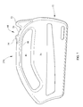
- FIG. 4 is a side view of the medical line manager of FIG. 2 ;
- FIG. 5 is a top view of the medical line manager of FIG. 2 ;
- FIG. 6 is a side view of the person-support apparatus of FIG. 1 showing the medical line manager integrated at the end of the siderail of FIG. 1 ;
- FIG. 7 is a side view of the siderails of FIG. 1 with the integrated medical line manager in a foot siderail;
- FIG. 8 is a side view of the siderails of FIG. 1 in a first position
- FIG. 9 is a side view of the siderails of FIG. 1 in a second position.
- FIG. 10 is a perspective side view of a person-support apparatus with a medical line manager integrated into an endboard.
- One illustrative embodiment of the present disclosure can include a siderail having a medical line manager integrated therein that can be configured to receive at least one medical line and maintain the medical line within the medical line manager.
- FIG. 1 A person-support apparatus 10 according to one illustrative embodiment of the current disclosure is shown in FIG. 1 .
- the person-support apparatus 10 can have a first section F 1 or head support section F 1 , where the head of a person can be positioned, and a second section S 1 or a foot support section S 1 , where the feet of the person can be positioned.
- the first section F 1 and the second section S 1 can be portions of the same section.
- the person-support apparatus 10 can be a hospital bed. It should be appreciated that the person-support apparatus 10 can also be a hospital stretcher or an operating table.
- the person-support apparatus 10 can include a lower frame 12 or base 12 , a plurality of supports 14 coupled with the lower frame 12 , and an upper frame 16 supported on the supports 14 above the lower frame 12 .
- the supports 14 can be lift mechanisms 14 that can move the upper frame 16 with respect to the lower frame 12 .
- the person-support apparatus 10 can support a person-support surface 18 thereon. It should be appreciated that the supports 14 can move the upper frame 16 to a Trendelenburg and/or a reverse Trendelenburg position with respect to the lower frame 12 .
- the upper frame 16 can define a longitudinal axis X 1 and a lateral axis Y 1 as shown in FIG. 1 .
- the longitudinal axis X 1 can extend at least the length of the person-support apparatus 10 through the first section F 1 and the second section S 1 along the lateral center of the upper frame 16 .
- the lateral axis Y 1 can be perpendicular the longitudinal axis X 1 and extend at least the width of the person-support apparatus 10 through the longitudinal center of the upper frame 16 .
- the upper frame 16 can include an intermediate frame 20 , a deck 22 , and siderails 24 as shown in FIGS. 1 and 2 .
- the upper frame 16 can include endboards, for example, a headboard HB 1 and a footboard FB 1 , coupled thereto.
- the intermediate frame 20 can be coupled with the supports 14 and can support the deck 22 thereon as shown in FIGS. 1 and 2 .
- the deck 22 can include a head portion 26 , a seat portion 28 , and a foot portion 30 .
- the head portion 26 , the seat portion 28 , and the foot portion 30 can be movably coupled with each other and the intermediate frame 20 .
- the siderails can define a siderail axis SX 1 that can be parallel the longitudinal axis X 1 as shown in FIGS. 1-9 .
- the siderails 24 can include a siderail body 32 with a top portion ST 1 , a bottom portion SB 1 , an end portion SE 1 , and a siderail linkage 34 as shown in FIGS. 1-9 .
- the siderails 24 can have a thickness TS 1 of less than 3 inches. it should be appreciated that the siderails 24 can have a thickness TS 1 of between about 1.5 inches and about 2 inches.
- the siderail linkage 34 can be coupled to the bottom portion SB 1 of the siderail body 32 and can couple the siderails 24 to the deck 22 and/or the intermediate frame 20 as shown in FIG. 1 .
- the siderails 24 can be coupled to the head portion 26 of the deck 22 (i.e., a first siderail 24 a or a head siderail 24 a ) and/or coupled to the foot portion 30 of the deck 22 and/or the intermediate frame 20 (i.e., a second siderail 24 b or a foot siderail 24 b ) as shown in FIG. 1 .
- the siderail linkage 34 can be configured to can facilitate movement of the siderails 24 between a deployed/operation position and a storage position.
- the siderail linkage 34 can include a locking mechanism (not shown) that can maintain the siderails 24 in one of the operating and/or storage position when locked and can help facilitate movement of the siderails 24 between the operating and storage position when unlocked.
- the siderail body 32 can include a first surface 36 , a second surface 38 , a third surface 40 or side surface 40 extending between the first surface 36 and the second surface 38 , a grip portion 42 , and a medical line manager 44 as shown in FIGS. 1-9 .
- the siderail 24 can include a caregiver interface (not shown) that can be operable to control various functionalities of the person-support apparatus 10 .
- At least a portion of the first surface 36 and the second surface 38 can be substantially parallel to one another.
- the first surface 36 can be oriented such that the first surface 36 faces toward the upper frame 16 and the second surface 38 can be oriented such that the second surface 38 faces away from the upper frame 16 .
- the grip portion 42 can be configured to be gripped by a person to assist the person with ingress/egress from the person support apparatus 10 as shown in FIGS. 1-9 .
- the grip portion 42 can be located along the top portion ST 1 and can include a grip opening 46 that can pass through the siderail body 32 and define an inner surface 48 of the grip portion 42 as shown in FIGS. 1-9 .
- the medical line manager 44 can be integrated into the side surface 40 of the siderail 24 as shown in FIGS. 1-9 . In one illustrative embodiment, the medical line manager 44 can be integrated into the side surface 40 along the top portion ST 1 of the head siderail 24 a as shown in FIGS. 1-5 and 7-9 . In another illustrative embodiment, the medical line manager 44 can be integrated into the side surface 40 along the end portion SE 1 of the siderail 24 as shown in FIG. 6 . In yet another embodiment, the medical line manager 44 can be integrated into the side surface 40 along the top portion ST 1 of the foot siderail 24 b as shown in FIGS. 1-5 and 7-9 . In still another embodiment, the medical line manager 44 can be integrated into a portion of the grip portion 42 as shown in FIGS.
- more than one medical line manager 44 can be integrated into at least one of the side surface 40 , the fist surface 36 , and the second surface 38 . It should also be appreciated that the medical line manager can be integrated into at least one of the first surface 36 and the second surface 38 . It should further be appreciated that the medical line manager 44 can be integrated into at least one surface of at least one of the headboard HB 1 and footboard FB 1 as shown in FIG. 10 .
- the medical line manager 44 can be configured to receive and removably retain at least one medical line 50 therein. In one illustrative embodiment, the medical line manager 44 can be configured to removably retain between about 1 medical line 50 and about 8 medical lines 50 . In another illustrative embodiment, the medical line manager 44 can be configured to removably retain at least about 4 IV's at about 28 FR (French) or about 0.367 inches. In yet another illustrative embodiment, the medical line 50 can have a diameter of less than about 1 inch in diameter. It should be appreciated that the medical line manager 44 can be configured to removably retain more or less medical lines 50 , and/or larger or smaller medical lines 50 .
- the medical line 50 can be or can include an intravenous line, an oxygen line, a catheter, cardiac lines, oxygen tubing, EKG/EEG/ECG electrodes, feed tubes, and other such medical tubing and medical wirings.
- the medical line 50 can be cable wires 50 , for example, power cables, monitor wires and other such wirings.
- the medical line manager 44 can help reduce strain on the medical lines 50 and tangling of the medical lines 50 .
- the medical line manager 44 can also be configured to allow for easy removal of the at least one medical line 50 in various situations, for example, when a patient is moved. It should be appreciated that the medical line manager 44 can assist in managing and organizing the at least one medical line 50 attached to the patient, and preventing the at least one medical line 50 from being disconnected from the patient and/or equipment.
- the medical line manager 44 can include a first end 52 or first side 52 , a second end 54 or second side 54 , and a base 56 or bottom 56 that can extend between the first end 52 and the second end 54 as shown in FIGS. 1-9 .
- the first end 52 and the second end 54 can be defined by raised and recessed portions of the side surface 40 .
- the first end 52 and the second end 54 can be protrusions that can extend from the siderail 24 .
- the medical line manager 44 can be a groove as shown in FIG. 3 .
- the first end 52 can form a portion of the end portion SE 1 of the siderail 24 .
- the first end 52 and the second end 54 can be defined by a combination of raised and recessed portions. It should be appreciated that there may be more than one protrusion or recessed portion.
- the first end 52 can be spaced apart from the second end 54 and can be oriented such that the first end 52 and the second end 54 are not horizontally co-planar as shown in FIGS. 1-9 . It should be appreciated that the first end 52 and the second end 54 can be horizontally co-planar.
- the first end 52 can be partially vertically below the second end 54 when the siderail axis SX 1 is substantially parallel to the longitudinal axis X 1
- the base 56 can be a length L 1 at an angle A 1 with respect to the siderail axis SX 1 .
- the base 56 can be about 2 inches long at an angle of about 33° with respect to the siderail axis SX 1 .
- the base 56 can be angled such that the base 56 is tangent the inner surface 48 of the grip portion 42 . It should be appreciated that the base 56 can be curved to mimic the inner surface 48 of the grip portion 42 . It should also be appreciated that the base 56 can have a length of more or less than 2 inches.
- the first end 52 can include a first engagement surface 58 and a transition portion 60 that can connect the first engagement surface 58 to the base 56 as shown in FIGS. 1-9 .
- the first engagement surface 58 can form a first angle FA 1 with respect to the base 56 and can have a first length FL 1 .
- the first engagement surface 58 can form an angle of about 90° with respect to the base 56 (about 123° with respect to the siderail axis SX 1 ) and can be about 0.7 inches long.
- the first engagement surface 58 can form an angle of between about 127° and about 90° with respect to the base 56 (between about 160° and about 120° with respect to the siderail axis SX 1 ). It should be appreciated that the first engagement surface 58 can form an angle of greater or less than about 90° with respect to the base 56 and can be more or less than about 0.7 inches in length.
- the transition portions 60 can help prevent the medical lines 50 from catching or snagging on the medical line manager 44 as shown in FIGS. 1-9 .
- the transition portions 60 can be curved as shown in FIGS. 1-9 . It should be appreciated that the transition portions 60 can be ramps (not shown).
- the first end 52 can extend a first distance FD 1 from the base 56 and can have a first thickness FT 1 as shown in FIGS. 1-9 .
- the first end 52 can extend at least about 1 . 4 inches from the base 56 and can have a thickness FT 1 equal to the thickness TS 1 of the siderail 24 .
- the first end 52 can be thickness FT 1 greater or less than the thickness TS 1 of the siderail 24 .
- the thickness FT 1 of the first end 52 can be less than about 3 inches. It should be appreciated that the first end 52 can extend more or less than 1.4 inches from the base 56 .
- At least a portion of the first end 52 can be curved as shown in FIGS. 1-9 .
- the first end 52 can have a radius of curvature of about half the first distance FD 1 .
- the radius of curvature can be about 0.7 inches. It should be appreciated that at least a portion of the first end 52 can be longitudinally curved and/or laterally curved.
- the second end 54 can include a second engagement surface 62 and a transition portion 64 that can connect the second engagement surface 62 to the base 56 as shown in FIGS. 1-9 .
- the second engagement surface 62 can form a second angle SA 1 with respect to the base 56 and have a second length SL 1 .
- the second engagement surface 62 can form an angle of about 120° with respect to the base 56 (about 90° with respect to the siderail axis SX 1 ) and can be less than about 0.6 inches long.
- the second engagement surface 62 can form an angle of between about 120° and about 100° with respect to the base 56 (between about 90° and about 70° with respect to the siderail axis SX 1 ).
- the second engagement surface 62 can form an angle of greater than about 120° or less than about 100° with respect to the base 56 (greater than about 90° or less than about 70° with respect to the siderail axis SX 1 ) and can have a length of greater than about 0.6 inches.
- the second end 54 can extend a second distance SD 1 from the base 56 and can have a second thickness ST 1 as shown in FIGS. 1-9 .
- the second end 54 can extend at least about 0.5 inches from the base 56 and can have a thickness ST 1 that is less than the thickness TS 1 of the siderail 24 .
- the second end 54 can be a thickness ST 1 that is greater or less than the thickness TS 1 of the siderail 24 .
- the thickness ST 1 of the second end 54 can be less than about 3 inches.
- the thickness ST 1 of the second end 54 can be between about 1.5 inches and 2 inches.
- the second end 54 can extend more or less than 0.5 inches from the base 56 .
- At least a portion of the second end 54 can be curved as shown in FIGS. 1-9 .
- the second end 54 can have a radius of curvature of about half the second distance SD 1 .
- the radius of curvature can be 0.25 inches. It should be appreciated that at least a portion of the second end 54 can be longitudinally curved and/or laterally curved as shown in FIGS. 3-4 .
- the medical line manager 44 can be in a first position where the first section F 1 and the second section S 1 are generally horizontal as shown in FIG. 6 .
- At least one medical line 50 can be positioned within the medical line manager 44 and can engage at least one of the first end 52 , second end 54 , base 56 , and the transition portions 58 .
- the medical line manager 44 can move from the first position to a second position as shown in FIG. 7 .
- the first section F 1 and the second section S 1 can move with respect to horizontal to a second position, for example, Trendelenburg and reverse Trendelenburg.
- the medical line 50 can move within the medical line manager 44 between the first end 52 and the second end 54 and engage various portions of the medical line manager 44 to maintain the medical line 50 within the medical line manager 44 .
- the medical line 50 can be moved from between the first end 52 and the second end 54 , for example, by being pulled or slid over the first end 52 or the second end 54 . It should be appreciated that the medical line 50 can be lifted out from between the first end 52 or the second end 54 to remove the medical line 50 from the medical line manager 44 .
- a person-support apparatus comprises a frame and a siderail.
- the frame is configured to support a person thereon.
- the siderail is coupled to the frame.
- the siderail includes a siderail body with a first surface, a second surface, and a third surface extending between about the first surface and the second surface.
- the first surface is oriented such that the first surface faces toward the frame and the second surface is oriented such that the second surface faces away from the frame.
- the third surface includes a medical line manager configured to receive and removably retain at least one medical line therein.
- a siderail assembly comprises a siderail and a medical line manager.
- the siderail includes a siderail body having a first surface, a second surface, and a side surface extending between about the first surface and about the second surface.
- the medical line manager is integrated into at least one of the first surface, the second surface, and the side surface of the siderail.
- the medical line manager includes a first side, a second side, and a bottom extending between about the first side and the second side.
- the medical line manager is configured to receive and removably retain at least one medical line therein.
- a person-support apparatus comprises a frame, an endboard, a siderail, and a medical line manager.
- the frame includes a first end and a second end with a longitudinal axis extending through the first end and the second end and a lateral axis substantially perpendicular to the longitudinal axis.
- the endboard is coupled to at least one of the first end and the second end of the frame.
- the siderail is coupled to a frame.
- the medical line manager is integrated into at least one of the endboard and the siderail.
- the medical line manager including a first side, a second side, and a bottom extending between about the first side and about the second side, the medical line manager is configured to receive and removably retain at least one medical line therein.
Landscapes
- Health & Medical Sciences (AREA)
- Life Sciences & Earth Sciences (AREA)
- Animal Behavior & Ethology (AREA)
- General Health & Medical Sciences (AREA)
- Public Health (AREA)
- Veterinary Medicine (AREA)
- Nursing (AREA)
- Heart & Thoracic Surgery (AREA)
- Engineering & Computer Science (AREA)
- Anesthesiology (AREA)
- Biomedical Technology (AREA)
- Hematology (AREA)
- Pulmonology (AREA)
- Emergency Medicine (AREA)
- Vascular Medicine (AREA)
- Invalid Beds And Related Equipment (AREA)
Abstract
Description
Claims (17)
Priority Applications (1)
| Application Number | Priority Date | Filing Date | Title |
|---|---|---|---|
| US15/296,767 US9931258B2 (en) | 2009-07-15 | 2016-10-18 | Medical line manager |
Applications Claiming Priority (3)
| Application Number | Priority Date | Filing Date | Title |
|---|---|---|---|
| US12/589,536 US20110010854A1 (en) | 2009-07-15 | 2009-07-15 | Siderail with storage area |
| US12/547,054 US9486374B2 (en) | 2009-07-15 | 2009-08-25 | Medical line manager |
| US15/296,767 US9931258B2 (en) | 2009-07-15 | 2016-10-18 | Medical line manager |
Related Parent Applications (1)
| Application Number | Title | Priority Date | Filing Date |
|---|---|---|---|
| US12/547,054 Continuation US9486374B2 (en) | 2009-07-15 | 2009-08-25 | Medical line manager |
Publications (2)
| Publication Number | Publication Date |
|---|---|
| US20170035634A1 US20170035634A1 (en) | 2017-02-09 |
| US9931258B2 true US9931258B2 (en) | 2018-04-03 |
Family
ID=43028810
Family Applications (2)
| Application Number | Title | Priority Date | Filing Date |
|---|---|---|---|
| US12/547,054 Active 2031-07-03 US9486374B2 (en) | 2009-07-15 | 2009-08-25 | Medical line manager |
| US15/296,767 Active US9931258B2 (en) | 2009-07-15 | 2016-10-18 | Medical line manager |
Family Applications Before (1)
| Application Number | Title | Priority Date | Filing Date |
|---|---|---|---|
| US12/547,054 Active 2031-07-03 US9486374B2 (en) | 2009-07-15 | 2009-08-25 | Medical line manager |
Country Status (3)
| Country | Link |
|---|---|
| US (2) | US9486374B2 (en) |
| EP (2) | EP2275071B1 (en) |
| JP (1) | JP2011019912A (en) |
Cited By (1)
| Publication number | Priority date | Publication date | Assignee | Title |
|---|---|---|---|---|
| US10835667B1 (en) | 2019-11-04 | 2020-11-17 | M. Maurice Rogers | IV comfort and safety assist device and method |
Families Citing this family (11)
| Publication number | Priority date | Publication date | Assignee | Title |
|---|---|---|---|---|
| US9486374B2 (en) * | 2009-07-15 | 2016-11-08 | Hill-Rom Services, Inc. | Medical line manager |
| US10489661B1 (en) | 2016-03-08 | 2019-11-26 | Ocuvera LLC | Medical environment monitoring system |
| US10600204B1 (en) | 2016-12-28 | 2020-03-24 | Ocuvera | Medical environment bedsore detection and prevention system |
| US20180256425A1 (en) * | 2017-03-07 | 2018-09-13 | Lynet Lingenfelter | Line Guiding Assembly |
| US10815897B2 (en) * | 2017-07-26 | 2020-10-27 | Unison Industries, Llc | Air turbine starter |
| US11116680B2 (en) | 2017-09-19 | 2021-09-14 | Stryker Corporation | Patient support apparatus for controlling patient ingress and egress |
| US11052005B2 (en) | 2017-09-19 | 2021-07-06 | Stryker Corporation | Patient support apparatus with handles for patient ambulation |
| US11160705B2 (en) | 2017-10-20 | 2021-11-02 | Stryker Corporation | Adjustable patient support apparatus for assisted egress and ingress |
| US11515128B2 (en) | 2018-08-28 | 2022-11-29 | Lam Research Corporation | Confinement ring with extended life |
| USD1006519S1 (en) * | 2021-02-11 | 2023-12-05 | Linet Spol. S R.O. | Side rail for bed |
| US20230162587A1 (en) * | 2021-11-19 | 2023-05-25 | Hill-Rom Services, Inc. | Authorization system for integrated feature of support apparatus |
Citations (28)
| Publication number | Priority date | Publication date | Assignee | Title |
|---|---|---|---|---|
| US1231452A (en) * | 1915-01-08 | 1917-06-26 | Ora M Sword | Clothes-hanger. |
| US1862237A (en) * | 1931-06-17 | 1932-06-07 | Bennett G Rohret | Bed table |
| US1865757A (en) * | 1929-07-02 | 1932-07-05 | Honsowetz Isabelle | Hanger |
| US2428649A (en) * | 1945-11-15 | 1947-10-07 | Franklin M Brown | Illuminated mirror |
| US2662715A (en) * | 1951-09-10 | 1953-12-15 | Mcknight William Ed | Support attachment for beds |
| US2913740A (en) * | 1957-03-11 | 1959-11-24 | Charles D Eldridge | Cord bracket for hospital beds |
| US3338538A (en) * | 1965-07-26 | 1967-08-29 | Matilda G Roche | Drainage tube holder for hospital beds |
| US4141524A (en) * | 1977-02-28 | 1979-02-27 | Corvese Jr Louis | Tube holder for immobile patients |
| US4262872A (en) * | 1979-02-28 | 1981-04-21 | American Hospital Supply Corporation | Collapsible pole assembly |
| US4690674A (en) * | 1986-05-12 | 1987-09-01 | Dalglish Herbert F | Intravenous tube assembly |
| US4988062A (en) * | 1988-03-10 | 1991-01-29 | London Robert A | Apparatus, system and method for organizing and maintaining a plurality of medical catheters and the like |
| US5094418A (en) * | 1990-09-07 | 1992-03-10 | Stryker Corporation | IV pole |
| US5160106A (en) * | 1992-01-16 | 1992-11-03 | Monick Michelle M | Adaptor for anesthesia equipment |
| US5334186A (en) * | 1992-11-09 | 1994-08-02 | Alexander Stephen M | Medical tubing and implement organizer |
| US5337430A (en) * | 1993-04-28 | 1994-08-16 | Schlein Allen P | Device for assisting a person to transfer into and from a bed |
| US5387177A (en) * | 1993-05-13 | 1995-02-07 | Span-America Medical Systems, Inc. | Adjustable pediatric incubator nest |
| US5678267A (en) * | 1995-07-11 | 1997-10-21 | Kinder; Florence E. | Medical examination table handle system |
| US6058531A (en) * | 1997-05-23 | 2000-05-09 | Carroll Intelli Corp. | Dual-position assist and guard rail for beds |
| US20030009952A1 (en) * | 2001-05-25 | 2003-01-16 | Gallant Dennis J. | Headwall |
| US20030056293A1 (en) * | 2001-08-15 | 2003-03-27 | Brooke Jason C. | Ambulatory assist arm apparatus |
| US20040186341A1 (en) * | 2001-10-05 | 2004-09-23 | Mcdermott Ian | Patient-support apparatus having line management system |
| USD503231S1 (en) * | 2003-10-31 | 2005-03-22 | Jason M. Daugherty | Bedside mattress-clamping intravenous line organizer and identifier |
| US20050120485A1 (en) * | 2002-03-05 | 2005-06-09 | Gemeline Sebastien | Handle for hospital bed |
| US20070181751A1 (en) * | 2006-02-08 | 2007-08-09 | Newkirk David C | Line management device |
| US20080163425A1 (en) * | 2007-01-08 | 2008-07-10 | White Robert D | Transferring and holding device for high-risk neonatal intensive care unit (NICU) patients |
| US7805789B1 (en) * | 2009-02-27 | 2010-10-05 | Mark Ronald Dean | Assist handle for a bed |
| US20110010852A1 (en) * | 2009-07-15 | 2011-01-20 | Heimbrock Richard H | Medical line manager |
| US20110185507A1 (en) * | 2010-02-02 | 2011-08-04 | Abernathey Ethan S | Assist handle assemblies and beds with an assist handle assembly |
Family Cites Families (3)
| Publication number | Priority date | Publication date | Assignee | Title |
|---|---|---|---|---|
| AU2003274957B2 (en) * | 2002-09-06 | 2009-07-16 | Hill-Rom Services, Inc. | Hospital bed |
| US7073220B2 (en) * | 2002-09-06 | 2006-07-11 | Hill-Rom Services, Inc. | Bed siderail having a latch |
| FI20031241A7 (en) * | 2003-09-02 | 2005-03-03 | Jouko Kettunen | Nursing bed |
-
2009
- 2009-08-25 US US12/547,054 patent/US9486374B2/en active Active
-
2010
- 2010-07-14 EP EP10251260.5A patent/EP2275071B1/en active Active
- 2010-07-14 EP EP13193268.3A patent/EP2716271A1/en not_active Withdrawn
- 2010-07-15 JP JP2010161011A patent/JP2011019912A/en active Pending
-
2016
- 2016-10-18 US US15/296,767 patent/US9931258B2/en active Active
Patent Citations (40)
| Publication number | Priority date | Publication date | Assignee | Title |
|---|---|---|---|---|
| US1231452A (en) * | 1915-01-08 | 1917-06-26 | Ora M Sword | Clothes-hanger. |
| US1865757A (en) * | 1929-07-02 | 1932-07-05 | Honsowetz Isabelle | Hanger |
| US1862237A (en) * | 1931-06-17 | 1932-06-07 | Bennett G Rohret | Bed table |
| US2428649A (en) * | 1945-11-15 | 1947-10-07 | Franklin M Brown | Illuminated mirror |
| US2662715A (en) * | 1951-09-10 | 1953-12-15 | Mcknight William Ed | Support attachment for beds |
| US2913740A (en) * | 1957-03-11 | 1959-11-24 | Charles D Eldridge | Cord bracket for hospital beds |
| US3338538A (en) * | 1965-07-26 | 1967-08-29 | Matilda G Roche | Drainage tube holder for hospital beds |
| US4141524A (en) * | 1977-02-28 | 1979-02-27 | Corvese Jr Louis | Tube holder for immobile patients |
| US4262872A (en) * | 1979-02-28 | 1981-04-21 | American Hospital Supply Corporation | Collapsible pole assembly |
| US4690674A (en) * | 1986-05-12 | 1987-09-01 | Dalglish Herbert F | Intravenous tube assembly |
| US4988062A (en) * | 1988-03-10 | 1991-01-29 | London Robert A | Apparatus, system and method for organizing and maintaining a plurality of medical catheters and the like |
| US5094418A (en) * | 1990-09-07 | 1992-03-10 | Stryker Corporation | IV pole |
| US5160106A (en) * | 1992-01-16 | 1992-11-03 | Monick Michelle M | Adaptor for anesthesia equipment |
| US5334186A (en) * | 1992-11-09 | 1994-08-02 | Alexander Stephen M | Medical tubing and implement organizer |
| US5337430A (en) * | 1993-04-28 | 1994-08-16 | Schlein Allen P | Device for assisting a person to transfer into and from a bed |
| US5387177A (en) * | 1993-05-13 | 1995-02-07 | Span-America Medical Systems, Inc. | Adjustable pediatric incubator nest |
| US5678267A (en) * | 1995-07-11 | 1997-10-21 | Kinder; Florence E. | Medical examination table handle system |
| US6058531A (en) * | 1997-05-23 | 2000-05-09 | Carroll Intelli Corp. | Dual-position assist and guard rail for beds |
| US20030009952A1 (en) * | 2001-05-25 | 2003-01-16 | Gallant Dennis J. | Headwall |
| US6728985B2 (en) * | 2001-08-15 | 2004-05-04 | Hill-Rom Services, Inc. | Ambulatory assist arm apparatus |
| US20030056293A1 (en) * | 2001-08-15 | 2003-03-27 | Brooke Jason C. | Ambulatory assist arm apparatus |
| US7357772B2 (en) * | 2001-10-05 | 2008-04-15 | Draeger Medical Systems, Inc. | Patient-support apparatus having line management system |
| US20040186341A1 (en) * | 2001-10-05 | 2004-09-23 | Mcdermott Ian | Patient-support apparatus having line management system |
| US20050120485A1 (en) * | 2002-03-05 | 2005-06-09 | Gemeline Sebastien | Handle for hospital bed |
| US7039971B2 (en) * | 2002-03-05 | 2006-05-09 | Hill-Rom Services, Inc. | Handle for hospital bed |
| USD503231S1 (en) * | 2003-10-31 | 2005-03-22 | Jason M. Daugherty | Bedside mattress-clamping intravenous line organizer and identifier |
| US20100263123A1 (en) * | 2006-02-08 | 2010-10-21 | Newkirk David C | Line management device for a hospital bed |
| US8370977B2 (en) * | 2006-02-08 | 2013-02-12 | Hill-Rom Services, Inc. | Line management device for a hospital bed |
| US7766289B2 (en) * | 2006-02-08 | 2010-08-03 | Hill-Rom Services, Inc. | Line management device |
| US20070181751A1 (en) * | 2006-02-08 | 2007-08-09 | Newkirk David C | Line management device |
| US7850595B2 (en) * | 2007-01-08 | 2010-12-14 | White Robert D | Transferring and holding device for high-risk neonatal intensive care unit (NICU) patients |
| US20110087064A1 (en) * | 2007-01-08 | 2011-04-14 | White Robert D | Transferring and holding device for high-risk neonatal intensive care unit (NICU) patients |
| US8360953B2 (en) * | 2007-01-08 | 2013-01-29 | White Robert D | Transferring and holding device for high-risk neonatal intensive care unit (NICU) patients |
| US20080163425A1 (en) * | 2007-01-08 | 2008-07-10 | White Robert D | Transferring and holding device for high-risk neonatal intensive care unit (NICU) patients |
| US7805789B1 (en) * | 2009-02-27 | 2010-10-05 | Mark Ronald Dean | Assist handle for a bed |
| US20110010852A1 (en) * | 2009-07-15 | 2011-01-20 | Heimbrock Richard H | Medical line manager |
| US9486374B2 (en) * | 2009-07-15 | 2016-11-08 | Hill-Rom Services, Inc. | Medical line manager |
| US20170035634A1 (en) * | 2009-07-15 | 2017-02-09 | Hill-Rom Services, Inc. | Medical line manager |
| US20110185507A1 (en) * | 2010-02-02 | 2011-08-04 | Abernathey Ethan S | Assist handle assemblies and beds with an assist handle assembly |
| US8578531B2 (en) * | 2010-02-02 | 2013-11-12 | Medline Industries, Inc. | Assist handle assemblies and beds with an assist handle assembly |
Cited By (1)
| Publication number | Priority date | Publication date | Assignee | Title |
|---|---|---|---|---|
| US10835667B1 (en) | 2019-11-04 | 2020-11-17 | M. Maurice Rogers | IV comfort and safety assist device and method |
Also Published As
| Publication number | Publication date |
|---|---|
| EP2275071A3 (en) | 2011-07-20 |
| EP2275071A2 (en) | 2011-01-19 |
| US20110010852A1 (en) | 2011-01-20 |
| US9486374B2 (en) | 2016-11-08 |
| US20170035634A1 (en) | 2017-02-09 |
| EP2275071B1 (en) | 2013-11-20 |
| JP2011019912A (en) | 2011-02-03 |
| EP2716271A1 (en) | 2014-04-09 |
Similar Documents
| Publication | Publication Date | Title |
|---|---|---|
| US9931258B2 (en) | Medical line manager | |
| US8266741B2 (en) | Bed movement cessation based on IV pump alarm | |
| US8104729B2 (en) | Transferable patient care equipment support | |
| US6834402B2 (en) | Combination bed mover and patient transfer apparatus | |
| CA2632100C (en) | Patient single surface system | |
| US11806291B2 (en) | Patient support apparatus having bearing arrangement for deck extension assembly | |
| US9756954B2 (en) | Siderail assembly for patient support appartatus | |
| US8621688B2 (en) | Siderail assembly for patient support apparatus | |
| US20120246830A1 (en) | Footboard egress design | |
| US8453283B2 (en) | Patient support apparatus with movable siderail assembly | |
| EP2366371B1 (en) | Siderail assembly | |
| US11911326B2 (en) | Hospital bed headboard | |
| US8689372B2 (en) | Siderail handle | |
| US20120023659A1 (en) | Endboard assembly | |
| US8484778B2 (en) | Side rail with two position storage feature | |
| US12440410B2 (en) | Support assembly attachable to a patient support and patient support having same | |
| EP2644177A1 (en) | Footboard Egress Design |
Legal Events
| Date | Code | Title | Description |
|---|---|---|---|
| STCF | Information on status: patent grant |
Free format text: PATENTED CASE |
|
| AS | Assignment |
Owner name: JPMORGAN CHASE BANK, N.A., ILLINOIS Free format text: SECURITY AGREEMENT;ASSIGNORS:HILL-ROM HOLDINGS, INC.;HILL-ROM, INC.;HILL-ROM SERVICES, INC.;AND OTHERS;REEL/FRAME:050260/0644 Effective date: 20190830 |
|
| MAFP | Maintenance fee payment |
Free format text: PAYMENT OF MAINTENANCE FEE, 4TH YEAR, LARGE ENTITY (ORIGINAL EVENT CODE: M1551); ENTITY STATUS OF PATENT OWNER: LARGE ENTITY Year of fee payment: 4 |
|
| AS | Assignment |
Owner name: HILL-ROM HOLDINGS, INC., ILLINOIS Free format text: RELEASE OF SECURITY INTEREST AT REEL/FRAME 050260/0644;ASSIGNOR:JPMORGAN CHASE BANK, N.A.;REEL/FRAME:058517/0001 Effective date: 20211213 Owner name: BARDY DIAGNOSTICS, INC., ILLINOIS Free format text: RELEASE OF SECURITY INTEREST AT REEL/FRAME 050260/0644;ASSIGNOR:JPMORGAN CHASE BANK, N.A.;REEL/FRAME:058517/0001 Effective date: 20211213 Owner name: VOALTE, INC., FLORIDA Free format text: RELEASE OF SECURITY INTEREST AT REEL/FRAME 050260/0644;ASSIGNOR:JPMORGAN CHASE BANK, N.A.;REEL/FRAME:058517/0001 Effective date: 20211213 Owner name: HILL-ROM, INC., ILLINOIS Free format text: RELEASE OF SECURITY INTEREST AT REEL/FRAME 050260/0644;ASSIGNOR:JPMORGAN CHASE BANK, N.A.;REEL/FRAME:058517/0001 Effective date: 20211213 Owner name: WELCH ALLYN, INC., NEW YORK Free format text: RELEASE OF SECURITY INTEREST AT REEL/FRAME 050260/0644;ASSIGNOR:JPMORGAN CHASE BANK, N.A.;REEL/FRAME:058517/0001 Effective date: 20211213 Owner name: ALLEN MEDICAL SYSTEMS, INC., ILLINOIS Free format text: RELEASE OF SECURITY INTEREST AT REEL/FRAME 050260/0644;ASSIGNOR:JPMORGAN CHASE BANK, N.A.;REEL/FRAME:058517/0001 Effective date: 20211213 Owner name: HILL-ROM SERVICES, INC., ILLINOIS Free format text: RELEASE OF SECURITY INTEREST AT REEL/FRAME 050260/0644;ASSIGNOR:JPMORGAN CHASE BANK, N.A.;REEL/FRAME:058517/0001 Effective date: 20211213 Owner name: BREATHE TECHNOLOGIES, INC., CALIFORNIA Free format text: RELEASE OF SECURITY INTEREST AT REEL/FRAME 050260/0644;ASSIGNOR:JPMORGAN CHASE BANK, N.A.;REEL/FRAME:058517/0001 Effective date: 20211213 |
|
| MAFP | Maintenance fee payment |
Free format text: PAYMENT OF MAINTENANCE FEE, 8TH YEAR, LARGE ENTITY (ORIGINAL EVENT CODE: M1552); ENTITY STATUS OF PATENT OWNER: LARGE ENTITY Year of fee payment: 8 |