US9931063B2 - Sensor for measuring motor function, a plastic band, and a device for measuring motor function - Google Patents
Sensor for measuring motor function, a plastic band, and a device for measuring motor function Download PDFInfo
- Publication number
- US9931063B2 US9931063B2 US13/005,695 US201113005695A US9931063B2 US 9931063 B2 US9931063 B2 US 9931063B2 US 201113005695 A US201113005695 A US 201113005695A US 9931063 B2 US9931063 B2 US 9931063B2
- Authority
- US
- United States
- Prior art keywords
- magnetic field
- sensor
- motor function
- hole
- measuring motor
- Prior art date
- Legal status (The legal status is an assumption and is not a legal conclusion. Google has not performed a legal analysis and makes no representation as to the accuracy of the status listed.)
- Active, expires
Links
Images


Classifications
-
- A—HUMAN NECESSITIES
- A61—MEDICAL OR VETERINARY SCIENCE; HYGIENE
- A61B—DIAGNOSIS; SURGERY; IDENTIFICATION
- A61B5/00—Measuring for diagnostic purposes; Identification of persons
- A61B5/103—Measuring devices for testing the shape, pattern, colour, size or movement of the body or parts thereof, for diagnostic purposes
- A61B5/11—Measuring movement of the entire body or parts thereof, e.g. head or hand tremor or mobility of a limb
- A61B5/1124—Determining motor skills
- A61B5/1125—Grasping motions of hands
-
- A—HUMAN NECESSITIES
- A61—MEDICAL OR VETERINARY SCIENCE; HYGIENE
- A61B—DIAGNOSIS; SURGERY; IDENTIFICATION
- A61B5/00—Measuring for diagnostic purposes; Identification of persons
- A61B5/41—Detecting, measuring or recording for evaluating the immune or lymphatic systems
- A61B5/411—Detecting or monitoring allergy or intolerance reactions to an allergenic agent or substance
-
- A—HUMAN NECESSITIES
- A61—MEDICAL OR VETERINARY SCIENCE; HYGIENE
- A61B—DIAGNOSIS; SURGERY; IDENTIFICATION
- A61B2560/00—Constructional details of operational features of apparatus; Accessories for medical measuring apparatus
- A61B2560/04—Constructional details of apparatus
- A61B2560/0437—Trolley or cart-type apparatus
-
- A—HUMAN NECESSITIES
- A61—MEDICAL OR VETERINARY SCIENCE; HYGIENE
- A61B—DIAGNOSIS; SURGERY; IDENTIFICATION
- A61B2562/00—Details of sensors; Constructional details of sensor housings or probes; Accessories for sensors
- A61B2562/02—Details of sensors specially adapted for in-vivo measurements
- A61B2562/0223—Magnetic field sensors
Definitions
- the present invention relates to a sensor for measuring motor function concerning living body (for example, human body), a plastic band for attaching the sensor to the living body, and a device for measuring motor function receiving a signal from the sensor.
- a patient suffering from Parkinson's disease or cerebral infraction is likely to happen a physical dysfunction.
- the motor function of the patient can be exactly understood or recognized.
- a doctor has judged based on an experience, for example, by seeing that a patient practices an opening or closing action between his or her thumb and other finger, in case that the doctor judges the patient to be a good motor function or not. Then, the doctor used to judge a health condition of patient based on the experience by seeing his or her action.
- the motor function cannot be exactly judged based on such a subjective judgment.
- this applicant provides an art for measuring motor function of a subject for experiment at high accuracy by that the subject for experiment practices the opening or closing action of their fingers with coils wearing in each of the thumb and forefinger of the subject for experiment such as the patients, such that it is turned on electricity in one coil to generate a magnetic field and velocity, acceleration, or the like caused by the opening or closing action of fingers are analyzed according to a magnitude of induced electric current generated in the other coil.
- Japanese patent unexamined laid-open publication No. 246,126 of 2008 will be referred to
- an object of the present invention is to be made in view of the above problem and to provide a sensor and its related art to be easily used for measuring motor function of a living body.
- the present invention is characterized by a sensor for measuring motor function including a magnetic field generator attached to one of two predetermined positions in a living body changing mutual distance caused by an action of the living body to have a coil board generating a magnetic field by electrification, and a magnetic field detector attached to the other of the two predetermined positions in the living body to detect the magnetic field generated by the magnetic field generator and have the coil board generating an electric current having a magnitude corresponding to a strength of the magnetic field as detected. Furthermore, this sensor is characterized in that each of the magnetic field generator and the magnetic field detector is provided with plastics covering a whole coil board. The other matters will be later described. According to the present invention, a sensor or the related art to be easily used for measuring motor function in a living body can be provided.
- FIG. 1 is a block diagram of a sensor, a device for measuring motor function, and an analyzer relating to this embodiment.
- FIG. 2A is a view showing an outer configuration of sensors, cables, and connectors relating to this embodiment
- FIG. 2B is a view showing a constitution of the sensor
- FIG. 2C is a view as the sensor seen from a direction A of FIG. 2B
- FIG. 2D is a view showing a reverse side of a coil board.
- FIG. 3A is a view seeing an outer appearance of a silicone rubber band of this embodiment
- FIG. 3B is a view showing an appearance just before the sensor is attached to a finger with the silicone rubber band
- FIG. 3C is a view showing an appearance as the sensor attached to the finger with the silicone rubber band.
- FIG. 4 is a view showing an appearance as the sensors attached respectively to a thumb and a forefinger.
- FIG. 5A is a view showing an outer appearance of the other example of the silicone rubber band
- FIGS. 5B to 5D are views respectively showing appearances as the silicone rubber bands attached to fingers in a time series.
- FIG. 6A to 6D are views showing appearances as the silicone rubber bands in the other example attached to fingers in a time series in sequence of FIG. 5D .
- FIG. 7A is a view showing an appearance of the device for measuring motor function relating to this embodiment
- FIG. 7B is a view showing an appearance as the sensor connected through the cable and the connector to the device for measuring motor function.
- FIG. 8A is a view showing the device for measuring motor function with its panel being open of the present invention
- FIG. 8B is a view showing an appearance as the device for measuring motor function disposed in a lateral direction.
- a mode for carrying out this invention (hereinafter, referred to as “embodiment”) will be described with reference to the above drawings.
- a subject for experiment means a living body (human, animal, etc.) as a subject for measuring motor function, it means human in this description.
- a system S for measuring motor function relating to this embodiment is indicated to make a finger-tapping movement to open or close human thumb and forefinger as soon as possible to a subject for experiment and measure the motor function of the subject for experiment in accordance with this movement of fingers.
- a system for measuring motor function S is constituted by a sensor 1 a (magnetic field detector), 1 b (magnetic field generator) (it is, hereinafter, referred to as “sensor 1 ” except that a distinction between the sensors 1 a , 1 b exists), a device for measuring motor function 2 , and an analyzer 3 .
- a sensor for measuring motor function is constituted by the magnetic field detector and the magnetic field generator, the magnetic field detector is called by the sensor 1 a , and the magnetic field generator is called by the sensor 1 b , for convenience of explanation, in this embodiment.
- the sensor 1 a , 1 b are worn in two fingers (for example, thumb and forefinger) of subject for experiment.
- the sensor 1 is connected to a cable 4 , and the cable 4 is connected to a connector 5 .
- a constitution of the sensor 1 will be later described.
- the device for measuring motor function 2 is a device positioned between the sensor 1 and the analyzer 3 .
- This device 2 is provided with an AC generator 201 , a current detector 202 , and A (analog)/D (Digital) converter 203 to be materialized by various kinds of electronic circuits.
- the AC generator 201 is designed to generate alternative current with predetermined cycle.
- the current detector 202 is designed to detect electric current from the sensor 1 received through the cable 4 and the connector 5 .
- the A/D converter 203 is designed to convert a value of electric current detected by the current detector 202 to a digital signal, and output the digital signal to the analyzer 3 .
- a constitution of the device for measuring motor function 2 will be later described.
- the AC generator 201 of the device for measuring motor function 2 generates alternative current having a specific frequency (for example, 20 kHz etc.).
- the alternative current is supplied through the connector 5 and the cable 4 to the sensor 1 b .
- the sensor 1 b receiving alternative current generates a magnetic field and the magnetic field changes constantly.
- the sensor 1 a generates an induced current by an electromagnetic induction caused by a change of magnetic field.
- a magnitude of the induced current becomes smaller, as a distance between the sensors 1 a , 1 b becomes larger.
- the current detector 202 is designed to detect an induced current generated by the sensor 1 a through the cable 4 and the connector 5 to supply the data to the A/D converter 203 .
- the A/D converter 203 converts a waveform data of the data (analogue signals of the induced current) received from the current detector 202 to a waveform data of the digital signal at the predetermined sampling frequency to send the converted digital signal to the analyzer 3 .
- the analyzer 3 is a computer device and analyzes motor function of a subject for experiment in accordance with the basis of digital signal received from the A/D converter 203 .
- the device for measuring motor function 2 may be appropriately provided with an amplifier circuit, a phase adjustment circuit, LPF (Low-Pass Filter), and the like, besides the above constitution.
- LPF Low-Pass Filter
- the sensor 1 and a constitution of the plastic band for attaching the sensor 1 to fingers of a subject for experiment will be described. As shown in FIG. 2A , the sensor 1 is connected to the cable 4 , and the cable 4 is connected to the connector 5 .
- the sensor 1 is constituted by covering a coil board 11 having a coil portion 12 by a plastics 101 including a pin 102 and a nail contact portion 103 .
- the sensor 1 can make high in strength by covering the whole coil board 11 by the plastics 101 , and corrosions and damages of the coil board 11 can be preferably prevented.
- the coil board 11 is functioned as a means of magnetic field generation or a means of magnetic field detection. For example, it is materialized by piling multi-layer coil portion 12 on glass epoxy board or the like.
- the coil board is supposed to refer to the above publication as described in detail, and an explanation thereof will not be further described.
- a pin 102 is constituted to provide a ball-like protrusion on a base like a form of thin disc to form a part of plastics 101 .
- the pin 102 is a means for securing a silicone rubber band 111 (plastic band, or band made of silicone), 121 (plastic band), as described later, to the sensor 1 . The detail thereof will be later described.
- the nail contact portion 103 is a portion being in contact with a finger nail when the sensor 1 is attached to the finger of subject for experiment in a part of the plastics 101 to have a curve directed along a form of the finger.
- the subject for experiment can have a comfortable feeling of wearing when the sensor 1 is attached to the finger by the nail contact portion 103 having this curve.
- the nail contact portion 103 is made of relatively soft plastics, the subject for experiment can have a comfortable feeling of wearing and reduce a possibility damaging nail or skin.
- FIG. 2D is a view showing a reverse side of the coil board 11 .
- a conducting wire 16 of the coil portion 12 is adhered by soldering at a solder joint portion 14 .
- the conducting wire 16 is connected to the cable 4 .
- the cable 4 is let off from a reverse side of the coil board 11 through a hole 13 to a front side of the coil board 11 .
- a connection between the conducting wire 16 and the cable 4 is adhered by an adhesion portion 15 to the coil board 11 .
- a tensile strength of the conducting wire 16 is remarkably increased by letting out the cable 4 from a reverse side of the coil board 11 through the hole 13 to the surface side and adhering the connection between the conducting wire 16 and the cable 4 to the coil board 11 at the adhesion portion 15 .
- the cable 4 is pulled, a whole force thereof does not travel directly, and the conducting wire or the like can be prevented from cutting itself.
- the load applied to the solder joint portion 14 can be remarkably decreased and a fitting of the conducting wire 16 can be confirmed for sure. As shown in FIG.
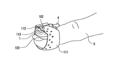
- a silicone rubber band 111 as one example of the plastic band is thin in thickness, and the whole body is formed like a substantially crescent swelling in the middle seeing from top (in case of a direction perpendicular to the thickness).
- the silicone rubber band 111 has two holes 112 and sixteen holes 113 .
- the pin 102 is designed to pass through one of holes 112 of the silicone rubber band 111 of the sensor 1 , and a swelling side of the silicone rubber band 111 is set to be placed in the base side.
- the silicone rubber band 111 is wound around the finger 6 to pass the pin 102 in one of the holes 113 in a slightly tensile condition.
- the silicone rubber band 111 can be uniformly in contact with the whole finger 6 and a stable feeling of wearing can be obtained.
- the sensor 1 a can be attached by the silicone rubber band 111 to a finger (forefinger) 6 a and the sensor 1 b can be attached by the silicone rubber band 111 to a finger (thumb) 6 b .
- the cable 4 is adhered by a cable clip 41 to clothes 42 , an accident, as the sensor pulled by the cable 4 , can be effectively avoided, then the stability for attaching the sensor 1 to the finger 6 can be remarkably improved.
- the subject for experiment makes the finger-tapping movement in a condition shown in FIG. 4 .
- a silicone rubber band 121 comprises a sensor cover 122 wound around the sensor 1 and a finger holder 123 having a substantially crescent form (a part thereof and the sensor cover 122 are mutually overlapped, a portion substantially forming a crescent) wound around the finger 6 .
- the sensor cover 122 and the finger holder 123 are integrally constituted to be substantially like a letter “L”.
- the sensor cover 122 is provided with a hole 124 , a slit 125 , and a hole 126 .
- the finger holder 123 is provided with sixteen holes 127 besides the hole 126 .
- the slit 125 of the silicone rubber band 121 is passed through the slit 125 of the silicone rubber band 121 .
- the pin 102 of the sensor 1 is passed through the hole 124 of the silicone rubber band 121 .
- the pin 102 of the sensor 1 is passed through the hole 126 of the silicone rubber band 121 .
- the silicone rubber band 121 is wound around the finger 6 to pass the pin 102 through one of the holes 127 in a slightly tensile condition.
- the silicone rubber band 121 is integrally constituted by the sensor cover 122 and the finger holder 123 , it makes no possibility for attaching to the finger 6 with the finger holder 123 turned upside down in a swelling direction of substantially crescent form thereof.
- the sensor 1 As the sensor 1 is covered by the sensor cover 122 , the sensor 1 is not in direct contact with the finger 6 . Accordingly, in case where the sensor 1 is made of materials possible to cause an allergic reaction, a possibility for causing an allergic reaction can be greatly decreased for a subject for experiment. It is mild or gentle to be in contact with the finger 6 , as it is made of silicone to be softer than the plastics 101 of the sensor 1 . Furthermore, the friction caused by being in contact with the finger 6 becomes large and it can be effectively prevented from occurring a slide between the sensor 1 and the finger 6 (nail).
- the silicone rubber band 121 and the sensor 1 can be easily separated.
- the slit 125 is provided in a position and a magnitude as shown in FIG. 5A .
- the silicone rubber band 121 When the silicone rubber band 121 is wound around the sensor 1 , the both can be mutually in close contact, and the stability for attaching the sensor 1 to the finger 6 can be improved.
- the device for measuring motor function 2 is constituted by a main body portion 21 , a grip 22 , a panel 23 (door), and a base 24 .
- the main body portion 21 is formed like a substantially parallelepiped shape to house an AC generator 201 (Referring to FIG. 1 ), a current detector 202 (Referring to FIG. 1 ), and an A/D converter 203 (Referring to FIG. 1 ) therein.
- the main body portion 21 is provided with an Input/Output terminal 211 used for connecting to the analyzer 3 with cables, and power source switch 25 for switching On-or-Off of the device for measuring motor function 2 .
- the grip 22 is attached to the main body portion 21 and is positioned to be upper in a vertical direction of center of gravity of the device for measuring motor function 2 when it is supported by the base 24 .
- the grip 22 is provided in such a position, the device for measuring motor function 2 does not tilt at the time of lifting the device for measuring motor function 2 with the grip 22 held. Then, it is convenient for transporting or the like.
- a space under the grip 22 as shown in Figures can be maintained to be large, a person carrying the device for measuring motor function 2 is easy to hold the grip 22 .
- the panel 23 is openably or closably attached by a hinge to the main body portion 21 .
- the width w formed between the panel 23 and the main body portion 21 is constituted not to pinch user's finger in this gap, that is, to be around 20 mm in this description.
- the base 24 is designed to be a member supporting the main body portion 21 and has a space for containing the main body portion 21 and the panel 23 seeing from top (in case of a direction seeing from the grip 22 ).
- the main body portion 21 is provided with a storage section 26 and a lamp 27 at a portion to be seen at the time of opening the panel 23 .
- the storage section 26 is used for winding the cable 4 connected to the sensor 1 in an outer circumference.
- the storage section 26 is provided with a storage section of replacement silicone rubber band 261 , storage section of calibration block 262 , hooks 263 , 264 , and a magnet for holding panel 265 .
- the storage section of replacement silicone rubber band 261 is a space for housing the silicone rubber band 111 , 121 . Then, the silicone rubber band 111 , 121 may be housed in a bag.
- the storage section of calibration block 262 is a space for housing the calibration block 7 .
- the calibration block 7 is an equipment used for calibration in relationship between the voltage data and the distance between fingers. As each of subjects for experiment has a difference in magnitude of fingers or the like, the subject for experiment grasps the calibration block 7 with his or her thumb and forefinger and calibrates by understanding a relationship between voltage data and distance between fingers.
- the calibration using the calibration block 7 will be referred to the above publication as described in detail, and a further explanation thereof will be omitted.
- the hooks 263 , 264 are members for preventing the cable 4 wound around an outer circumference of the storage section 26 from protruding outside.
- the magnet for holding the panel 265 is designed to magnetically attract a metal portion 231 provided in the panel 23 . Then, the panel 23 as closed is attached to the main body portion 21 in stability.
- the magnet for holding the panel 265 also plays a role to prevent the cable 4 wound around an outer circumference of the storage section 26 from protruding outside as well as the hooks 263 , 264 .
- the sensor 1 not in use and the cable 4 can be housed in compact by winding them around the storage section 26 , it is easy to carry the device for measuring motor function 2 , and the sensor 1 and the cable 4 can be protected from the outside situation.
- the storage section 26 is constituted by the sponge member, the possibility for damaging the cable wound around the storage section 26 or the sensor 1 can be decreased.
- the storage section of replacement silicone rubber band 261 housing the silicone rubber bands 111 , 121 and the storage section of calibration block 262 housing the calibration block 7 are provided inside the storage section 26 for winding the sensor 1 and the cable 4 , the space thereof can be effectively used.
- the base 24 is large enough to contain the main body portion 21 and the panel 23 as seen from top. Then, as shown in FIG. 8B , the device for measuring motor function 2 is constituted to unnaturally have an oblique angle, when the device for measuring motor function 2 is placed in a lateral direction.
- the device for measuring motor function 2 is constituted to unnaturally have an oblique angle, when the device for measuring motor function 2 is placed in a lateral direction.
- a finger for attaching the sensor 1 is not limited to a thumb or a forefinger, but may be the other finger such as a middle finger.
- the material of plastic band may not be made of silicone, but material other than silicone can be used if it is more excellent or substantially the same in quality of the property such as elasticity, softness, strength, durability, waterproof, biological safety, and temperature characteristics (the elasticity or the like is inconstant in case of varying in temperature). In a specific constitution, it may be appropriately changed without departing from a gist of the present invention.
Landscapes
- Health & Medical Sciences (AREA)
- Life Sciences & Earth Sciences (AREA)
- Medical Informatics (AREA)
- Molecular Biology (AREA)
- Veterinary Medicine (AREA)
- Biophysics (AREA)
- Pathology (AREA)
- Engineering & Computer Science (AREA)
- Biomedical Technology (AREA)
- Heart & Thoracic Surgery (AREA)
- Public Health (AREA)
- Physics & Mathematics (AREA)
- Surgery (AREA)
- Animal Behavior & Ethology (AREA)
- General Health & Medical Sciences (AREA)
- Immunology (AREA)
- Vascular Medicine (AREA)
- Physiology (AREA)
- Dentistry (AREA)
- Oral & Maxillofacial Surgery (AREA)
- Measurement Of The Respiration, Hearing Ability, Form, And Blood Characteristics Of Living Organisms (AREA)
Abstract
Description
Claims (15)
Applications Claiming Priority (2)
| Application Number | Priority Date | Filing Date | Title |
|---|---|---|---|
| JP2010-060716 | 2010-03-17 | ||
| JP2010060716A JP5416626B2 (en) | 2010-03-17 | 2010-03-17 | Motor function measurement sensor, motor function measurement system |
Publications (2)
| Publication Number | Publication Date |
|---|---|
| US20110230789A1 US20110230789A1 (en) | 2011-09-22 |
| US9931063B2 true US9931063B2 (en) | 2018-04-03 |
Family
ID=44647775
Family Applications (1)
| Application Number | Title | Priority Date | Filing Date |
|---|---|---|---|
| US13/005,695 Active 2033-09-03 US9931063B2 (en) | 2010-03-17 | 2011-01-13 | Sensor for measuring motor function, a plastic band, and a device for measuring motor function |
Country Status (2)
| Country | Link |
|---|---|
| US (1) | US9931063B2 (en) |
| JP (1) | JP5416626B2 (en) |
Cited By (4)
| Publication number | Priority date | Publication date | Assignee | Title |
|---|---|---|---|---|
| US20210153811A1 (en) * | 2019-11-27 | 2021-05-27 | International Business Machines Corporation | Modular sensing unit |
| USD1061904S1 (en) * | 2021-07-05 | 2025-02-11 | Maxell, Ltd. | Sensor attaching article |
| USD1061903S1 (en) * | 2021-07-05 | 2025-02-11 | Maxell, Ltd. | Sensor attaching article |
| USD1061902S1 (en) * | 2021-07-05 | 2025-02-11 | Maxell, Ltd. | Sensor attaching article |
Families Citing this family (2)
| Publication number | Priority date | Publication date | Assignee | Title |
|---|---|---|---|---|
| JP6709617B2 (en) * | 2015-12-25 | 2020-06-17 | マクセル株式会社 | Motor function measuring sensor and motor function measuring system |
| CN114053097B (en) * | 2021-11-26 | 2025-06-06 | 上海格润科技有限公司 | Gloves for hand rehabilitation training and coil inductors for hand rehabilitation training |
Citations (16)
| Publication number | Priority date | Publication date | Assignee | Title |
|---|---|---|---|---|
| US1610089A (en) * | 1923-09-28 | 1926-12-07 | Heitler Steven | Wound bandage and cover |
| US5170786A (en) * | 1990-09-28 | 1992-12-15 | Novametrix Medical Systems, Inc. | Reusable probe system |
| US5991648A (en) * | 1998-03-30 | 1999-11-23 | Palco Labs, Inc. | Adjustable pulse oximetry sensor for pediatric use |
| US20010053306A1 (en) * | 2000-06-14 | 2001-12-20 | Schneider Marc L. | Adjustable finger stylus |
| JP2002159473A (en) | 2000-11-22 | 2002-06-04 | Nikkiso Co Ltd | Weight check meter |
| JP2005095197A (en) | 2003-09-22 | 2005-04-14 | Hitachi Ltd | Biopsy device |
| US20060084855A1 (en) * | 2004-10-20 | 2006-04-20 | Drager Medical Ag & Co. Kgaa | Electrode belt for carrying out electrodiagnostic procedures on the human body |
| JP2006296618A (en) | 2005-04-19 | 2006-11-02 | Hitachi Ltd | Motion analysis display device and motion analysis method |
| JP2007029401A (en) | 2005-07-26 | 2007-02-08 | Hitachi Ltd | Motor function measuring device |
| JP2007054597A (en) | 2005-07-26 | 2007-03-08 | Hitachi Ltd | Motor function testing device |
| JP2007301003A (en) | 2006-05-09 | 2007-11-22 | Hitachi Ltd | Motor function testing device and phase comparison method between motion waveforms |
| US20080116360A1 (en) | 2006-11-17 | 2008-05-22 | Seiji Nakayama | Image input device |
| US20080238414A1 (en) | 2007-03-30 | 2008-10-02 | Tsuyoshi Miyashita | Motor function measuring sensor, motor function measuring apparatus, and motor function analyzing apparatus |
| JP2008238414A (en) | 2007-03-23 | 2008-10-09 | Seiko Epson Corp | Liquid jet head |
| US20080249406A1 (en) * | 2007-04-06 | 2008-10-09 | Aloka Co., Ltd. | Ultrasound diagnostic apparatus |
| US20100099962A1 (en) * | 2008-10-21 | 2010-04-22 | Quanta Computer Inc. | Sensing device and positioning structure thereof |
-
2010
- 2010-03-17 JP JP2010060716A patent/JP5416626B2/en active Active
-
2011
- 2011-01-13 US US13/005,695 patent/US9931063B2/en active Active
Patent Citations (23)
| Publication number | Priority date | Publication date | Assignee | Title |
|---|---|---|---|---|
| US1610089A (en) * | 1923-09-28 | 1926-12-07 | Heitler Steven | Wound bandage and cover |
| US5170786A (en) * | 1990-09-28 | 1992-12-15 | Novametrix Medical Systems, Inc. | Reusable probe system |
| US5991648A (en) * | 1998-03-30 | 1999-11-23 | Palco Labs, Inc. | Adjustable pulse oximetry sensor for pediatric use |
| US20010053306A1 (en) * | 2000-06-14 | 2001-12-20 | Schneider Marc L. | Adjustable finger stylus |
| JP2002159473A (en) | 2000-11-22 | 2002-06-04 | Nikkiso Co Ltd | Weight check meter |
| JP2005095197A (en) | 2003-09-22 | 2005-04-14 | Hitachi Ltd | Biopsy device |
| US20090069663A1 (en) | 2003-09-22 | 2009-03-12 | Hitachi, Ltd. | Living body inspection apparatus |
| US20060084855A1 (en) * | 2004-10-20 | 2006-04-20 | Drager Medical Ag & Co. Kgaa | Electrode belt for carrying out electrodiagnostic procedures on the human body |
| JP2006296618A (en) | 2005-04-19 | 2006-11-02 | Hitachi Ltd | Motion analysis display device and motion analysis method |
| US20060244744A1 (en) | 2005-04-19 | 2006-11-02 | Akihiko Kandori | Movement analysis display apparatus and movement analyzing method |
| US20070038067A1 (en) | 2005-07-26 | 2007-02-15 | Hitachi, Ltd. | Living body inspection apparatus |
| JP2007054597A (en) | 2005-07-26 | 2007-03-08 | Hitachi Ltd | Motor function testing device |
| US7419473B2 (en) | 2005-07-26 | 2008-09-02 | Hitachi, Ltd. | Living body inspection apparatus |
| JP2007029401A (en) | 2005-07-26 | 2007-02-08 | Hitachi Ltd | Motor function measuring device |
| JP2007301003A (en) | 2006-05-09 | 2007-11-22 | Hitachi Ltd | Motor function testing device and phase comparison method between motion waveforms |
| US20070272599A1 (en) | 2006-05-09 | 2007-11-29 | Tsuyoshi Miyashita | Moving body inspection apparatus and method of comparing phases between movement waveforms |
| US20080116360A1 (en) | 2006-11-17 | 2008-05-22 | Seiji Nakayama | Image input device |
| JP2008129719A (en) | 2006-11-17 | 2008-06-05 | Mitsumi Electric Co Ltd | Image input device |
| JP2008238414A (en) | 2007-03-23 | 2008-10-09 | Seiko Epson Corp | Liquid jet head |
| US20080238414A1 (en) | 2007-03-30 | 2008-10-02 | Tsuyoshi Miyashita | Motor function measuring sensor, motor function measuring apparatus, and motor function analyzing apparatus |
| JP2008246126A (en) | 2007-03-30 | 2008-10-16 | Hitachi Computer Peripherals Co Ltd | Motor function measuring sensor, motor function measuring device and motor function analyzing device |
| US20080249406A1 (en) * | 2007-04-06 | 2008-10-09 | Aloka Co., Ltd. | Ultrasound diagnostic apparatus |
| US20100099962A1 (en) * | 2008-10-21 | 2010-04-22 | Quanta Computer Inc. | Sensing device and positioning structure thereof |
Non-Patent Citations (1)
| Title |
|---|
| Japanese Office Action dated Aug. 6, 2013 in corresponding Japanese Patent Application No. 2010-060716. |
Cited By (5)
| Publication number | Priority date | Publication date | Assignee | Title |
|---|---|---|---|---|
| US20210153811A1 (en) * | 2019-11-27 | 2021-05-27 | International Business Machines Corporation | Modular sensing unit |
| US11850068B2 (en) * | 2019-11-27 | 2023-12-26 | International Business Machines Corporation | Modular sensing unit |
| USD1061904S1 (en) * | 2021-07-05 | 2025-02-11 | Maxell, Ltd. | Sensor attaching article |
| USD1061903S1 (en) * | 2021-07-05 | 2025-02-11 | Maxell, Ltd. | Sensor attaching article |
| USD1061902S1 (en) * | 2021-07-05 | 2025-02-11 | Maxell, Ltd. | Sensor attaching article |
Also Published As
| Publication number | Publication date |
|---|---|
| JP2011193905A (en) | 2011-10-06 |
| US20110230789A1 (en) | 2011-09-22 |
| JP5416626B2 (en) | 2014-02-12 |
Similar Documents
| Publication | Publication Date | Title |
|---|---|---|
| US9931063B2 (en) | Sensor for measuring motor function, a plastic band, and a device for measuring motor function | |
| US12232905B2 (en) | Acoustic sensor assembly | |
| US20240268783A1 (en) | Acoustic patient sensor coupler | |
| CN100536763C (en) | heart rate monitor | |
| US6553247B1 (en) | Electrode belt of heart rate monitor | |
| JP5843005B2 (en) | ECG signal measuring apparatus and ECG signal measuring method | |
| CN107949323B (en) | Biological information measuring device | |
| US20040019288A1 (en) | Patient-worn medical monitoring device | |
| WO2009020257A1 (en) | Pulse oximeter apparatus | |
| CN111093418B (en) | Wearable device | |
| CN108392200B (en) | Electrode assembly of an ECG monitoring device and its ECG monitoring device | |
| CN106132298A (en) | Biological information measurement device and pulse blood oxygen instrument | |
| US20100137701A1 (en) | Band with at least one sensor to be affixed toconvex unit | |
| JP2002143110A (en) | Heartbeat signal detection chest unit | |
| JP2021523813A (en) | Body sensor | |
| JP2017113367A (en) | Motion function measurement sensor and motion function measurement system | |
| JP2001190503A (en) | Organismic information measuring device | |
| JPH04129527A (en) | Pulse wave measuring device | |
| JP2022133931A (en) | Biopotential measurement electrode and biological information measurement device | |
| JP2007209610A (en) | Portable electrocardiograph | |
| KR101154167B1 (en) | Measuring apparatus for a body information | |
| CN112911991A (en) | Mobile monitoring equipment, mobile monitoring system and monitored body area system |
Legal Events
| Date | Code | Title | Description |
|---|---|---|---|
| AS | Assignment |
Owner name: HITACHI COMPUTER PERIPHERALS CO., LTD., JAPAN Free format text: ASSIGNMENT OF ASSIGNORS INTEREST;ASSIGNORS:AITA, TOSHIHIRO;DOI, AKITOSHI;NINOMIYA, ATSUSHI;AND OTHERS;SIGNING DATES FROM 20101203 TO 20101213;REEL/FRAME:025740/0010 |
|
| AS | Assignment |
Owner name: HITACHI CONSUMER ELECTRONICS CO., LTD., JAPAN Free format text: ASSIGNMENT OF ASSIGNORS INTEREST;ASSIGNOR:HITACHI COMPUTER PERIPHERALS CO., LTD.;REEL/FRAME:028266/0333 Effective date: 20120518 |
|
| AS | Assignment |
Owner name: HITACHI MAXELL, LTD., JAPAN Free format text: ASSIGNMENT OF ASSIGNORS INTEREST;ASSIGNOR:HITACHI CONSUMER ELECTRONICS CO., LTD.;REEL/FRAME:033558/0843 Effective date: 20140819 |
|
| AS | Assignment |
Owner name: MAXELL, LTD., JAPAN Free format text: ASSIGNMENT OF ASSIGNORS INTEREST;ASSIGNOR:HITACHI MAXELL, LTD.;REEL/FRAME:045142/0208 Effective date: 20171001 |
|
| STCF | Information on status: patent grant |
Free format text: PATENTED CASE |
|
| MAFP | Maintenance fee payment |
Free format text: PAYMENT OF MAINTENANCE FEE, 4TH YEAR, LARGE ENTITY (ORIGINAL EVENT CODE: M1551); ENTITY STATUS OF PATENT OWNER: LARGE ENTITY Year of fee payment: 4 |
|
| AS | Assignment |
Owner name: MAXELL HOLDINGS, LTD., JAPAN Free format text: MERGER;ASSIGNOR:MAXELL, LTD.;REEL/FRAME:058255/0579 Effective date: 20211001 |
|
| AS | Assignment |
Owner name: MAXELL, LTD., JAPAN Free format text: CHANGE OF NAME;ASSIGNOR:MAXELL HOLDINGS, LTD.;REEL/FRAME:058666/0407 Effective date: 20211001 |
|
| MAFP | Maintenance fee payment |
Free format text: PAYMENT OF MAINTENANCE FEE, 8TH YEAR, LARGE ENTITY (ORIGINAL EVENT CODE: M1552); ENTITY STATUS OF PATENT OWNER: LARGE ENTITY Year of fee payment: 8 |