US9928478B2 - Method and system for tracking equipment - Google Patents
Method and system for tracking equipment Download PDFInfo
- Publication number
- US9928478B2 US9928478B2 US14/182,750 US201414182750A US9928478B2 US 9928478 B2 US9928478 B2 US 9928478B2 US 201414182750 A US201414182750 A US 201414182750A US 9928478 B2 US9928478 B2 US 9928478B2
- Authority
- US
- United States
- Prior art keywords
- item
- equipment
- location
- placement
- agreement
- Prior art date
- Legal status (The legal status is an assumption and is not a legal conclusion. Google has not performed a legal analysis and makes no representation as to the accuracy of the status listed.)
- Expired - Fee Related, expires
Links
Images


Classifications
-
- G—PHYSICS
- G06—COMPUTING; CALCULATING OR COUNTING
- G06Q—INFORMATION AND COMMUNICATION TECHNOLOGY [ICT] SPECIALLY ADAPTED FOR ADMINISTRATIVE, COMMERCIAL, FINANCIAL, MANAGERIAL OR SUPERVISORY PURPOSES; SYSTEMS OR METHODS SPECIALLY ADAPTED FOR ADMINISTRATIVE, COMMERCIAL, FINANCIAL, MANAGERIAL OR SUPERVISORY PURPOSES, NOT OTHERWISE PROVIDED FOR
- G06Q10/00—Administration; Management
- G06Q10/08—Logistics, e.g. warehousing, loading or distribution; Inventory or stock management
- G06Q10/087—Inventory or stock management, e.g. order filling, procurement or balancing against orders
-
- G06F19/328—
-
- G—PHYSICS
- G16—INFORMATION AND COMMUNICATION TECHNOLOGY [ICT] SPECIALLY ADAPTED FOR SPECIFIC APPLICATION FIELDS
- G16H—HEALTHCARE INFORMATICS, i.e. INFORMATION AND COMMUNICATION TECHNOLOGY [ICT] SPECIALLY ADAPTED FOR THE HANDLING OR PROCESSING OF MEDICAL OR HEALTHCARE DATA
- G16H40/00—ICT specially adapted for the management or administration of healthcare resources or facilities; ICT specially adapted for the management or operation of medical equipment or devices
- G16H40/20—ICT specially adapted for the management or administration of healthcare resources or facilities; ICT specially adapted for the management or operation of medical equipment or devices for the management or administration of healthcare resources or facilities, e.g. managing hospital staff or surgery rooms
Definitions
- Various inventory systems maintain the status of manufactured products within inventory. This provides sellers of the products with various information in order to determine courses of action. For example, when a product has a low quantity within inventory, the product may be ordered or manufactured in preparation for potential future sales. However, information from these types of systems is typically limited to presence of products within the inventory and corresponding quantity information.
- Present invention embodiments include a tool to track manufactured and other products from cradle to grave. This includes tracking the history of locations where equipment has been placed, loaned, evaluated, stored, and sold.
- the system includes Return Authorization (RA) and Complaints for equipment and parts.
- RA Return Authorization
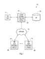
- FIG. 1 is a diagrammatic illustration of an example computing environment for use with an embodiment of the present invention.
- FIG. 2 is a schematic illustration of an example graphical user interface screen of a Users/Sales Executives home page.
- FIG. 3 is a schematic illustration of an example graphical user interface screen to enable a search.
- FIG. 4 is a schematic illustration of an example graphical user interface screen of a search window.
- FIG. 5 is a schematic illustration of an example graphical user interface screen of a textbox search fields example.
- FIG. 6 is a schematic illustration of an example graphical user interface screen of a drop-down menu search fields example.
- FIG. 7 is a schematic illustration of an example graphical user interface screen of a results grid for a search for equipment in Virginia.
- FIG. 8 is a schematic illustration of an example graphical user interface screen showing use of a results grid.
- FIG. 9 is a schematic illustration of an example graphical user interface screen of a equipment device details window.
- FIG. 10 is a schematic illustration of an example graphical user interface screen of a results grid with linked equipment.
- FIG. 11 is a schematic illustration of an example graphical user interface screen of linked equipment details.
- FIG. 12 is a schematic illustration of an example graphical user interface screen of an export dialogue box.
- FIG. 13 is a schematic illustration of an example graphical user interface screen for saving export results.
- FIG. 14 is a schematic illustration of an example graphical user interface screen for accessing resources.
- FIG. 15 is a schematic illustration of an example graphical user interface screen of a locations search page.
- FIG. 16 is a schematic illustration of an example graphical user interface screen of a results grid for a location search.
- FIG. 17 is a schematic illustration of an example graphical user interface screen of a location details page.
- FIG. 18 is a schematic illustration of an example graphical user interface screen of a location history page.
- FIG. 19 is a schematic illustration of an example graphical user interface screen of a placement types resources page.
- FIG. 20 is a schematic illustration of an example graphical user interface screen of a models resources page.
- FIG. 21 is a schematic illustration of an example graphical user interface screen of a catalogue resources page.
- FIG. 22 is a schematic illustration of an example graphical user interface screen of a territories resources page.
- FIG. 23 is a schematic illustration of an example graphical user interface screen of a regions resources page.
- FIG. 24 is a schematic illustration of an example graphical user interface screen of reports.
- FIG. 25 is a schematic illustration of an example graphical user interface screen of a report engine search parameters example.
- FIG. 26 is a schematic illustration of an example graphical user interface screen of a sample report.
- FIG. 27 is a schematic illustration of an example graphical user interface screen for new equipment entry.
- FIG. 28 is a schematic illustration of an example graphical user interface screen for creating linked equipment.
- FIG. 29 is a schematic illustration of an example graphical user interface screen for linked equipment.
- FIG. 30 is a schematic illustration of an example graphical user interface screen enabling selection of details to review linked equipment information.
- FIG. 31 is a schematic illustration of an example graphical user interface screen providing a link for linked equipment.
- FIG. 32 is a schematic illustration of an example graphical user interface screen for unlinking equipment.
- FIG. 33 is a schematic illustration of another example graphical user interface screen for unlinking equipment.
- FIG. 34 is a schematic illustration of an example graphical user interface screen for selection of equipment devices for placement.
- FIG. 35 is a schematic illustration of an example graphical user interface screen for entering new placement information.
- FIG. 36 is a schematic illustration of an example graphical user interface screen for alternative placement functionality.
- FIG. 37 is a schematic illustration of an example graphical user interface screen for deleting equipment.
- FIG. 38 is a schematic illustration of an example graphical user interface screen for managing locations.
- FIG. 39 is a schematic illustration of an example graphical user interface screen for editing locations.
- FIG. 40 is a schematic illustration of an example graphical user interface screen for creating new locations.
- FIG. 41 is a schematic illustration of an example graphical user interface screen providing a status indicator for equipment agreements in a location.
- FIG. 42 is a schematic illustration of an example graphical user interface screen for creating equipment agreements.
- FIG. 43 is a schematic illustration of an example graphical user interface screen of an equipment agreement details form.
- FIG. 44 is a schematic illustration of an example graphical user interface screen for adding equipment information to equipment agreement details.
- FIG. 45 is a schematic illustration of an example graphical user interface screen of a location details page with equipment agreement information.
- FIG. 46 is a schematic illustration of an example graphical user interface screen for editing placement types.
- FIG. 47 is a schematic illustration of an example graphical user interface screen for creating a new placement type.
- FIG. 48 is a schematic illustration of an example graphical user interface screen for editing models.
- FIG. 49 is a schematic illustration of an example graphical user interface screen for creating models.
- FIG. 50 is a schematic illustration of an example graphical user interface screen providing examples of modified equipment devices.
- FIG. 51 is a schematic illustration of an example graphical user interface screen for editing catalogues.
- FIG. 52 is a schematic illustration of an example graphical user interface screen for creating catalogues.
- FIG. 53 is a schematic illustration of an example graphical user interface screen for editing territories.
- FIG. 54 is a schematic illustration of an example graphical user interface screen for creating territories.
- FIG. 55 is a schematic illustration of an example graphical user interface screen for editing regions.
- FIG. 56 is a schematic illustration of an example graphical user interface screen for creating regions.
- FIG. 57 is a schematic illustration of an example graphical user interface screen for editing location classes.
- FIG. 58 is a schematic illustration of an example graphical user interface screen for creating a new location class.
- FIG. 59 is a schematic illustration of an example graphical user interface screen for creating a return authorization (RA).
- RA return authorization
- FIG. 60 is a schematic illustration of an example graphical user interface screen of an upper portion of an RA page.
- FIG. 61 is a schematic illustration of an example graphical user interface screen for entering return and replacement equipment.
- FIG. 62 is a schematic illustration of an example graphical user interface screen for providing reasons for a return.
- FIG. 63 is a schematic illustration of an example graphical user interface screen providing return and replacement equipment information.
- FIG. 64 is a schematic illustration of an example e-mail to customer service concerning replacement equipment.
- FIG. 65A is a schematic illustration of an example graphical user interface screen for adding equipment to an RA.
- FIG. 65B is a schematic illustration of an example graphical user interface screen of a replacement equipment table.
- FIG. 66 is a schematic illustration of an example graphical user interface screen for relating a new placement to an RA.
- FIG. 67 is a schematic illustration of an example graphical user interface screen showing automated RA status updates.
- FIG. 68 is a schematic illustration of an example graphical user interface screen for manually updating RA status.
- FIG. 69 is a schematic illustration of an example graphical user interface screen for the Quality Menu Items.
- FIG. 70 is a schematic illustration of an example graphical user interface screen for creating a drape RA.
- FIG. 71 is a schematic illustration of an example graphical user interface screen of a returned drapes grid.
- FIG. 72A is a schematic illustration of an example graphical user interface screen for creating a part type RA.
- FIG. 72B is a schematic illustration of an example graphical user interface screen of a return and replacement parts grid.
- FIG. 73 is a schematic illustration of an example graphical user interface screen of a RA search page.
- FIG. 74 is a schematic illustration of an example graphical user interface screen of a RA search results grid.
- FIG. 75 is a schematic illustration of an example graphical user interface screen providing details of an RA.
- FIG. 76 is a schematic illustration of an example graphical user interface screen for accessories returns.
- FIG. 77 is a schematic illustration of an example graphical user interface screen for searching complaints.
- FIG. 78 is a schematic illustration of an example graphical user interface screen for highlighting RA's complaint hyperlink.
- FIG. 79 is a schematic illustration of an example graphical user interface screen of an upper portion of a complaints page.
- FIG. 80 is a schematic illustration of an example graphical user interface screen of the lower portion of the complaints page.
- FIG. 81 is a schematic illustration of an example graphical user interface screen for creating a complaint for equipment.
- FIG. 82 is a schematic illustration of an example graphical user interface screen of an upper portion of a complaint.
- FIG. 83 is a schematic illustration of an example graphical user interface screen of the lower portion of the complaint.
- FIG. 84 is a schematic illustration of an example graphical user interface screen for cross-referencing complaint links in RAs.
- FIG. 85 is a schematic illustration of an example graphical user interface screen for copying complaints.
- FIG. 86 is a schematic illustration of an example graphical user interface screen for selecting a complaint type for copying.
- FIG. 87 is a schematic illustration of an example graphical user interface screen of complaint attachments.
- FIG. 88 is a schematic illustration of an example graphical user interface screen for adding complaint attachments.
- FIG. 89 is a schematic illustration of an example graphical user interface screen for browsing to a complaint attachment file.
- FIG. 90 is a schematic illustration of an example graphical user interface screen for uploading complaint attachments.
- FIG. 91 is a schematic illustration of an example graphical user interface screen of a complaints search page.
- FIG. 92 is a schematic illustration of an example graphical user interface screen of a Complaint search results grid.
- FIG. 93 is a schematic illustration of an example graphical user interface screen of a print Quality forms menu.
- FIG. 94 is a schematic illustration of an example graphical user interface screen for searching and printing RA Full Forms.
- FIG. 95 is a schematic illustration of an example graphical user interface screen of a RA Full Form print form.
- FIG. 96 is a schematic illustration of an example e-mail to shipping concerning an update to an RA.
- FIG. 97 is a schematic illustration of an example e-mail concerning deletion of RA equipment.
- FIG. 98 is a schematic illustration of an example graphical user interface screen for selecting complaints or RAs for printing.
- FIG. 99 is a schematic illustration of an example graphical user interface screen for managing QA resources.
- FIG. 100 is a schematic illustration of an example graphical user interface screen for entering a new reason for a return.
- environment 100 includes one or more server systems 110 , and one or more client or end-user systems 114 .
- the server systems preferably include one or more servers to handle various functions (e.g., security authentication, accounting, sales, electronic mail (e-mail), file operations, print operations, back-up operations, tracking, etc.).
- the environment may include various other devices for network communications and other functions (e.g., one or more printers, firewalls, access switches or hubs, routers, etc.).
- Server systems 110 and client systems 114 may be remote from each other and communicate over a network 112 .
- the network may be implemented by any number of any suitable communications media (e.g., wide area network (WAN), local area network (LAN), Internet, Intranet, etc.).
- server systems 110 and client systems 114 may be local to each other, and communicate via any appropriate local communication medium (e.g., local area network (LAN), hardwire, wireless link, Intranet, etc.).
- Client systems 114 enable users to interact with server systems 110 to perform equipment tracking and various other related functions (e.g., returns, complaints, etc.).
- the information (e.g., equipment attributes, locations, customers, etc.) is stored within one or more database systems 116 .
- the database systems may be implemented by any conventional or other databases or storage units, may be local to or remote from server systems 110 and client systems 114 , and may communicate via any appropriate communication medium (e.g., local area network (LAN), wide area network (WAN), Internet, hardwire, wireless link, Intranet, etc.).
- Server systems 110 include tracking and other modules to track equipment as described below.
- Client systems 114 may present a graphical user (e.g., GUI, etc.) or other interface (e.g., command line prompts, menu or other screens, etc.) to solicit information from users pertaining to the desired information and operations, and provide various reports.
- GUI graphical user
- other interface e.g., command line prompts, menu or other screens, etc.
- Server systems 110 and client systems 114 may be implemented by any conventional or other computer systems preferably equipped with a display or monitor, a base (e.g., including the processor, memories and/or internal or external communications devices (e.g., modem, network cards, etc.)), optional input devices (e.g., a keyboard, mouse or other input device), and any commercially available and/or custom software (e.g., server/communications software, tracking and other modules, browser/interface software, etc.).
- a base e.g., including the processor, memories and/or internal or external communications devices (e.g., modem, network cards, etc.)
- optional input devices e.g., a keyboard, mouse or other input device
- any commercially available and/or custom software e.g., server/communications software, tracking and other modules, browser/interface software, etc.
- one or more client systems 114 may perform equipment tracking and other operations when operating as a stand-alone unit.
- the client system stores or has access to the information, and includes the tracking and other modules to perform the operations.
- the graphical user e.g., GUI, etc.
- other interface e.g., command line prompts, menu or other screens, etc.
- Server system 110 includes various modules to process information and perform the tracking and other operations described below. Specifically, server system 110 includes tracking module 200 to track equipment and perform other operations as described below. The tracking and other modules of the server and client systems may be implemented by any combination of any quantity of software and/or hardware modules or units.
- Server systems 110 and/or client systems 114 perform various functions pertaining to tracking of equipment or other items as described below.
- present invention embodiments may be utilized to track equipment pertaining to medical thermal treatment devices (e.g., warming devices, cooling devices, accessories for these devices (e.g., drapes, etc.), etc.).
- present invention embodiments may be utilized to perform tracking and other functions for any desired items.
- the following table describes the roles and responsibilities for various users associated with the tracking functions (e.g., tracking module 200 ). In general, subordinate permissions sets are available to higher hierarchy roles. The exceptions to this policy are Accounting, QA roles, and the Restricted role, which are either independent (as with the Restricted role), or assigned in conjunction with other roles (as with the Accounting role). The roles are defined in the Table I below.
- SA Session ID
- EqT Admin Manage Territories and Regions Create and update placement information Maintain status levels for all Inventory Reconciliation Reviews BOL's and Pickup Forms Manage Equipment Agreements (EAs) Writer Create Equipment Place Equipment Manage EAs User QA, Customer Service, Conduct searches Sales Mgmt and Support, Run Reports MFG Maintenance, Exec Mgmt Regional Sales Search information (limited to their Managers region, including Sales Executives Inventory Locations and EAs) Submit Bill of Ladings (BOLs) and Pickup Forms (future) Run Selected Reports Sales Executives Sales Search information (limited to their territory, excluding Rep Inventory and EAs) Submit Bill of Ladings (BOLs)
- QA Writer QA Generate Complaints and RAs related to Complaints. Run Reports Ancillary role with access to functionality not available to any other role.
- QA Director QA Manage Complaints including completing selected fields in Complaints not accessible to any other role. All QA Writer functions QA User Customer Service, MFG, Search and run Reports EqT Admin, and Exec Management (including the Legal Department) RA Writer Shipping, Customer Customer Service creates Drape and Parts Service Manager RA Shipping creates Equipment RAs Run reports and search Manage RAs Restricted Customer Service Run selected reports only. I. Users With “User”, “Sales Executive” or Similar Roles
- the system is accessible using any commercial web browser. All users must be granted access and assigned a security role by the System Administrator. Once access is granted, the system will automatically check your network credentials and allow you to access the site. Users cannot access the system, unless they have logged into the network. The following is an example session to gain access.
- Sales Executives can only see equipment located in their territory. Access is not provided to Rep Inventory Locations in order to ensure accurate physical inventories. Regional Sales Managers can see equipment in their Region, including Rep Inventory Locations. The following is an example session to search for equipment.
- Search button On the menu bar displays the Search Window (See FIG. 4 —Search Window). Any combination of fields can be searched to refine the Results.
- the textbox fields display an “auto complete” list of valid values as you type. You select one of the items in the auto complete list. Refer to FIG. 5 .
- the following is an example session to search for equipment.
- the auto complete list will display all current locations with a matching name; continue typing until the item searched for is displayed in the window.
- the Search Results are displayed in a Result Grid (See FIG. 8 —Using the Results Grid), which allows you to:
- Results Grids can be sorted by clicking on any underlined column header (See FIG. 8 ). Clicking the header will toggle between ascending and descending order.
- the “Details” link provides additional data on an individual equipment device (See FIG. 9 —Equipment Device Details Window). The following is an example session.
- the detailed information is displayed in a table.
- Placement History information is also displayed on the Equipment Details page. Placement History identifies all the locations where the Equipment has been placed since its manufacture.
- Placement History can also be obtained for Equipment by clicking on the Plcmnts link. When you click on the Placements Link, the same Results Grid, as shown in FIG. 9 —Equipment Device Details Window, will appear at the BOTTOM of the Results Grid Page. No Equipment Details will be provided. The total number of placements for the selected Equipment is identified above the Placement History information.
- Equipment can be linked to other devices, which is documented by using Linked Equipment. Users can readily identify equipment links and easily navigate to Equipment details without having to search the database again. The following is an example session.
- the Linked Equipment Detail page will display (See FIG. 11 —Linked Equipment Details). This page provides the same details as clicking on the “Details” link from a Result Grid, without having to separately search for the Linked Equipment.
- the system allows you to export the Results Grid and the Placement History for a specific device to an excel spreadsheet (See FIG. 8 —Using the Results Grid above).
- the following steps provide an example session in how to export Search Results.
- a dialogue window will display (See FIG. 12 —“Export Result to Excel” Dialogue Box). Click Save. Selecting “Open” in this dialogue box will cause the file type to default to “Html” rather than “xls” format. You can elect to Open the file first, but be sure to change the file type in the “Save As” Dialog Window to EXCEL Workbook.
- the spreadsheet contains multiple columns. Not all will be pertinent for your use and can be deleted. All EXCEL functions are available.
- Non-serial numbered items do not have placement history. Note that Accessory Placements have been consolidated (resulting in QTY values greater than one).
- the Catalogue Field allows you to search for groups of like Models. For example, if you want to find all devices of a particular model in your territory, select the model from the Drop-Down Menu in the Catalogue Field.
- Resources provides information required to manage and group data. “Resources” is used primarily by the EqT Admin, but can assist general users in understanding data elements of interest in searches. “Resources” is accessible from the Menu Bar and provides access to:
- Locations refers to Hospitals, Rep Inventories and other Company locations.
- the Location Name, City and State are populated from a database, and updated via automating synchronization weekly based on the Account Number.
- the Loc ID is the same identifier used for the Account Number.
- the Location Search Window allows you to search on fields related to location information including Loc ID, Name and Location Class (Hospital_Customer, Rep Inventory, Company or Disposed). For Sales Executives, the Territory search is automatically completed. When selecting Locations from Resources on the Main Menu bar, all Locations for the Territory will be displayed. This same policy applies for Regional Sales Managers and Region information.
- Completing a search on the Locations Search Page will display a Results Grid (See FIG. 16 —Results Grid for Location Search). Functionality for this Results Grid is the same as for an Equipment Search. Underlined Column Headers can be clicked on to change the sort order. Selecting the Details and/or History Link provides additional information on an individual Location.
- Equipment Agreements are also stored in the system.
- the status of the location and the EA is indicated by the color coding of the Location ID in the Results Grid. For example:
- Placement Types contains the list of all available Placements for Equipment including:
- Models Resources page provides information on each of the products produced.
- FIG. 20 Models Resources Page displays the information detailed on the Models Resources page.
- Models also has a Status field.
- the Status field indicates Active models with a “1”, which identifies those products currently under manufacture.
- a Status of “0” indicates models that are no longer being manufactured, but remain in use.
- a Status of “2” is assigned to non-serial numbered items such as Stands, which are not currently tracked.
- the Territories Resources page (See FIG. 22 —Territories Resources Page) provides information on Sales Territories. This information can be used to facilitate searches for Equipment or Locations located within a particular Sales Territory.
- the primary city within the Territory is the Territory Identifier. Regions are defined geographically. Territory Descriptions are populated with the zip code ranges defining each territory.
- the Regions Resources Page (See FIG. 23 —Regions Resources Page) provides further information for how equipment is physically managed and identifies the Regional Sales Manager and Sales Support staff assigned to the Region. Region descriptions will be populated in the operational database and identify the States assigned to the Region.
- a Crystal Report Engine allows Users and Sales Executives to run selected pre-formatted reports. “Reports” is available from the Main Menu Bar. The following is an example session.
- the page will update with a drop-down list of report formats.
- the report will display the embedded Report Engine menu bar and information related to the report generation parameters including date ranges (See FIG. 25 —Report Engine Parameters Example). All reports function in the same manner, with the Report Engine providing the parameters to build your report.
- the Report engine provides several additional features including the ability to print, export, and jump to the group based on Group Tree. Reports can be modified to prompt for variables and allow filtering.
- a dialogue box will display, which allows you to select the file format for the export and a page range, if desired.
- the exported report will download, and a window will appear with the option to open or save the exported report.
- a window will appear with the option to open or save the exported report.
- the following description relates to the manner in which users with “Writer”, “EqT Admin”, or similar roles navigate through the system (e.g., via the Tracking and other modules) and perform functions assigned to those roles.
- Creating Equipment Devices relies on the EqT Admin having completed the requisite preliminary data entry (Ex: creating “Model” information). Both Writer and EqT Admin can create Equipment Devices. There are two types of Equipment Devices:
- Input for moving Equipment Devices from one Location to another or changing Placement Types comes from the following:
- the following is an example session for creating serial numbered equipment devices.
- Condition, Location, Quantity and Placement Type default to correct settings for NEW EQUIPMENT.
- Selecting the Details Link will display information on the Equipment Device, including the Linked Equipment. Selecting the link in the Linked Eq column also displays details on the Linked Equipment Devices from the reverse perspective (See FIG. 30 —Selecting Details to Review Linked Equipment Information and FIG. 31 —Linked Equipment Link). Linked equipment defaults to the same Placement Type and Location as the “parent” Equipment Device.
- the EqT Admin is responsible for collaborating on the replacement device provided to the customer. Upon identification of the new Equipment Device information, a new Linked Equipment should be created and linked.
- the Placement screen will display (See FIG. 35 —Entering New Placement Information). Complete placement information including selecting new Location, new Placement Type and confirming Placement Date (default is the date data entry is completed).
- Equipment is associated with an RA, enter the RA (auto-populate field) in the RA Number Field.
- Equipment placements associated with an RA either as REPLACEMENT EQUIPMENT or as the Equipment returned using an RA, must be completed using this method.
- Alternative Placement Methods described below can not be used with Equipment associated with an RA.
- Accessories/Stands are also returned using RAs.
- the RA form should be passed by EqT Admin or Writer to the QA Department for the QA Director/QA Writer to note the return of Accessories and Stands in the RA.
- Placements can also be created by clicking on the “Plcmnts” link, which reveal the history of placements for that Equipment Device and click on the “New Placements” button. (See FIG. 36 —Alternate Placements Functionality).
- Placement Records can be edited to correct inaccurate information.
- the system will capture the UserID and Update Date automatically. The system will also force the EqT Admin/Writer to enter a Placement Note explaining the reason for the edit. This functionality does not apply to non-serialized equipment.
- Placement Records can also be deleted, when appropriate (e.g. duplicate entry, erroneous placement).
- the system requires a minimum of one placement record per piece of equipment.
- An error message will be displayed if EqT Admin attempts to delete the Placement Record if it is the only one existing for the Equipment.
- “Deleting Equipment” does not actually delete the record from the database. This function is used to “deactivate” or change the status of an incorrect entry of an Equipment Device in the database. Both Writer and EqT Admin have this capability. The following is an example session to deactivate (change status from “1” to “0”) a specific Equipment Device.
- a dialogue box will appear (See FIG. 37 —“Deleting” Equipment Devices).
- a process is followed for the scrapping of Equipment Devices.
- a Scrapping Report is distributed to the EqT Admin (Inventory Specialist), among others.
- the following is an example session in which the EqT Admin or Writer can change the status of the Equipment Device to Scrapped.
- Equipment Devices returned by Sales Executives or Customers are always associated with a RA issued by the Shipping/Receiving Department or Quality Assurance (QA).
- Receiving provides EqT Admin with the validated RA form.
- EqT Admin or Writer places those validated Equipment Devices according to the information on the RA form following instructions provided above with respect to Placing Serial Numbered Equipment Devices as appropriate.
- the RA# for both Returning equipment and Replacement Equipment is automatically populated in Equipment Details in the Current RA Field.
- EqT Admin also is the Inventory Specialist. This individual is responsible for reconciling physical inventory of devices against the information stored in the system.
- Sales Executives are required to provide a spreadsheet indicating Model and Serial Number for Serial Numbered equipment, and Model and quantity for Non-Serial Numbered equipment for everything in their inventory. The date the inventory is conducted is determined by the company(s). Photographs displaying the product label (both box and on the equipment device) may also be required.
- EqT Admin runs a report for the Sales Exec and manually compares it to the listing provided by the Sales Executive. This action is completed for each Sales Executive in the company.
- Sales Executive is expected to provide the Bill of Lading (BOL) to identify what location the equipment has been placed (in the event there is “missing” product from the Sales Exec's inventory) or the appropriate Pick-Up Sheet if there is additional product in the sales exec's inventory.
- BOL Bill of Lading
- the EqT Admin sends an e-mail to the Sales Exec and manager indicating that the equipment is “Lost”.
- the Placement Type for that Equipment Device is updated to “Unknown”, under the Sales Exec's Location.
- the Shipping/Receiving Manager is responsible for finished goods (Equipment Devices) stored in Stock and conducts a monthly inventory of all Models and Serial Numbers, and Models and quantities for non-serial numbered equipment devices.
- a report is provided to EqT Admin on the designated inventory date for reconciliation.
- EqT Admin runs a report for the Stock Location and manually compares to the spreadsheet provided by the Shipping Manager. Any discrepancies are e-mailed to the Shipping Manager for correction.
- EqT Admin updates the Placement Type to “Unknown”, under the Stock Location.
- R&D follows the same process as Stock, with the R&D Admin providing a report on inventory items to EqT Admin.
- a responsible Sales Manager or Sales Support Admin is designated to conduct physical inventory of Equipment Devices assigned for Training purposes. These individuals provide a report on inventory to EqT Admin and the same process used for Stock is followed.
- the EqT Admin provides a report on Equipment Devices to the Manufacturing Admin. This is used to locate all Equipment Devices under the Manufacturing Location. Discrepancies are identified and noted on the report.
- EqT Admin researches missing and extra Equipment Devices as reported by the Manufacturing Admin and updates the Placement Type to “Unknown” for those items not found. For “extra” Equipment Devices, the Placement Type is updated to “MFG One”.
- Equipment Devices with an “Unknown” Placement Type are periodically reviewed by the EqT Admin.
- the EqT Admin will request updated information or specific searches of likely Locations based on a review of Placement History, Sales Executive activity for the time period in which the Equipment Device was lost, validation of existing BOLs, Scrapping Reports, etc.
- Unknown Placement Types are moved from the Locations from which they were “lost” and moved to a Location “Unknown” with the Placement Type “Unknown”. The following is an example session.
- Equipment Devices with Placement Type “Unknown” and Location “Unknown” are considered disposed and are dispositioned appropriately in Accounting Inventory and Fixed Assets Systems.
- the “On GL/Off GL” field is automatically updated to “Off” for equipment with an Ownership of “None”.
- the EqT Admin is the only role that has permission to make changes in the Resources area.
- EqT Admin can add new Locations and edit existing Locations, including changing the status of a Location from Active (new Placements can be made for this Location) to Inactive.
- Locations are created when a Bill Of Lading (BOL) is received for an Equipment Device that is placed into a hospital/customer location for which there is no record.
- BOL Bill Of Lading
- the EqT Admin must check ACT for verification of Location ID, Hospital/Customer Location Name, City, State and Country to validate the information on the BOL prior to setting up the new Location.
- the following is an example session to create a new Location.
- a dialogue box will appear requesting confirmation that you want to create a New Location. Click Yes.
- a blank Location entry row will appear at the bottom of the Results Grid. (See FIG. 40 —Create New Location).
- Territory defaults to the first Territory in the pull down list.
- EAs Equipment Agreements
- All, some or none of the equipment at a Location may be under an EA. This is indicated by the system analyzing the number and type of equipment devices under an EA and comparing to the Equipment placed in Equipment Tracker.
- the status of the EA equipment as compared to placed equipment is indicated by the COLOR of the Location ID (See FIG. 41 —EA Status Indicator in Location).
- EqT Admin and Writer can add new EAs and edit existing EAs.
- EAs are accessed by selecting the “Details” link within a Location Results Grid. The following is an example session.
- the EA Details Form will display (See FIG. 43 —EA Details Form).
- the EA Details window will update with the information and display a grid to add the model number and quantity of Equipment referenced in the EA (See FIG. 44 —Adding Equipment Information to EA Details).
- the Location Details page will be updated to show the new EA information (See FIG. 45 —Location Details Page with EA Information).
- EAs can be added, if appropriate, to a single Location. Repeat steps 1-12 to add a second EA. The system will add total quantities covered by multiple EAs to conduct status analysis.
- EA Attachment Titles can not be edited once added to the Details window. You must delete the EA and recreate after naming the attachment correctly by selecting the X for the incorrect EA on the Location Details Page, EA Information.
- the following is an example session to edit existing EAs to correct quantities or change models.
- EA Details Page will display. Notes can be added, EA date can be changed, models can be deleted or added and quantities can be changed.
- Steps 5 and 6 ensure that it is clear there is no equipment under these historical EAs and that there is no missing data entry.
- the Location Status (color code) will update the next day.
- Sys Admin can add new Placement Types and edit existing Placement Types, including changing the status of a Placement Type from Active to Inactive.
- EqT Admin can also change Status from Active to Inactive.
- Manage Placement Types is accessed by scrolling over Resources on the Main Menu Bar and selecting Placement Type.
- editing Placement Types is done to change Status from Active to Inactive or to correct a typographical error.
- the following is an example session.
- the Sys Admin creates new Placement Types based on operational requirements and in coordination with the Sales Department. The following is an example session to create a new Placement Type.
- the EqT Admin can edit and create Model information. Model information is provided on Finished Goods Delivery Notices (FGDN) for New Equipment and for Repaired Equipment. Additional details are provided by QA and confirmation on Model information should be obtained from QA prior to editing or adding Model information.
- FGDN Finished Goods Delivery Notices
- Models Results Grid will display (See FIG. 48 —Editing Models).
- the EqT Admin creates new Models based on operational requirements and in coordination with Manufacturing and QA.
- the following is an example session to create a new Model.
- Periodically existing Equipment Devices may be upgraded from one Model to another (examples are new Product Levels and new Configurations). The following is an example session for this type of activity.
- FIG. 50 Examples of Modified Equipment Devices displays Modified Equipment devices.
- the EqT Admin can create Catalogues. The following is an example session.
- EqT Admin can add new Territories and edit existing Territories.
- Territories are assigned to individual Sales Executives and have an identifier. Description in Catalogues will be populated by the EqT Admin to describe the geographic area making up the Sales Territory. Each Hospital_Customer Location will be populated with their associated Territory. Territories also map to Regions described below.
- the EqT Admin can create Territories.
- the following is an example session.
- EqT Admin can add new Regions and edit existing Regions. Regions are assigned to Sales Managers and are comprised of Territories. The Description Field in Regions will be populated by the EqT Admin to describe the geographic area making up the Region. Each Hospital_Customer Location will be populated with their associated Region.
- the EqT Admin can create Regions.
- the following is an example session.
- Sys Admin can add new Location Classes and edit existing Location Classes, including changing the status of a Location Class from Active to Inactive.
- Manage Location Classes is accessed by scrolling over Resources on the Main Menu Bar and selecting Location Class.
- editing Location Class is done to correct a typographical error.
- the following is an example session.
- the Results Grid for Location Classes will display (See FIG. 57 —Editing Location Classes).
- the Location Class name has to be unique or the update will fail.
- the Sys Admin creates new Location Classes based on operational requirements and in coordination with the Sales Department. The following is an example session to create a new Location Class.
- RA Writer can create RAs. There are various types of RAs.
- RA Page will display (See FIG. 60 —RA Page (Top)).
- Comments can also be added at the RA level, in addition to adding a comment for a specific piece of equipment.
- Text beginning and ending with ‘**’ (e.g., **Sample Text**) will be displayed in the header area of a printed RA form, preferably in RED, to provide lifecycle support for processing the returned equipment. This feature is normally used to identify if the equipment should be directed to QA or MFG QA rather than standard return processing.
- Replacement Equipment 20.
- To enter Replacement Equipment click on the Model arrow in the Replacement Equipment Table. (See FIG. 63 —Return and Replacement Equipment Information).
- Replacement Equipment models listed are models available for shipment from Inventory.
- the Shipping Department receives an e-mail noting Update of the RA with a link provided when the RA is created as a result of a Complaint.
- Equipment can be added to the RA by selecting the arrow as indicated in FIG. 65A —Adding Equipment to RA. Only those models and serial numbers at the location identified in the RA will display in the pull down menu. Shipping Department personnel should use their judgment on adding both Return and Replacement equipment to a RA. It is suggested that any equipment added to the RA should be completed within 24 hours of RA origination, or a separate RA should be issued. Replacement equipment should NOT be added without coordinating with the Customer Service Department first.
- RAs automatically update as Equipment moves through the Return and Replacement Process. Customer Locations returning equipment and requesting Replacement Equipment have this information documented on the RA form. The Shipping/Receiving Department enters the required information for Replacement Equipment. Customer Service is notified via an e-mail that captures the details necessary for creating a Packing List (e.g., See FIG. 64 —E-mail to Customer Service Replacement Equipment). A link to the RA is also provided in the e-mail. The link allows Customer Service to obtain reference information to add to the Packing List (reminders on returning equipment). The following is an example session for Replacement Equipment shipped to a location that is returning equipment.
- the EqT Admin following standard process, will update information using the completed Packing List from the Shipping Department.
- the Placement Date is automatically populated as the Sent Date in the Replacement Equipment Table in the RA.
- the Serial Number of the Replacement Equipment is also populated automatically (e.g., See FIG. 65B —Replacement Equipment Table in RA). If Replacement Equipment is “TEMPORARY” versus Permanent, the Status of the RA will update to “Pending” upon receipt of the Returned Equipment.
- the QA Department manually “Closes” the RA based on their assessment of the parameters required for closure. For example, the RA is not closed until the Temporary Replacement equipment is returned to Stock.
- the RA Number is identified by the Shipping/Receiving Department when notifying EqT Admin of movement of Inventory into Stock. The following is an example session.
- EqT Admin changes the Placement of the Equipment (e.g. Stock Location and Stock Placement Type) entering the RA Number to link the equipment movement to the RA. (See FIG. 66 —Relating New Placement to RA).
- Equipment e.g. Stock Location and Stock Placement Type
- the RA is automatically updated with the Status of the RA updated to “Partial Return” (since more than one piece of equipment is associated with the example RA).
- the Returned Equipment Table is updated with the “Return Date” filled in.
- the Return Date is the same as the Placement Date. (See FIG. 67 —RA Status Updates).
- Stands/Accessories are part of the Returned items, they do not affect the status of the RA. Changes to handling procedures mean this information is not updated as being returned, but is noted on the RA for advanced notification to the Receiving Department.
- Equipment can be “Returned” to Stock, Maintenance, Quarantine and Testing Placement Types. If Equipment to be returned under an RA moves from the “returning location” to any other placement type than Stock, Maintenance, Quarantine or Testing, the Shipping and QA Department will be sent a notification e-mail by the application.
- the Quality Assurance Department (or the Shipping Department, upon coordination with the Quality Assurance Dept) manually “Close” the RA based on their assessment of the parameters required for closure. (See FIG. 68 —Manual Update of RA Status). For example, the RA is not closed until the Temporary Replacement equipment is returned to Stock.
- RAs for Drapes are created from the Main Menu Bar, Quality, New RA. (See FIG. 69 —Main Menu Bar Quality Menu Items). The following is an example session.
- the RA Page will display with the following defaults:
- the RA Status will update from Incomplete to Active.
- RAs for Parts functions in the same manner as Drape RAs.
- Parts RAs are used for Parts, and can also be used for Equipment where the serial number is not clear or available, or when the returning location states they have a product that is not documented as being in that location by the system. The following is an example session.
- the RA Page will display with the following defaults:
- RA Status will update from Active to Closed.
- the Part RA is used to return the equipment to the main office, where QA takes responsibility for conducting an initial assessment. QA coordinates with the EqT Admin to update the equipment's placement and make appropriate notes. In the case of equipment being “mis-located” in the system, EqT Admin should note that the equipment was not located as the system indicated and update the placement to QA. Appropriate judgment is required to resolve anomaly equipment issues. QA must generate a new RA to move the equipment from QA to MFG and take whatever appropriate corrective actions are required for disposition of the equipment.
- the QA Writer should initiate the process from the RA form rather than the Complaint. This is due to an RA being able to accommodate multiple items, but Complaints, by definition, are for single pieces of equipment. To do this:
- the Search RAs function is found on the Main Menu Bar, Quality, Search RAs (See FIG. 69 —Main Menu Bar Quality Menu Items). The following is an example session.
- the Search Page will display. (See FIG. 73 —RA Search Page).
- RAs can be searched on the fields listed in FIG. 73 —RA Search Page. Reasons for Return can only be queried once RA Type is selected.
- the Search Results Grid will display. (See FIG. 74 —RA Search Results Grid).
- the Search Results Grid can be sorted by clicking on the column headers. Click one for ascending and again for descending sorts based on the column header selected.
- RAs are color coded. For example, RAs color coded ORANGE have a Status of “Active” or “Partial Return” and are older than 14 days. RAs color coded BLUE are older than 14 days and have a Pending Status.
- the Search Results Grid can be copied and pasted into an excel spreadsheet or word document.
- the RA automatically updates as EqT Admin or Writer notes the movement of equipment. For example, equipment associated with an RA is returned to Stock. The new Placement Date is automatically logged into the RA as the Return Date. The status is updated to Partial Return or Closed depending on some or all of the equipment associated with the RA being returned.
- Stands being returned are documented in a separate table under the Returned Equipment (e.g., See FIG. 76 —Accessories Returns). Return dates are not captured for stands/accessories as part of new equipment handling procedures.
- Search Complaints is available from the Main Menu Bar under Quality.
- the search feature functions identically to the Search RA feature described above (e.g., See FIG. 77 —Search Complaints).
- Complaints can also be accessed from the hyperlink in an associated RA (e.g., See FIG. 78 —RA Hyperlink to Complaint).
- Both QA Director and QA Writer can create Complaints, but fields related to the processing of Complaints are restricted to the QA Director. Complaints are either Internal (identified by someone employed by the Company) or External (identified by someone outside of the Company). The majority of Complaints are External.
- Drape Complaint go to the Main Menu Bar, Quality, New Complaint. This method should be used for Complaints for Drapes or Parts. The following is an example session.
- the Create Complaints Page will display. (See FIG. 79 —Complaint Page (Top)).
- the QA Director is responsible for completing the remaining open fields of the Complaint as appropriate.
- Complaints are typically for ONE piece of Equipment or Product. Only one Complaint can typically be open for a piece of equipment. The following is an example session.
- Complaint Window (See FIG. 82 —Complaint—Top Half) displays with information auto-filled and Complaint Number assigned. Defaults are identical to the Drapes and Parts Complaints described above.
- RA Window will display with all information completed including Replacement Equipment.
- QA Director processes Complaint as described above.
- the QA Writer can use a “Copy Complaint” button. The system will prompt for an update to Model and Serial Number. If there are multiple Complaints with associated RAs the process should initiate with the RA as described above for multiple returned items.
- Complaints are processed and signed off following QA procedures. There can be many documents created in addressing Complaints. These additional documents can be uploaded and attached to the Complaint Record in ET. Acceptable document format types may include:
- the file will be added and the Date Uploaded populated (e.g., See FIG. 90 —Attachment Uploaded).
- Attachments related to Complaints are stored within the Equipment Tracker Database and can be reviewed by clicking on the paper clip icon.
- the Search Complaints function is found on the Main Menu Bar, Quality, Search Complaints ( FIG. 91 —Complaints Search Page displays the QA menu).
- FIG. 91 Complaints Search Page displays the QA menu.
- the following is an example session.
- Complaints can be searched on the fields listed in FIG. 91 —Complaints Search Page.
- the Search Results Grid will display. See FIG. 92 —Search Results Grid.
- the Search Results Grid can be copied and pasted into an EXCEL spreadsheet or WORD document.
- the X is used to delete a Complaint (QA Director only).
- the system provides the capability to print RA and Complaint Forms. This functionality provides Search capability to allow the user to print only those records of interest.
- the Shipping/Receiving Department currently relies on hardcopy forms. QA Users in the Shipping/Received Department will, based on Standard Operating Procedures, periodically print RA Forms. Future versions of ET will provide a capability to print the correct number of RA Forms based on the anticipated destination within the Company for Returned Equipment. The following is an example session to access Print Forms.
- the QA Department can update RAs with ship to address changes, adding equipment to the RA, and deleting equipment from the RA. In addition, status changes, including canceling the RA are also made. E-mails are automatically sent to the Shipping/Receiving Department when these RA updates are made (e.g., See FIGS. 96 and 97 ).
- the Shipping/Receiving Department may elect to print a replacement RA dependent on the nature of the RA Update. QA Department standard operating procedures are typically not to add either Return Equipment or Replacement Equipment to the RA after a 24 hour period. Any Replacement Equipment modification will be coordinated with Customer Service. Printing Selected Complaints or RAs
- Complaints and RAs can also be selected for Print from a Search Results Grid. Click the box to the left of the Complaint or RA number and then select “Print” (e.g., See FIG. 98 —Print Selected Complaints or RAs).
- IADS Initial Assessment Data Sheet
- the Shipping/Receiving Department Upon receipt of the Equipment, the Shipping/Receiving Department will print an RA Receipt Form.
- the IADS will automatically be printed when printing the RA Receipt Form.
- the Process to print an RA Receipt Form and its associated IADS (if applicable) is the same as identified above in Print Forms.
- the QA Director has permission to Manage Reasons for Return. This provides flexibility and ensures appropriate categories for QA Department records and metrics are kept. The following is an example session to access Resources.
- Present invention embodiments may further provide other functionality pertaining to tracking of equipment or other items.
- the system e.g., via the tracking and other modules
- the system may accommodate tracking of and access to Rental Agreements, Warranty and Service Agreements related to serial numbered Equipment.
- the system may provide appropriate interfaces to receive and provide corresponding information.
- the system may accommodate online access for various tasks. For example, online access may be provided for completion of Bills of Lading (BOL) for equipment placement at customer locations, and Pick-up Documents for equipment removal from customer locations.
- BOL Bills of Lading
- Pick-up Documents for equipment removal from customer locations.
- system may provide inventory management support forms.
- Sales Executives and departments conduct their inventory, and enter their equipment information.
- the system would automatically notify them of when they're entering information that does not correlate with data to assist in resolution of inventory tracking errors.
- the equipment tracking system may employ a Quick Response (QR) type code in combination with mobile devices.
- medical devices tracked by the system include a label with a QR code (preferably at least version 4).
- the QR Code can be read by various mobile devices (e.g., smartphone, etc.).
- the mobile devices utilize a mobile application to scan the medical device QR code.
- the mobile application utilizes Global Positioning System (GPS) information ascertained from the GPS capability of the mobile device to find the current location of the medical device and enable the system to prompt the user for the placement type.
- GPS Global Positioning System
- the mobile application uploads the information to the equipment tracking system.
- the system server creates the new placement with the uploaded information.
- the system selects the correct location based on the OPS coordinates, and checks that the Placement Type submitted was allowed based on the Location type and Ownership.
- a user may use the mobile application to perform inventory counts by quickly scanning all medical device codes in an inventory location. Once the medical devices are scanned, the inventory data is uploaded and reconciled in the system server. When the equipment is delivered, instead of the current forms, the mobile application prompts for a receipt and appropriate information.
- the mobile application may be supported by Android mobile OS, and may be sold to users with a configuration package support plan.
- die equipment tracking system may employ third party data connectors.
- the equipment tracking system interacts with Accounting and Customer Relationship Management (CRM) systems to provide complete location and equipment information.
- CRM Accounting and Customer Relationship Management
- the equipment tracking system uses an Accounting xml web service and a CRM xml web service to provide interconnecting data solutions between any database-based applications.
- a web service Extensible Markup Language (XML) client is installed in the Accounting or CRM server/network and queries the application's database. For security reasons, the client application queries a template view that only contains authorized data.
- the client XML application establishes an encrypted Secure Sockets Layer (SSL) channel out to the equipment tracking system server location to update the system data.
- SSL Secure Sockets Layer
- EA Equipment Agreement(s) Details for the Location ID Includes EA Attachments, EA date, and Equipment quantities by model associated with the EA EA PDF version of the Equipment Agreement for the Location ID Attachment EA Date Date of the EA EA Notes Notes pertinent to the EA Equipment Additional optional comments on a specific piece of equipment Notes LinkedEq Model information (Model number, serial number etc.) for equipment linked to another piece of equipment. Loc ID Unique identifier for each physical location where equipment is currently or has been located. Rep Inventory and Company related locations use the format NNNXX. Example: 001ST is STOCK.
- Loc Name Name of the Location Loc Notes describing the location or pertinent information on the location.
- Loc Class Defines the type of location for logical groupings. Examples: Hospital, Company, Rep Inventory and Disposed (Scrapped or lost equipment). Location Combination of Location ID, Location Name. Displayed when choosing “Details” for a piece of equipment to obtain Placement History.
- Loc Class A description of the Location Class including appropriate Placement Types for Description use with the Location Class.
- Model Date Original date code for an individual piece of equipment manufactured based Code on code criteria Model This is a short description of a model. Description Model or Model numbers. Model Number On/Off GL Indicates equipment status related to General Ledger. Used by Accountants. PL Date Placement Date - Identifies on what date the specific piece of equipment was placed into a location. Format is mm/dd/yy PL Notes Notes describing the particular (individual) placement PL Type Identifies under what terms that piece of equipment is placed at a location, for example: Loan, Eval, Sold PL Type Describes the use of the Placement Type Description Product Level Description of Model Quantity The number of items associated with placement of equipment. Defaults to 1 for Serial Numbered equipment.
- Region Region is predefined area compose of several Sales Territories linked to one Sales Manager Region Region description is a extended description of a region (e.g. Southeast, West,) Description Sales Admin Sales Administrator's name Sales Manager Sales Manager's name Sales Person Sales Executive's name associated with a Territory ID. Serial No Unique number assigned by the manufacturer for an individual piece of equipment State Name of the State Status Status of the Catalogue (Active or inactive) (Catalogue) Status Designates if the Location is Active or Inactive. Inactive locations remain (Locations) within the database for historical placement information, but are no longer available in pull down selection menus for placing equipment. Status (Model) Status of Model (Active or Inactive).
- Placement Type Identifies if equipment continues to be manufactured under that Model. Status Defines if Placement Type is still available for data entry. The Placement Type (Placement will still appear in SEARCH pull downs menus for Placement History Types) information. Territory Identifier for a sales territory SA Expiration Date of Service Agreement Expiration. Data: 01/01/0001 in field indicates no SA is in place. Warranty Date of Warranty Expiration. Data: 01/01/0001 in field indicates no SA is in Expiration place. Ownership Identifies the owner of the Equipment: Customer, Company, Rental or None. Variations
- the topology or environment of the present invention embodiments may include any number of computer or other processing systems (e.g., client or end-user systems, server systems, etc.) and databases or other repositories arranged in any desired fashion, where the present invention embodiments may be applied to any desired type of computing environment (e.g., cloud computing, client-server, network computing, mainframe, stand-alone systems, etc.).
- processing systems e.g., client or end-user systems, server systems, etc.
- databases or other repositories arranged in any desired fashion, where the present invention embodiments may be applied to any desired type of computing environment (e.g., cloud computing, client-server, network computing, mainframe, stand-alone systems, etc.).
- the computer or other processing systems employed by the present invention embodiments may be implemented by any number of any personal or other type of computer or processing system (e.g., IBM-compatible, laptop, PDA, mobile devices, etc.), and may include any commercially available operating system and any commercially available or custom software (e.g., browser software, communications software, server software, tracking software, etc.). These systems may include any types of monitors and input devices (e.g., keyboard, mouse, voice recognition, etc.) to enter and/or view information.
- any types of monitors and input devices e.g., keyboard, mouse, voice recognition, etc.
- the software (e.g., tracking and other modules, etc.) of the present invention embodiments may be implemented in any desired computer language and could be developed by one of ordinary skill in the computer arts based on the functional descriptions contained in the specification and flow charts and/or diagrams illustrated in the drawings. Further, any references herein of software performing various functions generally refer to computer systems or processors performing those functions under software control. The computer systems of the present invention embodiments may alternatively be implemented by any type of hardware and/or other processing circuitry.
- the various functions of the computer or other processing systems may be distributed in any manner among any number of software and/or hardware modules or units, processing or computer systems and/or circuitry, where the computer or processing systems may be disposed locally or remotely of each other and communicate via any suitable communications medium (e.g., LAN, WAN, Intranet, Internet, hardwire, modem connection, wireless, etc.).
- any suitable communications medium e.g., LAN, WAN, Intranet, Internet, hardwire, modem connection, wireless, etc.
- the functions of the present invention embodiments may be distributed in any manner among the various end-user/client and server systems, and/or any other intermediary processing devices.
- the software and/or algorithms described above and illustrated in the flow charts and/or diagrams may be modified in any manner that accomplishes the functions described herein.
- the functions in the flow charts and/or diagrams or description may be performed in any order that accomplishes a desired operation.
- the software of the present invention embodiments may be available on a recordable or computer usable medium (e.g., magnetic or optical mediums, magneto-optic mediums, CD-ROM, DVD, memory devices, etc.) for use on stand-alone systems or systems connected by a network or other communications medium.
- a recordable or computer usable medium e.g., magnetic or optical mediums, magneto-optic mediums, CD-ROM, DVD, memory devices, etc.
- the communication network may be implemented by any number of any type of communications network (e.g., LAN, WAN, Internet, Intranet, VPN, etc.).
- the computer or other processing systems of the present invention embodiments may include any conventional or other communications devices to communicate over the network via any conventional or other protocols.
- the computer or other processing systems may utilize any type of connection (e.g., wired, wireless, etc.) for access to the network.
- Local communication media may be implemented by any suitable communication media (e.g., local area network (LAN), hardwire, wireless link, Intranet, etc.).
- the present invention embodiments may employ any number of any conventional or other databases, data stores or storage structures (e.g., files, databases, data structures, data or other repositories, etc.) to store information (e.g., relating to the equipment or other items, etc.).
- the database system may be implemented by any number of any conventional or other databases, data stores or storage structures (e.g., files, databases, data structures, data or other repositories, etc.) to store any desired information.
- the database system may be included within or coupled to the server and/or client systems.
- the database systems and/or storage structures may be remote from or local to the computer or other processing systems, and may store any desired data.
- the present invention embodiments may employ any number of any type of user interface (e.g., Graphical User Interface (GUI), command-line, prompt, etc.) for obtaining or providing information (e.g., obtaining information for the desired equipment, providing the report, etc.), where the interface may include any information arranged in any fashion.
- GUI Graphical User Interface
- the interface may include any number of any types of input or actuation mechanisms (e.g., buttons, icons, fields, boxes, links, etc.) disposed at any locations to enter/display information and initiate desired actions via any suitable input devices (e.g., mouse, keyboard, etc.).
- the interface screens may include any suitable actuators (e.g., links, tabs, etc.) to navigate between the screens in any fashion.
- the reports may include any information arranged in any fashion (e.g., pertaining to equipment or other information, etc.).
- the report may be configurable based on rules or other criteria to provide desired information to a user (e.g., certain equipment, dates, locations, etc.).
- the present invention embodiments are not limited to the specific computer systems, tasks, or algorithms described above, but may be utilized within any system for selectively processing and tracking various types of items.
- the invention makes available a novel method and system for tracking equipment, wherein a tool tracks manufactured and other products from cradle to grave.
Priority Applications (1)
| Application Number | Priority Date | Filing Date | Title |
|---|---|---|---|
| US14/182,750 US9928478B2 (en) | 2013-02-19 | 2014-02-18 | Method and system for tracking equipment |
Applications Claiming Priority (2)
| Application Number | Priority Date | Filing Date | Title |
|---|---|---|---|
| US201361766269P | 2013-02-19 | 2013-02-19 | |
| US14/182,750 US9928478B2 (en) | 2013-02-19 | 2014-02-18 | Method and system for tracking equipment |
Publications (2)
| Publication Number | Publication Date |
|---|---|
| US20140236615A1 US20140236615A1 (en) | 2014-08-21 |
| US9928478B2 true US9928478B2 (en) | 2018-03-27 |
Family
ID=51351911
Family Applications (1)
| Application Number | Title | Priority Date | Filing Date |
|---|---|---|---|
| US14/182,750 Expired - Fee Related US9928478B2 (en) | 2013-02-19 | 2014-02-18 | Method and system for tracking equipment |
Country Status (2)
| Country | Link |
|---|---|
| US (1) | US9928478B2 (fr) |
| WO (1) | WO2014130442A1 (fr) |
Cited By (9)
| Publication number | Priority date | Publication date | Assignee | Title |
|---|---|---|---|---|
| US10610624B2 (en) | 2013-03-14 | 2020-04-07 | Smith & Nephew, Inc. | Reduced pressure therapy blockage detection |
| US11315681B2 (en) | 2015-10-07 | 2022-04-26 | Smith & Nephew, Inc. | Reduced pressure therapy device operation and authorization monitoring |
| US11369730B2 (en) | 2016-09-29 | 2022-06-28 | Smith & Nephew, Inc. | Construction and protection of components in negative pressure wound therapy systems |
| US20220237688A1 (en) * | 2021-01-26 | 2022-07-28 | 370 Legacy, Inc. | Method and system for automated order fulfillment |
| US11424024B2 (en) | 2017-12-05 | 2022-08-23 | Zoll Medical Corporation | Medical equipment management |
| US20220405788A1 (en) * | 2020-03-19 | 2022-12-22 | Sato Holdings Kabushiki Kaisha | Information processing device, information processing method, program, computer-readable recording medium |
| US11602461B2 (en) | 2016-05-13 | 2023-03-14 | Smith & Nephew, Inc. | Automatic wound coupling detection in negative pressure wound therapy systems |
| US11712508B2 (en) | 2017-07-10 | 2023-08-01 | Smith & Nephew, Inc. | Systems and methods for directly interacting with communications module of wound therapy apparatus |
| US11793924B2 (en) | 2018-12-19 | 2023-10-24 | T.J.Smith And Nephew, Limited | Systems and methods for delivering prescribed wound therapy |
Families Citing this family (11)
| Publication number | Priority date | Publication date | Assignee | Title |
|---|---|---|---|---|
| US6824528B1 (en) | 1997-03-03 | 2004-11-30 | Medical Solutions, Inc. | Method and apparatus for pressure infusion and temperature control of infused liquids |
| US7238171B2 (en) | 2001-03-12 | 2007-07-03 | Medical Solutions, Inc. | Method and apparatus for controlling pressurized infusion and temperature of infused liquids |
| US8226605B2 (en) | 2001-12-17 | 2012-07-24 | Medical Solutions, Inc. | Method and apparatus for heating solutions within intravenous lines to desired temperatures during infusion |
| US9211381B2 (en) | 2012-01-20 | 2015-12-15 | Medical Solutions, Inc. | Method and apparatus for controlling temperature of medical liquids |
| US9026147B2 (en) * | 2012-09-24 | 2015-05-05 | Physio-Control, Inc. | Defibrillator location tracking device |
| WO2014126964A1 (fr) | 2013-02-15 | 2014-08-21 | Medical Solutions, Inc. | Système de chauffage de plusieurs articles médicaux et procédé pour chauffer une pluralité d'articles médicaux à des températures souhaitées |
| CN108810116B (zh) * | 2018-05-29 | 2021-04-13 | Oppo广东移动通信有限公司 | 消息处理方法及相关产品 |
| EP3626652A1 (fr) | 2018-09-20 | 2020-03-25 | F. Hoffmann-La Roche AG | Système de gestion de consommables pour laboratoires |
| WO2022072734A1 (fr) | 2020-09-30 | 2022-04-07 | Zoll Medical Corporation | Dispositifs de surveillance à distance et procédés et systèmes associés à écoute de signaux de dea audibles |
| US11755647B2 (en) * | 2020-12-03 | 2023-09-12 | International Business Machines Corporation | XML production through database mining and blockchain |
| US11907652B2 (en) * | 2022-06-02 | 2024-02-20 | On Time Staffing, Inc. | User interface and systems for document creation |
Citations (23)
| Publication number | Priority date | Publication date | Assignee | Title |
|---|---|---|---|---|
| US5810771A (en) | 1994-03-07 | 1998-09-22 | Sims Deltec, Inc. | Systems and methods for automated testing of medical equipment |
| US6553336B1 (en) | 1999-06-25 | 2003-04-22 | Telemonitor, Inc. | Smart remote monitoring system and method |
| US6566631B2 (en) | 1999-03-30 | 2003-05-20 | Medical Solutions, Inc. | Method and apparatus for monitoring temperature of intravenously delivered fluids and other medical items |
| US20030135388A1 (en) | 2002-01-11 | 2003-07-17 | James Martucci | Medication delivery system |
| US20030216831A1 (en) | 1999-09-22 | 2003-11-20 | Telepharmacy Solutions, Inc. | Systems and methods for dispensing medical products |
| US20040247016A1 (en) | 1997-04-07 | 2004-12-09 | Faries Durward I. | Medical item thermal treatment systems and method of monitoring medical items for compliance with prescribed requirements |
| US6850252B1 (en) | 1999-10-05 | 2005-02-01 | Steven M. Hoffberg | Intelligent electronic appliance system and method |
| US20050060165A1 (en) * | 2003-09-12 | 2005-03-17 | United Parcel Service Of America, Inc. | Return-shipping label usage |
| US20050222933A1 (en) | 2002-05-21 | 2005-10-06 | Wesby Philip B | System and method for monitoring and control of wireless modules linked to assets |
| US6987452B2 (en) | 2003-11-13 | 2006-01-17 | Sunney Yang | iBOX with home delivery auto-receipt system |
| US7031778B2 (en) | 2000-03-10 | 2006-04-18 | Smiths Detection Inc. | Temporary expanding integrated monitoring network |
| US20060291533A1 (en) | 1997-04-07 | 2006-12-28 | Faries Durward I Jr | Medical item thermal treatment systems and method of monitoring medical items for compliance with prescribed requirements |
| US7328654B2 (en) | 2002-07-10 | 2008-02-12 | Duke Manufacturing Company | Food warming apparatus |
| US20090055215A1 (en) * | 2007-08-20 | 2009-02-26 | Endologistics Inc. | Endoscope management system |
| US20090082726A1 (en) | 2006-05-10 | 2009-03-26 | Genshirou Ogawa | Infusion Fluid Heating Apparatus |
| US20090204462A1 (en) * | 2008-02-11 | 2009-08-13 | Wachovia Corporation | Trade services management system |
| US20100082459A1 (en) | 2008-10-01 | 2010-04-01 | Sharps Compliance, Inc. | Medical waste management system and method for making and using same |
| US20100108761A1 (en) * | 2004-08-25 | 2010-05-06 | Warsaw Orthopedic, Inc. | Automated Pass-Through Surgical Instrument Tray Reader |
| US20110030565A1 (en) | 2009-08-08 | 2011-02-10 | Steven Michael Shei | Hot and cold food holding appliance |
| US20110307274A1 (en) | 2010-06-09 | 2011-12-15 | Medtronic, Inc. | Integrated health care system for managing medical device information |
| US20120265336A1 (en) | 2003-09-19 | 2012-10-18 | Mallett Scott R | Combination disposal and dispensing apparatus and method |
| US20130253952A1 (en) | 2012-03-26 | 2013-09-26 | Edward Burke | Medical equipment customer web portal |
| US8659420B2 (en) * | 2007-09-26 | 2014-02-25 | S.I.P. Holdings, Llc | Tracking system and device |
-
2014
- 2014-02-18 US US14/182,750 patent/US9928478B2/en not_active Expired - Fee Related
- 2014-02-18 WO PCT/US2014/016869 patent/WO2014130442A1/fr active Application Filing
Patent Citations (29)
| Publication number | Priority date | Publication date | Assignee | Title |
|---|---|---|---|---|
| US5810771A (en) | 1994-03-07 | 1998-09-22 | Sims Deltec, Inc. | Systems and methods for automated testing of medical equipment |
| US7041941B2 (en) | 1997-04-07 | 2006-05-09 | Patented Medical Solutions, Llc | Medical item thermal treatment systems and method of monitoring medical items for compliance with prescribed requirements |
| US7307245B2 (en) | 1997-04-07 | 2007-12-11 | Patented Medical Solutions, Llc | Medical item thermal treatment systems and method of monitoring medical items for compliance with prescribed requirements |
| US7276675B2 (en) | 1997-04-07 | 2007-10-02 | Patented Medical Solutions, Llc | Medical item thermal treatment systems and method of monitoring medical items for compliance with prescribed requirements |
| US20040247016A1 (en) | 1997-04-07 | 2004-12-09 | Faries Durward I. | Medical item thermal treatment systems and method of monitoring medical items for compliance with prescribed requirements |
| US20070015975A1 (en) | 1997-04-07 | 2007-01-18 | Faries Durward I Jr | Medical item thermal treatment systems and method of monitoring medical items for compliance with prescribed requirements |
| US20070000910A1 (en) | 1997-04-07 | 2007-01-04 | Faries Durward I Jr | Medical item thermal treatment systems and method of monitoring medical items for compliance with prescribed requirements |
| US7417205B2 (en) | 1997-04-07 | 2008-08-26 | Patented Medical Solutions, Llc | Medical item thermal treatment systems and method of monitoring medical items for compliance with prescribed requirements |
| US20060291533A1 (en) | 1997-04-07 | 2006-12-28 | Faries Durward I Jr | Medical item thermal treatment systems and method of monitoring medical items for compliance with prescribed requirements |
| US6566631B2 (en) | 1999-03-30 | 2003-05-20 | Medical Solutions, Inc. | Method and apparatus for monitoring temperature of intravenously delivered fluids and other medical items |
| US6553336B1 (en) | 1999-06-25 | 2003-04-22 | Telemonitor, Inc. | Smart remote monitoring system and method |
| US20030216831A1 (en) | 1999-09-22 | 2003-11-20 | Telepharmacy Solutions, Inc. | Systems and methods for dispensing medical products |
| US6850252B1 (en) | 1999-10-05 | 2005-02-01 | Steven M. Hoffberg | Intelligent electronic appliance system and method |
| US7031778B2 (en) | 2000-03-10 | 2006-04-18 | Smiths Detection Inc. | Temporary expanding integrated monitoring network |
| US20030135388A1 (en) | 2002-01-11 | 2003-07-17 | James Martucci | Medication delivery system |
| US20050222933A1 (en) | 2002-05-21 | 2005-10-06 | Wesby Philip B | System and method for monitoring and control of wireless modules linked to assets |
| US7328654B2 (en) | 2002-07-10 | 2008-02-12 | Duke Manufacturing Company | Food warming apparatus |
| US20050060165A1 (en) * | 2003-09-12 | 2005-03-17 | United Parcel Service Of America, Inc. | Return-shipping label usage |
| US20120265336A1 (en) | 2003-09-19 | 2012-10-18 | Mallett Scott R | Combination disposal and dispensing apparatus and method |
| US6987452B2 (en) | 2003-11-13 | 2006-01-17 | Sunney Yang | iBOX with home delivery auto-receipt system |
| US20100108761A1 (en) * | 2004-08-25 | 2010-05-06 | Warsaw Orthopedic, Inc. | Automated Pass-Through Surgical Instrument Tray Reader |
| US20090082726A1 (en) | 2006-05-10 | 2009-03-26 | Genshirou Ogawa | Infusion Fluid Heating Apparatus |
| US20090055215A1 (en) * | 2007-08-20 | 2009-02-26 | Endologistics Inc. | Endoscope management system |
| US8659420B2 (en) * | 2007-09-26 | 2014-02-25 | S.I.P. Holdings, Llc | Tracking system and device |
| US20090204462A1 (en) * | 2008-02-11 | 2009-08-13 | Wachovia Corporation | Trade services management system |
| US20100082459A1 (en) | 2008-10-01 | 2010-04-01 | Sharps Compliance, Inc. | Medical waste management system and method for making and using same |
| US20110030565A1 (en) | 2009-08-08 | 2011-02-10 | Steven Michael Shei | Hot and cold food holding appliance |
| US20110307274A1 (en) | 2010-06-09 | 2011-12-15 | Medtronic, Inc. | Integrated health care system for managing medical device information |
| US20130253952A1 (en) | 2012-03-26 | 2013-09-26 | Edward Burke | Medical equipment customer web portal |
Non-Patent Citations (1)
| Title |
|---|
| PCT International Search Report and Written Opinion, PCT/US2014/016869, Jun. 27, 2014, 10 pages. |
Cited By (13)
| Publication number | Priority date | Publication date | Assignee | Title |
|---|---|---|---|---|
| US10905806B2 (en) | 2013-03-14 | 2021-02-02 | Smith & Nephew, Inc. | Reduced pressure wound therapy control and data communication |
| US10610624B2 (en) | 2013-03-14 | 2020-04-07 | Smith & Nephew, Inc. | Reduced pressure therapy blockage detection |
| US11633533B2 (en) | 2013-03-14 | 2023-04-25 | Smith & Nephew, Inc. | Control architecture for reduced pressure wound therapy apparatus |
| US11315681B2 (en) | 2015-10-07 | 2022-04-26 | Smith & Nephew, Inc. | Reduced pressure therapy device operation and authorization monitoring |
| US11783943B2 (en) | 2015-10-07 | 2023-10-10 | Smith & Nephew, Inc. | Reduced pressure therapy device operation and authorization monitoring |
| US11602461B2 (en) | 2016-05-13 | 2023-03-14 | Smith & Nephew, Inc. | Automatic wound coupling detection in negative pressure wound therapy systems |
| US11369730B2 (en) | 2016-09-29 | 2022-06-28 | Smith & Nephew, Inc. | Construction and protection of components in negative pressure wound therapy systems |
| US11712508B2 (en) | 2017-07-10 | 2023-08-01 | Smith & Nephew, Inc. | Systems and methods for directly interacting with communications module of wound therapy apparatus |
| US11424024B2 (en) | 2017-12-05 | 2022-08-23 | Zoll Medical Corporation | Medical equipment management |
| US11955231B2 (en) | 2017-12-05 | 2024-04-09 | Zoll Medical Corporation | Medical equipment management |
| US11793924B2 (en) | 2018-12-19 | 2023-10-24 | T.J.Smith And Nephew, Limited | Systems and methods for delivering prescribed wound therapy |
| US20220405788A1 (en) * | 2020-03-19 | 2022-12-22 | Sato Holdings Kabushiki Kaisha | Information processing device, information processing method, program, computer-readable recording medium |
| US20220237688A1 (en) * | 2021-01-26 | 2022-07-28 | 370 Legacy, Inc. | Method and system for automated order fulfillment |
Also Published As
| Publication number | Publication date |
|---|---|
| WO2014130442A1 (fr) | 2014-08-28 |
| US20140236615A1 (en) | 2014-08-21 |
Similar Documents
| Publication | Publication Date | Title |
|---|---|---|
| US9928478B2 (en) | Method and system for tracking equipment | |
| US6668253B1 (en) | Enterprise information management system and methods | |
| US10698755B2 (en) | Analysis of a system for matching data records | |
| US8126787B1 (en) | System and method for preparing a tax return using electronically distributed tax return data | |
| US8725604B2 (en) | Method and system for collecting and processing electronic data | |
| US20030233287A1 (en) | Internet-based apparatus and method of tracking and reporting assets | |
| US8121913B2 (en) | Architecture for account reconciliation | |
| US7337950B2 (en) | Transaction workflow and data collection system | |
| US8782616B2 (en) | Templates for configuring digital sending devices to achieve an automated business process | |
| US20030061225A1 (en) | Hierarchical hybrid OLAP scenario management system | |
| US20030115207A1 (en) | Hierarchical hybrid OLAP analytics generators | |
| US9195725B2 (en) | Resolving database integration conflicts using data provenance | |
| JP4580518B2 (ja) | データベース設計システム | |
| US20100070930A1 (en) | Business document system | |
| US20100205076A1 (en) | Methods and Apparatus for Analysing and/or Pre-Processing Financial Accounting Data | |
| US20060178954A1 (en) | Iterative asset reconciliation process | |
| US20030061246A1 (en) | Hierarchical hybrid online analytical processing services system | |
| US20050203821A1 (en) | Integrated procurement knowledge tools | |
| US20110173033A1 (en) | Systems and methods for utilizing an enterprise map to determine affected entities | |
| US20100017223A1 (en) | Electronic donor medical records management system | |
| US20030061226A1 (en) | Data loader for handling imperfect data and supporting multiple servers and data sources | |
| US8230363B2 (en) | Management of corporate entities | |
| US20140039970A1 (en) | Systems and methods for identifying and relating asset-tied transactions | |
| CA2639318C (fr) | Systeme de classement de documents commerciaux | |
| CA2784504A1 (fr) | Systemes et procedes pour determiner des operations en actifs et etablir un lien entre elles |
Legal Events
| Date | Code | Title | Description |
|---|---|---|---|
| AS | Assignment |
Owner name: MEDICAL SOLUTIONS, INC., VIRGINIA Free format text: ASSIGNMENT OF ASSIGNORS INTEREST;ASSIGNORS:RAGUSKY, STEPHANIE;CABRERA, ALEX;FARIES JR. (DECEASED), DURWARD;SIGNING DATES FROM 20171129 TO 20180223;REEL/FRAME:045020/0139 |
|
| STCF | Information on status: patent grant |
Free format text: PATENTED CASE |
|
| FEPP | Fee payment procedure |
Free format text: MAINTENANCE FEE REMINDER MAILED (ORIGINAL EVENT CODE: REM.); ENTITY STATUS OF PATENT OWNER: LARGE ENTITY |
|
| LAPS | Lapse for failure to pay maintenance fees |
Free format text: PATENT EXPIRED FOR FAILURE TO PAY MAINTENANCE FEES (ORIGINAL EVENT CODE: EXP.); ENTITY STATUS OF PATENT OWNER: LARGE ENTITY |
|
| STCH | Information on status: patent discontinuation |
Free format text: PATENT EXPIRED DUE TO NONPAYMENT OF MAINTENANCE FEES UNDER 37 CFR 1.362 |
|
| FP | Lapsed due to failure to pay maintenance fee |
Effective date: 20220327 |