US992631A - Time circuit-controller. - Google Patents
Time circuit-controller. Download PDFInfo
- Publication number
- US992631A US992631A US54564510A US1910545645A US992631A US 992631 A US992631 A US 992631A US 54564510 A US54564510 A US 54564510A US 1910545645 A US1910545645 A US 1910545645A US 992631 A US992631 A US 992631A
- Authority
- US
- United States
- Prior art keywords
- container
- time
- rocking
- movement
- circuit
- Prior art date
- Legal status (The legal status is an assumption and is not a legal conclusion. Google has not performed a legal analysis and makes no representation as to the accuracy of the status listed.)
- Expired - Lifetime
Links
Images
Classifications
-
- H—ELECTRICITY
- H01—ELECTRIC ELEMENTS
- H01H—ELECTRIC SWITCHES; RELAYS; SELECTORS; EMERGENCY PROTECTIVE DEVICES
- H01H29/00—Switches having at least one liquid contact
- H01H29/02—Details
- H01H29/08—Means for introducing a predetermined time delay
- H01H29/10—Means for introducing a predetermined time delay by constricting the flow of the contact liquid
Definitions
- a purpose of my invention is to make the time elements themselves interchangeable, so that different elements available for use in any given location shall represent difl'er-' entloasic times, and toapply these elements to structures having any desired ranges of independent adjustment and-preferably in several diflerent ways.
- a further purpose of my invention is to apply my invention to a structure capable of making any desired number of contacts at either or at each end of its movement, and capable of being quickly and easily changed in this regard even after it. has been installed, with the result that it may be made to join any character or any number of circuit-s at each position.
- a further purpose of my invention is to make use of a movable, preferably rocking,
- a further purpose of myinvention is to make use of a fluid, preferably mercury, forthe time element, and to make the quantity of the fluid adjustable, if desired,'as also the resistance which it shall overcome.
- a further purpose of my invention is to throw a rocking time element a portion of the required distance and to allow its move-,
- a further purpose of my invention is to supply a fluid container havingpreferably more rapidmovement in one direction than in the other, to form'contacts outside ofthe container, and to retard the movement of the container preferably by the operation of a weight upon an adjustable lever arm.
- a further purpose of my invention is to move a fluid-operated time switch positively.- in one direction a portion of its throw, to allow it to be moved the remainder of its throw by the operation of the fluid, and to mark the division between'the parts of the throw by the interposition of a' resistance,
- a further purposeof my invention is to interpose a loose connection in the operating means 'for throwing a rocking time element, and to place a retardation at the limit of positive movement.
- My invention is specifically applied here to the control. or release of the customary electric lock for a lever which is .loc'ked'by an advance track circuit, and which is to be released after a giventime.
- V a sleeve 7 having bearing in the end 1.
- the shaft 4 is preferably of general rectangular construction, at one end, at least, and suitably flattened or otherwise suited for the mounting of other parts.
- the preferably rectangular end is mounted so as to have lost motion angularly within the yoke 8 in the end of the sleeve 7 engaging with the sides of the yoke as to be driven in part therefrom, and then having independent movement therein until engagement is made with the opposite sides.
- I retain the sleeve within angular control of handle 9 by means of nut 10 and screw the pin 6 within the sleeve through lock nut 11 by slotted head 12 thus providing for adjustment and locking of the bearmg.
- The'handle 9 is arranged to -move between any suitable limits set by pins 13 and 14 and, as will be seen, will carry the shaft l with it through a portion of the movement of the shaft, permitting the shaft to move the remainder of the distance after the handle has stopped and until the diagonal edges 15, 16, or 17, 18, according to the direction of movement, engage with the side walls of the yoke.
- the shaft 4 carries the member by which the time element is introduced, the contactmalnng device or devices, and the means by whlch retardation is introduced to prevent immediate full throw of the shaft and to determine the extent of the delay in movement in combination with the time introducing element.
- the time element which I prefer to use comprises a capsule tuhe, or other container 219 of any desired shape and materiahwhich is provided preferably with a fluid, and most desirably mercury means of causing a varipocketQQ is open at one end: freely as at 23- to the rest of the container; This end can very readily be constrictedto the desired degree to introduce a time element in this direction by the placing of'across partition between the partition 21 and the top of the container with any desired size of'opening and at any required position longitudinally, preferably near the center.
- the container v19 when rocked in one direction will allow the mercury or other content to flow through the restricted opening slowly, opposing the rocking force until the content in the end 26 causes the container tomove by reason of the weight of the content, and that with movement in the other direction the mercury or other content will fiow rapidly over the sloping surface 27 in the form illustrated causing substantially immediate over-balancing of the container and consequent continued rocking tendency in the difection of the arrow, Fi 3.
- retardation to the flow could be inserted in the other direction also to introduce time element in both directions of movement, with or without additional retardation mechanism for this direction of movement such as or different from that hereinafter described by me, opposing movement in the direction of said arrow.
- I support the container 19 upon the shaft t in any suitable manner.
- l have illustrated clips fastened to the shaft at 28, extending them substantially parallel te the container at 29 and terminating them in spring jaws 30 which referably lie in grooves 31in the container 'n order to grip the same efi'ectively.
- the container is thus made removable so that it maybe separately carried to avoid injury, and replaced when injured or when a different range of adjustment is desired.
- ll thus secure acontainer and content entirely free from complication by, contacts and which can, if desired, be sealedand used sibility of cross-circuitingfiif secure tothe;
- Each of thesesets of contact pieces may be connected to one wire of a circuit so that in the one position of the container the two wires of a circuit terminating at 39, 39'shall be joined and the circuit completed by the" [fingers 37 37 and 38, 38 respectively and the yoke joining them, while in the other-extreme position of the container the two contact pieces 40, 40, permissibly representing the open space in another circuit, may be joined by the pfingers 38, 38 and the yoke connecting them to complete this circuit.
- the wires representing the circuits are connected to fixed parts of my apparatus' and are not bent or twisted in any way during the operation of the device.
- circuits only might be soconnected or one or-more circuits could be com- 39, 39 may be insulated each from the other plet ed in the manner shown in the blueprint furnished by having one of the open ends of the circuit connected to one of the fixed contact pieces, as 39 in the print, while the other open end of the circuit to be closed is connected with one of the movable fingers,
- binding posts of which I show posts 41,41 upon contact pieces 39,39 and posts 42,42 upon contact pieces
- multiple contacts may be made in either direction of move-- ment according to the-requirements of the circuits within which my time controller is to be inserted.
- the means which I illustrate for adjusting this time element is effective also to increase the time element and to set it readily at any desired point even if it be not desired to change it from time to time. It is, therefore,'useful both to supplement the structure shown within the container for the initial time element, delicately 'determiningvthe' the same base, shaft, contact pieces and retarding mechanism may be used with difierent containers to reach any range of adjustment from a fraction of a minute to any de- The retarding mechanism of which I make use is shown in Figs.
- a cam 43 provided with a cam surface 44, is attached to the shaft 4 as at 45 so as to swing with it, and'during the swinging movement to engage with the roller or other bearing surface 46 which I show as mounted be: one end of a rock in the form of a rod or bolt 49 carrying adjustable weight 50 thereon.
- the cam surface 44 can be placed at any desired place along the edge 53 and difierent cams can readily be inserted to vary this position and also to vary the extent ofhft and the speed of lift to any desired extent.
- I provide for quite a number of means of quickly and inexpensively varying the time element with my mechanism, by change of the container, by variation in the extent of the cam action and by adjustment of the position of the weight.
- I can, of course, provide the container with a filling opening, as at 54 by which the quant ty of content can be changed quickly and easll and I can change the weight 50 readily, pr viding a great variety and range of ad ust-
- I keep the contacts where they can readily be accessible for adjustment, replacement or cleaning and that by springing 37, 37 toward 39, 39 or vice versa to a suflicient extent I cause rubbing contact to be made which automatically cleanses the contacts themselves. The same is, of course, true as to 38, 38 and 40, 40.
- Fig. 5 it is shown as connected to the switch or signal throwing arm 56 hand operated by means of lever 57 controlled by latch I lever 58 and operating over segment 59.
- lever 57 controlled by latch I lever 58 and operating over segment 59.
- Fig. 61 have shown these two different levers I recognize that there are various other types of levers in use both for hand and power switch and signal operation and in more or less remote connections therewith, and that my invention may be controlled automatically by any of the various forms.
- a rocking time element whose content flows more easily in one direction than in the other, means for partially rocking said element, permitting it to continue the rocking by reason of the movement of the content, a weight and means car-- ried by the rocking element for lifting the weight during its rocking movement.
- rocking timeelement having a partition therein, forming a compartment freely communicating with the rest of the element at one end and restrict edly connected with said element at the other end, a fluid therein, contacts engaged thereby and an independent exterior element met by the time element during its rocking movement and oifering adjustable resistance overconnected with said element at the other.
- a rocking time element having a partition therein, forming a compartment'freely communicating with the rest of the element at one end and restrictedly connected with said element at the other end, a fluid therein, contacts carried thereby, an element inter-posing adjustable retardation to said movement near one end and means moving with said element for overcoming the retardation.
- a rocking element In a time switch, a rocking element, a rocker arm, a weight mounted upon the rocker arm, and means carried by the element for engaging the arm to lift the weight and maintain it in raised position.
- a rocln'ng element carried by the element and engaging the arm and means within the element for varying its tendency in certain positions to perform its rocking function.
- a fluid container means for rocking it, exterior contacts carried by the container, a cam also carried thereby, a rocker armhaving one end engaging with the cam,- a weight adjustable along the other end of the arm and fixed contacts engaged by the movable contacts at one end of their stroke.
Description
w. P. ALLEN, TIME CIRCUIT CONTROLLER.
APPLICATION FILED $113.24, 1910.
Patented May 16, 1911.
UNITED STATES PATENT oFFIo WALTER P. ALLEN, OF PHILADELPHIA, PENNSYLVANIA.
TIME CIRCUITFGONTROLLER.
Specification of Letters Patent. Patented May 16, 1911.
Application filed February 24, 1910. Serial No. 845,645.
To all wlwm it may concern:
Be it known that I, WALTER P. ALnnN,
a citizen. of the United States, residing at Philadelphia, county of Philadelphia, State of Pennsylvania, have invented a new and useful Time Circuit-Controller, of which the following-is a specification. I
A purpose of my invention 'is to make the time elements themselves interchangeable, so that different elements available for use in any given location shall represent difl'er-' entloasic times, and toapply these elements to structures having any desired ranges of independent adjustment and-preferably in several diflerent ways.
A further purpose of my invention is to apply my invention to a structure capable of making any desired number of contacts at either or at each end of its movement, and capable of being quickly and easily changed in this regard even after it. has been installed, with the result that it may be made to join any character or any number of circuit-s at each position. e a
A further purpose of my invention is to make use of a movable, preferably rocking,
time element ofl'ering. difl'erentsdegrees of turning moment at different times and to supply'a retardation which this turning moment shall overcome.
A further purpose of myinvention is to make use of a fluid, preferably mercury, forthe time element, and to make the quantity of the fluid adjustable, if desired,'as also the resistance which it shall overcome.
A further purpose of my invention is to throw a rocking time element a portion of the required distance and to allow its move-,
ment to be completed by means within the element.
A further purpose of my invention is to supply a fluid container havingpreferably more rapidmovement in one direction than in the other, to form'contacts outside ofthe container, and to retard the movement of the container preferably by the operation of a weight upon an adjustable lever arm.
' A further purpose of my invention is to move a fluid-operated time switch positively.- in one direction a portion of its throw, to allow it to be moved the remainder of its throw by the operation of the fluid, and to mark the division between'the parts of the throw by the interposition of a' resistance,
preferably cam-operated.
A further purposeof my invention is to interpose a loose connection in the operating means 'for throwing a rocking time element, and to place a retardation at the limit of positive movement.
I have illustrated my invention as applied I to signal work because of its desirability therein, the desirability of showing it in the application .as usefully employed, and the successful operation by me of structures of the. character indicated. At the same time I recognize that many forms and many other uses might be made of my invention; and that by the simple expedient of restricting the flow of fluid in both directions and supplying a reversely placed retardation of the same or any suitable character in addition tov the retardation shown, my invention can be used to introduce any desired time element into movement in both directions of the throw and to any predetermined extent and adjustment of time. With this understanding that the form of the invention illustrated is known to me to be only one form of its application and structure, I will apply my invention to the illustrated structure tion with hand and power interlocking ma- 7 chines. v
I here apply the form shown to the release of an electric lock on. a lever operating a railway switch or signal, as, for example, to introduce a time element in connection .with interlocking machines between the tlme of placing of a signal or other lever in normal position and any change in route for which the signal or other lever may be reversed. This is necessary in order to give time for a train to come to a full stop between the time it-has been signaled for a given route and any change made in that route. I
My invention is specifically applied here to the control. or release of the customary electric lock for a lever which is .loc'ked'by an advance track circuit, and which is to be released after a giventime.
While I have illustrated-my invention as V a sleeve 7 having bearing in the end 1.
The shaft 4 is preferably of general rectangular construction, at one end, at least, and suitably flattened or otherwise suited for the mounting of other parts. The preferably rectangular end is mounted so as to have lost motion angularly within the yoke 8 in the end of the sleeve 7 engaging with the sides of the yoke as to be driven in part therefrom, and then having independent movement therein until engagement is made with the opposite sides.
I retain the sleeve within angular control of handle 9 by means of nut 10 and screw the pin 6 within the sleeve through lock nut 11 by slotted head 12 thus providing for adjustment and locking of the bearmg.
The'handle 9 is arranged to -move between any suitable limits set by pins 13 and 14 and, as will be seen, will carry the shaft l with it through a portion of the movement of the shaft, permitting the shaft to move the remainder of the distance after the handle has stopped and until the diagonal edges 15, 16, or 17, 18, according to the direction of movement, engage with the side walls of the yoke.
The shaft 4 carries the member by which the time element is introduced, the contactmalnng device or devices, and the means by whlch retardation is introduced to prevent immediate full throw of the shaft and to determine the extent of the delay in movement in combination with the time introducing element.
The time element which I prefer to use comprises a capsule tuhe, or other container 219 of any desired shape and materiahwhich is provided preferably with a fluid, and most desirably mercury means of causing a varipocketQQ is open at one end: freely as at 23- to the rest of the container; This end can very readily be constrictedto the desired degree to introduce a time element in this direction by the placing of'across partition between the partition 21 and the top of the container with any desired size of'opening and at any required position longitudinally, preferably near the center.
Continuing the description of the form illustrated, With unrestricted opening at the end 23 communicating with the rest of the container, 1- provide a restricted communication as at 24 between the other end of the pocket and the rest of the container. This opening is made through any suitable wall as 25, which I have shown as approximately in the center of the length of the container.
While I prefer to make the container of glass, I recognize that it could be made with advantage from metal, pottery products or any other material which is not injuriously afiected by and does not injuriously affect the content.
As will be seen from the description and illustration, the container v19 when rocked in one direction will allow the mercury or other content to flow through the restricted opening slowly, opposing the rocking force until the content in the end 26 causes the container tomove by reason of the weight of the content, and that with movement in the other direction the mercury or other content will fiow rapidly over the sloping surface 27 in the form illustrated causing substantially immediate over-balancing of the container and consequent continued rocking tendency in the difection of the arrow, Fi 3.
is previously stated, retardation to the flow could be inserted in the other direction also to introduce time element in both directions of movement, with or without additional retardation mechanism for this direction of movement such as or different from that hereinafter described by me, opposing movement in the direction of said arrow.
I support the container 19 upon the shaft t in any suitable manner. l have illustrated clips fastened to the shaft at 28, extending them substantially parallel te the container at 29 and terminating them in spring jaws 30 which referably lie in grooves 31in the container 'n order to grip the same efi'ectively. The container is thus made removable so that it maybe separately carried to avoid injury, and replaced when injured or when a different range of adjustment is desired. ll thus secure acontainer and content entirely free from complication by, contacts and which can, if desired, be sealedand used sibility of cross-circuitingfiif secure tothe;
lower part of the shaft a block 32 of any suitable insulatingmaterial, such as wood,
vin that condition without necessity for. arlhard rubber fiber, etc, retainin it as by screws 33. Upon opposite sides this block 32, by screws 34, I secure contact fingers 35, 36, each comprising, as shown, a yoke and two projecting fingers 37 37 or 38, 38 integral with the yoke. Upon opposite sides of.
the base 3 and in such position so that one of the sets of contact will be engaged by fingets 37, 37 in one position of the container and the other set of contact shall be engaged by fingers 38, 38 in the other position of the container, I place sets of contact pieces 39', 39 upon one side and 40, 40 upon the other. Each of thesesets of contact pieces may be connected to one wire of a circuit so that in the one position of the container the two wires of a circuit terminating at 39, 39'shall be joined and the circuit completed by the" [fingers 37 37 and 38, 38 respectively and the yoke joining them, while in the other-extreme position of the container the two contact pieces 40, 40, permissibly representing the open space in another circuit, may be joined by the pfingers 38, 38 and the yoke connecting them to complete this circuit. In this way the wires representing the circuits are connected to fixed parts of my apparatus' and are not bent or twisted in any way during the operation of the device. Evidently, one circuit only might be soconnected or one or-more circuits could be com- 39, 39 may be insulated each from the other plet ed in the manner shown in the blueprint furnished by having one of the open ends of the circuit connected to one of the fixed contact pieces, as 39 in the print, while the other open end of the circuit to be closed is connected with one of the movable fingers,
' shown in the print as 37. In this illustration but one circuit is closed and the fingers 38,38 and contact pieces 40 are not used. Evidently, either set of contact strips 37, 37 or of the set and the other pair-be joined, but if .contacts 37, 37 are insulated the open'ends ,of the circuit should be connected to them.
The same is true of 38,38 and 40, 40.
I. connect the wires of the circuit'to the cont-act pieces by means of binding posts, of which I show posts 41,41 upon contact pieces 39,39 and posts 42,42 upon contact pieces As previously suggested, multiple contacts may be made in either direction of move-- ment according to the-requirements of the circuits within which my time controller is to be inserted.
For many purposes what I have thus far described' would in itself be effective to re-'- liably introdu'cea time element representing the time required. for sufficient content to flow from the left to the right end, in the illustration, so as to over-balance the container and cause it totake up the lost motion provided by the loose fit of the rectangular end of the shaft in the opening 8 of. the
sired minutes or hours of time.
'tween arms 47 formin shaft pivoted at 48 an whose other end is sleeve. -The time element however would not be adjustable without change in the con tainer'o-r content and would require some delicacy in manufacture .to attain the exact speed desired, even if one uniform speed would answer all the requirements. Adjustment by change of content would be unsatisence must be skilled labor. I provide means for adjusting the extent placed upon insufficiently factory'in some locations and where dependof the time required for the container to;
move from the position shown in Fig. 3 to the opposite position where contact ,fingers 38 connect the two clips 40.
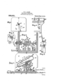
The means which I illustrate for adjusting this time element is effective also to increase the time element and to set it readily at any desired point even if it be not desired to change it from time to time. It is, therefore,'useful both to supplement the structure shown within the container for the initial time element, delicately 'determiningvthe' the same base, shaft, contact pieces and retarding mechanism may be used with difierent containers to reach any range of adjustment from a fraction of a minute to any de- The retarding mechanism of which I make use is shown in Figs. 2 and 3 where a cam 43, provided with a cam surface 44, is attached to the shaft 4 as at 45 so as to swing with it, and'during the swinging movement to engage with the roller or other bearing surface 46 which I show as mounted be: one end of a rock in the form of a rod or bolt 49 carrying adjustable weight 50 thereon.
I secure the arms 47 to-the rod '49 by means tween brackets 52 supported by the base 3.
As will be seen from the illustration, when of rivets 51 and support the rocker arm bethe leverf9 is thrown to the left It-Will carr'y I the shaft and hence thecontainer and con-- tacts with it so asto free the contact fingers 37 from the contact pieces 39 but not yet to make contact betweengthe fingers 38 and the pieces 40 for two reasons. These are, be-
cause the mercury "or other content has'not yet flowed. suffi'cient-ly toward the end 26 to over-balance the container, and because the ment.
over-balancing must also cause the lifting of the weight 50 through the cam surface 44 due to additional quantity of content in the end 26, before the container can complete 1ts movement.
The cam surface 44 can be placed at any desired place along the edge 53 and difierent cams can readily be inserted to vary this position and also to vary the extent ofhft and the speed of lift to any desired extent.
It will thus be seen that I provide for quite a number of means of quickly and inexpensively varying the time element with my mechanism, by change of the container, by variation in the extent of the cam action and by adjustment of the position of the weight. In addition to all of these I can, of course, provide the container with a filling opening, as at 54 by which the quant ty of content can be changed quickly and easll and I can change the weight 50 readily, pr viding a great variety and range of ad ust- It will further be evident that I keep the contacts where they can readily be accessible for adjustment, replacement or cleaning and that by springing 37, 37 toward 39, 39 or vice versa to a suflicient extent I cause rubbing contact to be made which automatically cleanses the contacts themselves. The same is, of course, true as to 38, 38 and 40, 40.
It will be evident that other types of container providing for the desired restricted change of balance may be made use of with out departing from the scope of my invention and that other means for introducing additional retardation may be supplied.
It will be evident that other means of re-' tardation than the weight and other means of adjustment thereof may also be made use of and that a wide variety of types of contact pieces and circuits united thereby will occur to the mechanic skilled in the art to which this appertains, all within the scope of my invention and each securing a part of the benefit thereof.
It will be evident that other means may be provided for allowing angular play between the rocking mechanism and the lever or other means by which it is rocked and that my invention may be applied to hand levers or automatically operated in connection with any other apparatus.
For the purpose of illustrating the automatic operation of a time element in the art in connection with which I have preferred to explain my, invention I show in Figs. 5 and 6 different kinds of levers which are recognized in that art, in each of which a time circuit switch is shown at 55. a
In Fig. 5 it is shown as connected to the switch or signal throwing arm 56 hand operated by means of lever 57 controlled by latch I lever 58 and operating over segment 59. In the form shown in Fig. 61 have shown these two different levers I recognize that there are various other types of levers in use both for hand and power switch and signal operation and in more or less remote connections therewith, and that my invention may be controlled automatically by any of the various forms.
While the levers shown in Figs. 5 and 6 are Well recognized in railway switch and signal operation, it may not be out of place here to state that these are the levers by which either switches or signals are thrown by hand and power respectively. In these two systems electric locking and 'releaseof this locking by electric circuit means are well known. Consequently one of my time elements can be connected so that its lever arm 9 is thrown in either direction by the movements of the lever 57 or 62, with the result that a circuit is completed by my time switch subsequent to the throwing of the lever 57 or (SQ-and any desired time after it. This circuit so completed is made to release some other lever of the system which can, therefore, not be thrown until that release and is protected from being throw-n too soon after the lever 57 or 62. The completion of the circuit by my time controlled switch might, of course, be made to lock the lever instead of releasing it should .the requirements of the service call for this action since both locking and releasing act-ion of the electric current are well known in connect-ion with the control of these levers.
Whenthe lever 9 is thrown in either direction the. container is tilted in the opposite direction from that in which it has previously sloped with resultant flow of the content toward the lower end of the container. This flow will take place rapidly or slowly according to the size of the passage between, which is a matter of initial design. In the form shown in the drawing, it will flow slowly toward the right and quickly toward the left. Because of the loose connection between'the lever and the shaft 4:, the container cannot move far enough for electrical contact to be completed until a sufiicient quantity of the content has flowed to the lower end for its weight to overbalance the rest and cause the weight of the container itself to complete the movement. In addition to. this means of retardation, I introduce a weight which must be lifted to a predetermined distance and make the effect of this weight adjustable by varying the lever arm. When enough of the fluid content of the container has flowed to the lower end for its weight to overeomeall of the re tardation'intenposed, the container will complete its movement and the cont-act fingers 37 37 or 38, 38 will complete the circuit by contact with the pieces 39, 39 or 4.0, 40 cansing a flow of current, which, in the art to which I have applied my invention, may be made to lock or release some other switch or signal throwing lever so as to prevent this and the lever by which my time controlled electrical switch has been operated from being thrown too nearly together or too far apart.
Having described my invention what I claim as new and desire to secure .by Letters Patent is:
1. In a time switch, a rocking time element whose content flows more easily in one direction than in the other, means for partially rocking said element, permitting it to continue the rocking by reason of the movement of the content, a weight and means car-- ried by the rocking element for lifting the weight during its rocking movement.
2. In a time switch,-a rocking time element, a cam carried thereby, a'weight lifted by said cam and exterior contacts engaged by the element at'the extremities of its rock-' ing movement. 4
3. In a time switch, a rocking time element, exterior contacts carried thereby, cooperating contacts engaged at'each extremity of the rocking movement andan independent element met by the time element during its rocking movement'and providing adjustable retardation overcome during the rocking movement by the operation of the time element. p
4. Ina time switch, 'a rocking timeelement having a partition therein, forming a compartment freely communicating with the rest of the element at one end and restrict edly connected with said element at the other end, a fluid therein, contacts engaged thereby and an independent exterior element met by the time element during its rocking movement and oifering adjustable resistance overconnected with said element at the other.
by said cam during the rocking movement.
6. In a time switch, a rocking time element having a partition therein, forming a compartment'freely communicating with the rest of the element at one end and restrictedly connected with said element at the other end, a fluid therein, contacts carried thereby, an element inter-posing adjustable retardation to said movement near one end and means moving with said element for overcoming the retardation.
7. In a time switch, a rocking element, a rocker arm, a weight mounted upon the rocker arm, and means carried by the element for engaging the arm to lift the weight and maintain it in raised position.
8. In a time switch, a rocker arm, a
weight thereon, a rocln'ng element, a cam carried by the element and engaging the arm and means within the element for varying its tendency in certain positions to perform its rocking function.
9. In a time switch, a fluid container, means for rocking it, exterior contacts carried by the container, a cam also carried thereby, a rocker armhaving one end engaging with the cam,- a weight adjustable along the other end of the arm and fixed contacts engaged by the movable contacts at one end of their stroke.
- WALTER P. ALLEN. Witnesses:
- WILLIAM STEELL JACKSON, WM. HARRISON Sm'rrr.
Priority Applications (1)
| Application Number | Priority Date | Filing Date | Title |
|---|---|---|---|
| US54564510A US992631A (en) | 1910-02-24 | 1910-02-24 | Time circuit-controller. |
Applications Claiming Priority (1)
| Application Number | Priority Date | Filing Date | Title |
|---|---|---|---|
| US54564510A US992631A (en) | 1910-02-24 | 1910-02-24 | Time circuit-controller. |
Publications (1)
| Publication Number | Publication Date |
|---|---|
| US992631A true US992631A (en) | 1911-05-16 |
Family
ID=3060965
Family Applications (1)
| Application Number | Title | Priority Date | Filing Date |
|---|---|---|---|
| US54564510A Expired - Lifetime US992631A (en) | 1910-02-24 | 1910-02-24 | Time circuit-controller. |
Country Status (1)
| Country | Link |
|---|---|
| US (1) | US992631A (en) |
Cited By (2)
| Publication number | Priority date | Publication date | Assignee | Title |
|---|---|---|---|---|
| US2934354A (en) * | 1956-03-21 | 1960-04-26 | Dawson Vogel Engineering Compa | Mercury switch controller apparatus for vehicle suspension |
| US3073919A (en) * | 1960-07-05 | 1963-01-15 | Mendel Brown | Lapsed timer |
-
1910
- 1910-02-24 US US54564510A patent/US992631A/en not_active Expired - Lifetime
Cited By (2)
| Publication number | Priority date | Publication date | Assignee | Title |
|---|---|---|---|---|
| US2934354A (en) * | 1956-03-21 | 1960-04-26 | Dawson Vogel Engineering Compa | Mercury switch controller apparatus for vehicle suspension |
| US3073919A (en) * | 1960-07-05 | 1963-01-15 | Mendel Brown | Lapsed timer |
Similar Documents
| Publication | Publication Date | Title |
|---|---|---|
| US992631A (en) | Time circuit-controller. | |
| US1908567A (en) | Circuit making and breaking device | |
| US1460785A (en) | Control mechanism | |
| US1559110A (en) | Motor controller | |
| US618384A (en) | Automatic weighing-machine | |
| US1157960A (en) | Time-controller. | |
| US1930435A (en) | Mercury switch | |
| US2306568A (en) | Quick breaking thermal relay | |
| US1815385A (en) | Humidifying system | |
| US1380168A (en) | Thermostatic switch | |
| US733564A (en) | Electric controller. | |
| US936329A (en) | Electrically-operated automatic switch. | |
| US1433951A (en) | Three-position tractive relay | |
| US846382A (en) | Switching mechanism. | |
| US2156684A (en) | Electrical relay | |
| US1694977A (en) | Circuit-controlling device and system employing the same | |
| US784022A (en) | Electric switch. | |
| US999578A (en) | Electric controller. | |
| US1006824A (en) | Alarm-actuating mechanism for incubators. | |
| US1093137A (en) | Electromagnetic controlling device. | |
| US1966965A (en) | Electrical relay | |
| US779447A (en) | Electric controller. | |
| US448273A (en) | Electrically-controlled valve | |
| US645103A (en) | Electric-circuit controller. | |
| US656972A (en) | Electric motor. |