US992358A - Pump. - Google Patents
Pump. Download PDFInfo
- Publication number
- US992358A US992358A US43277108A US1908432771A US992358A US 992358 A US992358 A US 992358A US 43277108 A US43277108 A US 43277108A US 1908432771 A US1908432771 A US 1908432771A US 992358 A US992358 A US 992358A
- Authority
- US
- United States
- Prior art keywords
- tube
- plunger
- pump
- water
- weight
- Prior art date
- Legal status (The legal status is an assumption and is not a legal conclusion. Google has not performed a legal analysis and makes no representation as to the accuracy of the status listed.)
- Expired - Lifetime
Links
- XLYOFNOQVPJJNP-UHFFFAOYSA-N water Substances O XLYOFNOQVPJJNP-UHFFFAOYSA-N 0.000 description 12
- 238000010276 construction Methods 0.000 description 3
- 238000004880 explosion Methods 0.000 description 1
- 239000000463 material Substances 0.000 description 1
Images
Classifications
-
- F—MECHANICAL ENGINEERING; LIGHTING; HEATING; WEAPONS; BLASTING
- F04—POSITIVE - DISPLACEMENT MACHINES FOR LIQUIDS; PUMPS FOR LIQUIDS OR ELASTIC FLUIDS
- F04B—POSITIVE-DISPLACEMENT MACHINES FOR LIQUIDS; PUMPS
- F04B53/00—Component parts, details or accessories not provided for in, or of interest apart from, groups F04B1/00 - F04B23/00 or F04B39/00 - F04B47/00
- F04B53/06—Venting
-
- Y—GENERAL TAGGING OF NEW TECHNOLOGICAL DEVELOPMENTS; GENERAL TAGGING OF CROSS-SECTIONAL TECHNOLOGIES SPANNING OVER SEVERAL SECTIONS OF THE IPC; TECHNICAL SUBJECTS COVERED BY FORMER USPC CROSS-REFERENCE ART COLLECTIONS [XRACs] AND DIGESTS
- Y10—TECHNICAL SUBJECTS COVERED BY FORMER USPC
- Y10T—TECHNICAL SUBJECTS COVERED BY FORMER US CLASSIFICATION
- Y10T74/00—Machine element or mechanism
- Y10T74/21—Elements
- Y10T74/2173—Cranks and wrist pins
- Y10T74/2183—Counterbalanced
Definitions
- pumps by counterbalancing that portion of the water column which remains after each discharge, and to provide means whereby the length of the water column is maintained even when there is some leakage of the pump valves, the devices being adapted for use in connection with drilled wells, or such as have no space outside the well tube.
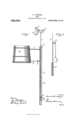
- Figure 1 is a side elevation showing the main portions of my apparatus in operative position.
- Fig. 2 is a like view illustrating a different construction.
- A represents a well tube having as usual at or near its lower end an upwardly opening valve B capable of fully closing the tube.
- the portion of the tube just above the valve serves as a barrel or cylinder in which works a plunger C, of any approved construction, provided with an upwardly opening valve D and having its rod E extending upward beyond the upper end of the tube and sliding in a suitable fixed bearing F.
- the plunger is caused to reciprocate by means of a crank G of a power shaft H driven by a wind, steam, explosion, or other engine (not shown), the crank being connected to the plunger rod by a pitman I having a swiveled or hinged union therewith.
- crank shaft is further provided with a second preferably equally eccentric crank J upon which is supported a counterweight K approximately equal in weight to a body of water sufficient to fill the tube A from the highest point reached by the plunger to the point at which water is discharged from the tube.
- This weight is preferably made up of detachable parts K so that the total weight may be adjustedfor water columns of difierent weight.
- Fig. 2 the column and plunger are shown as counterbalanced by a weight 1? suspended by a cable passing over a pulley Q, and attached at alower point to the plunger rod R in such manner that weight tends to draw the rod upward with material lateral pull.
- This form counterbalances the column, but in practical use it is a far less desirable construction than that shown in Fig. 1.
- my invention is applicable to pumps used in driven or drilled wells, as well as in wells where access may be had to the exterior of the tube, and that in fact it is in such drilled wells, often from two hundred to five hundred feet in depth, that the use of the invention is of greatest importance.
Landscapes
- Engineering & Computer Science (AREA)
- Mechanical Engineering (AREA)
- General Engineering & Computer Science (AREA)
- Reciprocating Pumps (AREA)
Description
F. 0. KANGAS.
PUMP.
APPLICATION PILnnmY 14, 1908.
Patented May 16, 1911.
s orrrfon.
FRANK OSKAR KANGAS, OF GHANNING, TEXAS, ASSIGNOR OF THREE-EIGHTH$ TO OTIS H. TWADDELL AND THREE-EIGHTHS TO SNEED H. TWADDELL, OF DALHART,
TEXAS.
PUMP.
Specification of Letters Patent.
Patented May 16, 1911.
Application filed May 14, 1908. Serial No. 432,771.
mize power and improve the working of such.
pumps by counterbalancing that portion of the water column which remains after each discharge, and to provide means whereby the length of the water column is maintained even when there is some leakage of the pump valves, the devices being adapted for use in connection with drilled wells, or such as have no space outside the well tube.
In the accompanying drawings, Figure 1 is a side elevation showing the main portions of my apparatus in operative position. Fig. 2 is a like view illustrating a different construction.
In these figures, A represents a well tube having as usual at or near its lower end an upwardly opening valve B capable of fully closing the tube. The portion of the tube just above the valve serves as a barrel or cylinder in which works a plunger C, of any approved construction, provided with an upwardly opening valve D and having its rod E extending upward beyond the upper end of the tube and sliding in a suitable fixed bearing F. The plunger is caused to reciprocate by means of a crank G of a power shaft H driven by a wind, steam, explosion, or other engine (not shown), the crank being connected to the plunger rod by a pitman I having a swiveled or hinged union therewith. The crank shaft is further provided with a second preferably equally eccentric crank J upon which is supported a counterweight K approximately equal in weight to a body of water sufficient to fill the tube A from the highest point reached by the plunger to the point at which water is discharged from the tube. This weight is preferably made up of detachable parts K so that the total weight may be adjustedfor water columns of difierent weight.
"Water raised by the pump is discharged through a conduit L into any suitable tank M.
Should there be any leakage at the valves and should the pump be out of. action for some time, the water column sometimes several hundred feet in length, might disappear leaving the heavy weight unbalanced. To avoid this result, a small pipe N leads from the tank back into the tube and is provided with a valve 0 which may be left open slightly so that the level of the water in the tube is always practically the same as in the tank, and therefore the weight and the column always balance each other.
In Fig. 2 the column and plunger are shown as counterbalanced by a weight 1? suspended by a cable passing over a pulley Q, and attached at alower point to the plunger rod R in such manner that weight tends to draw the rod upward with material lateral pull. This form counterbalances the column, but in practical use it is a far less desirable construction than that shown in Fig. 1.
' It is to be noted that my invention is applicable to pumps used in driven or drilled wells, as well as in wells where access may be had to the exterior of the tube, and that in fact it is in such drilled wells, often from two hundred to five hundred feet in depth, that the use of the invention is of greatest importance.
What I claim is:
1. The combination with a pump tube having a valve at its lower end and a plunger working in the tube above the valve, of means for counterbalancing the weight of the body of the water column in said tube, and automatic means for maintaining a constant amount of water in the tube to balance the counterweight.
2. The combination with a pump tube, or a plunger in said tube, means for reciprocating the plunger, a counterweight arranged for balancing the plunger and the main body of the water in the tube, a tank, a conduit leading from the upper part of the tube to said tank, and a small conduit leading from the tank into said tube at a point below the discharge point whereby the water in the tube being kept at the same height, the counterweight remains balanced although the lower valve should leak.
3. The combination with a pump tube having near its lower end an upwardly opening valve, and a discharge outlet near its upper end, of a plunger Working in said tube above said valve, a crank shaft provided with diametrically opposite cranks, an adjustable Weight mounted upon one of said cranks, a pitman connecting the other crank to the plunger rod to operate it, and means for automatically compensating for leakage of said upwardly opening valve. 10
In testimony whereof I affix my signature in presence of two Witnesses.
FRANK OSKAR KANGAS. lVitnesses:
O. H. TWADDELL, S. H. TWADDELL.
Copies of this patentmay be obtained for five cents each, by addressing the Commissioner of Patents, Washington, D. C.
Priority Applications (1)
| Application Number | Priority Date | Filing Date | Title |
|---|---|---|---|
| US43277108A US992358A (en) | 1908-05-14 | 1908-05-14 | Pump. |
Applications Claiming Priority (1)
| Application Number | Priority Date | Filing Date | Title |
|---|---|---|---|
| US43277108A US992358A (en) | 1908-05-14 | 1908-05-14 | Pump. |
Publications (1)
| Publication Number | Publication Date |
|---|---|
| US992358A true US992358A (en) | 1911-05-16 |
Family
ID=3060692
Family Applications (1)
| Application Number | Title | Priority Date | Filing Date |
|---|---|---|---|
| US43277108A Expired - Lifetime US992358A (en) | 1908-05-14 | 1908-05-14 | Pump. |
Country Status (1)
| Country | Link |
|---|---|
| US (1) | US992358A (en) |
-
1908
- 1908-05-14 US US43277108A patent/US992358A/en not_active Expired - Lifetime
Similar Documents
| Publication | Publication Date | Title |
|---|---|---|
| US2291499A (en) | Balancing device for pumping units | |
| US34444A (en) | Improvement in pumps for deep wells | |
| US941587A (en) | Fuel-feeding apparatus. | |
| US2953095A (en) | Acoustic deep well pump with free compression column | |
| US1881951A (en) | Pump | |
| US523240A (en) | Double-acting pump | |
| US1735193A (en) | Stuffing box | |
| US1233439A (en) | Water-elevating apparatus. | |
| US475895A (en) | Engelbert j | |
| US1272737A (en) | Pump. | |
| US1136334A (en) | Lubricator-pump. | |
| US1547895A (en) | Pump | |
| US1025554A (en) | Pump. | |
| US260501A (en) | William | |
| US259394A (en) | Deep-well pump | |
| US1026713A (en) | Gravity-pump. | |
| US385842A (en) | Attoenets | |
| US687375A (en) | Pump. | |
| US1031248A (en) | Pump. | |
| US188229A (en) | Improvement in pumps for artesian wells | |
| US1048410A (en) | Pump. | |
| US1165105A (en) | Deep-well pump. | |
| US272343A (en) | bigger | |
| US759080A (en) | Pump. | |
| US724048A (en) | Pump. |