US9920769B2 - Casing made of organic matrix composite material that facilitates the discharge of smoke - Google Patents
Casing made of organic matrix composite material that facilitates the discharge of smoke Download PDFInfo
- Publication number
- US9920769B2 US9920769B2 US15/105,756 US201415105756A US9920769B2 US 9920769 B2 US9920769 B2 US 9920769B2 US 201415105756 A US201415105756 A US 201415105756A US 9920769 B2 US9920769 B2 US 9920769B2
- Authority
- US
- United States
- Prior art keywords
- casing
- face
- structural part
- grooves
- inside face
- Prior art date
- Legal status (The legal status is an assumption and is not a legal conclusion. Google has not performed a legal analysis and makes no representation as to the accuracy of the status listed.)
- Active
Links
Images


Classifications
-
- F—MECHANICAL ENGINEERING; LIGHTING; HEATING; WEAPONS; BLASTING
- F04—POSITIVE - DISPLACEMENT MACHINES FOR LIQUIDS; PUMPS FOR LIQUIDS OR ELASTIC FLUIDS
- F04D—NON-POSITIVE-DISPLACEMENT PUMPS
- F04D29/00—Details, component parts, or accessories
- F04D29/40—Casings; Connections of working fluid
- F04D29/52—Casings; Connections of working fluid for axial pumps
- F04D29/522—Casings; Connections of working fluid for axial pumps especially adapted for elastic fluid pumps
- F04D29/526—Details of the casing section radially opposing blade tips
-
- B—PERFORMING OPERATIONS; TRANSPORTING
- B64—AIRCRAFT; AVIATION; COSMONAUTICS
- B64D—EQUIPMENT FOR FITTING IN OR TO AIRCRAFT; FLIGHT SUITS; PARACHUTES; ARRANGEMENT OR MOUNTING OF POWER PLANTS OR PROPULSION TRANSMISSIONS IN AIRCRAFT
- B64D27/00—Arrangement or mounting of power plants in aircraft; Aircraft characterised by the type or position of power plants
- B64D27/02—Aircraft characterised by the type or position of power plants
- B64D27/16—Aircraft characterised by the type or position of power plants of jet type
-
- F—MECHANICAL ENGINEERING; LIGHTING; HEATING; WEAPONS; BLASTING
- F01—MACHINES OR ENGINES IN GENERAL; ENGINE PLANTS IN GENERAL; STEAM ENGINES
- F01D—NON-POSITIVE DISPLACEMENT MACHINES OR ENGINES, e.g. STEAM TURBINES
- F01D25/00—Component parts, details, or accessories, not provided for in, or of interest apart from, other groups
- F01D25/005—Selecting particular materials
-
- F—MECHANICAL ENGINEERING; LIGHTING; HEATING; WEAPONS; BLASTING
- F01—MACHINES OR ENGINES IN GENERAL; ENGINE PLANTS IN GENERAL; STEAM ENGINES
- F01D—NON-POSITIVE DISPLACEMENT MACHINES OR ENGINES, e.g. STEAM TURBINES
- F01D25/00—Component parts, details, or accessories, not provided for in, or of interest apart from, other groups
- F01D25/24—Casings; Casing parts, e.g. diaphragms, casing fastenings
-
- F—MECHANICAL ENGINEERING; LIGHTING; HEATING; WEAPONS; BLASTING
- F02—COMBUSTION ENGINES; HOT-GAS OR COMBUSTION-PRODUCT ENGINE PLANTS
- F02C—GAS-TURBINE PLANTS; AIR INTAKES FOR JET-PROPULSION PLANTS; CONTROLLING FUEL SUPPLY IN AIR-BREATHING JET-PROPULSION PLANTS
- F02C7/00—Features, components parts, details or accessories, not provided for in, or of interest apart form groups F02C1/00 - F02C6/00; Air intakes for jet-propulsion plants
- F02C7/04—Air intakes for gas-turbine plants or jet-propulsion plants
- F02C7/05—Air intakes for gas-turbine plants or jet-propulsion plants having provisions for obviating the penetration of damaging objects or particles
-
- F—MECHANICAL ENGINEERING; LIGHTING; HEATING; WEAPONS; BLASTING
- F02—COMBUSTION ENGINES; HOT-GAS OR COMBUSTION-PRODUCT ENGINE PLANTS
- F02C—GAS-TURBINE PLANTS; AIR INTAKES FOR JET-PROPULSION PLANTS; CONTROLLING FUEL SUPPLY IN AIR-BREATHING JET-PROPULSION PLANTS
- F02C7/00—Features, components parts, details or accessories, not provided for in, or of interest apart form groups F02C1/00 - F02C6/00; Air intakes for jet-propulsion plants
- F02C7/24—Heat or noise insulation
- F02C7/25—Fire protection or prevention
-
- F—MECHANICAL ENGINEERING; LIGHTING; HEATING; WEAPONS; BLASTING
- F05—INDEXING SCHEMES RELATING TO ENGINES OR PUMPS IN VARIOUS SUBCLASSES OF CLASSES F01-F04
- F05D—INDEXING SCHEME FOR ASPECTS RELATING TO NON-POSITIVE-DISPLACEMENT MACHINES OR ENGINES, GAS-TURBINES OR JET-PROPULSION PLANTS
- F05D2300/00—Materials; Properties thereof
- F05D2300/60—Properties or characteristics given to material by treatment or manufacturing
- F05D2300/603—Composites; e.g. fibre-reinforced
-
- Y—GENERAL TAGGING OF NEW TECHNOLOGICAL DEVELOPMENTS; GENERAL TAGGING OF CROSS-SECTIONAL TECHNOLOGIES SPANNING OVER SEVERAL SECTIONS OF THE IPC; TECHNICAL SUBJECTS COVERED BY FORMER USPC CROSS-REFERENCE ART COLLECTIONS [XRACs] AND DIGESTS
- Y02—TECHNOLOGIES OR APPLICATIONS FOR MITIGATION OR ADAPTATION AGAINST CLIMATE CHANGE
- Y02T—CLIMATE CHANGE MITIGATION TECHNOLOGIES RELATED TO TRANSPORTATION
- Y02T50/00—Aeronautics or air transport
- Y02T50/60—Efficient propulsion technologies, e.g. for aircraft
-
- Y02T50/672—
Definitions
- the invention relates to gas turbine casings, and more particularly, but not exclusively, to gas turbine fan casings for aeroengines.
- the fan casing performs several functions. It defines the inlet passage for admitting air into the engine, and it supports an abradable material facing the tips of the fan blades, the abradable material generally itself being supported by a cellular structure.
- Casing such as fan casings used to be made out of metal material, but they are now made out of composite material, i.e. from a fiber preform densified by an organic matrix, thus making it possible to make parts of overall weight that is less than that of the same parts when they are made out of metal, while still presenting mechanical strength that is at least equivalent if not stronger.
- Fabricating a fan casing out of organic matrix composite material is described in particular in Document EP 1 961 923.
- a fan casing is one of the parts defining a “fire” zone in the meaning of aviation certification. In this context, it must be considered as being a fire wall between the nacelle compartment situated on the outside of the casing and the flow passage defined on the inside of the casing, and it must satisfy the associated regulatory requirements.
- the invention provides a gas turbine casing made of organic matrix composite material comprising reinforcement densified by an organic matrix, said casing defining an inside volume having on its inside face a structural part having a first face facing the inside face of the casing and an opposite second face defining a portion of the flow passage, the casing being characterized in that the face of the structural part facing the inside face of the casing includes grooves opening out directly or indirectly into the inside volume of the casing, and in that these grooves extend at least in the axial direction of the casing.
- gas resulting from degradation of the matrix of the casing in the presence of flames on the outside of the casing can be discharged into the passage, thereby avoiding disturbing extinction of the fire on the outside of the casing.
- Additional grooves may extend in a direction perpendicular to these axial first grooves.
- the grooves open out at least at one axial end of the structural part.
- the grooves stop before the axial ends of the structural part and communicate with perforations opening out into the second face of the structural part.
- the structural part is bonded to the inside face of the casing via spacer studs, thereby making it possible to have recesses or spaces between the inside face of the casing and the structural part and enabling the gas given off during fire degradation of the matrix of the casing to be discharged into the passage.
- the inside face of the casing includes grooves that open out beyond the structural part.
- the structural part comprises a cellular structure facing the inside face of the casing. Under such circumstances, the presence of recesses between the structural part and the inside space of the casing enables the gas given off during degradation of the matrix of the casing to pass through the cellular structure in order to be discharged into the passage.
- the structural part may also include a layer of abradable coating supported by the cellular structure.
- the grooves may include gutters, e.g. made of a fiber texture consolidated by a matrix. This serves to seal the cellular structure in zones where it is no longer in contact with the wall of the casing.
- the structural part comprises a cellular structure facing the inside face of the casing, a skin closing the cells of the cellular structure beside the face of said cellular structure that is opposite from its face facing the inside face of the casing, the walls of the cells of the cellular structure including at least one perforation, the skin further including perforations opening out into the inside volume of the casing.
- the invention also provides a gas turbine aeroengine having a fan retention casing of the invention, and an aircraft including one or more such engines.
- FIGS. 1A and 1B are respectively a perspective view and a section view of a prior art aeroengine fan casing
- FIG. 2A is a perspective view of a structural part in accordance with an embodiment of the invention.
- FIG. 2B is a section view of an organic matrix composite material casing fitted with the structural part of FIG. 2A ;
- FIG. 3 is a perspective view of a structural part in accordance with an embodiment of the invention.
- FIG. 4A is a perspective view of a structural part in accordance with an embodiment of the invention.
- FIG. 4B is a section view of an organic matrix composite material casing fitted with the structural part of FIG. 4A ;
- FIG. 5A is a section view of an organic matrix composite material casing fitted with the structural part in accordance with an embodiment of the invention.
- FIG. 5B is a perspective view of the FIG. 5A structural part.
- FIG. 6 is a section view of an organic matrix composite material casing fitted with a structure in accordance with an embodiment of the invention.
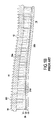
- FIG. 7 is a section view of an organic matrix composite material casing fitted with a structure in accordance with an embodiment of the invention in which the casing has a groove.
- the invention applies in general manner to any organic matrix composite material casing for a gas turbine and having on its inside face at least one structural part.
- the invention is described below in the context of its application to a fan casing of a gas turbine aeroengine.
- Such an engine comprises from upstream to downstream in the gas stream flow direction: a fan 1 arranged at the inlet of the engine; a compressor 2 ; a combustion chamber 3 ; a high pressure turbine 4 ; and a low pressure turbine 5 .
- the engine is housed inside a casing made up of a plurality of portions corresponding to the various elements of the engine.
- the fan 1 is surrounded by a fan casing 10 .
- FIG. 1B shows the profile of the fan casing 10 , which is made of organic matrix composite material, i.e. from fiber reinforcement, e.g. made of carbon, glass, aramid, or ceramic fibers, and densified by a polymer matrix, e.g. of epoxy, bismaleimide, or polyimide. Fabricating such a casing is described in particular in Document EP 1 961 923.
- the inside face 11 of the casing 10 is provided with a structural part 20 made up of a cellular structure 21 and a layer of abradable material 23 fastened to the cellular structure by a skin 22 , e.g. constituted by a layer of resin, and serving also to close the bottom portions of the cells 210 of the cellular structure 21 , with the top portions of the cells being closed by the inside face 11 of the casing with which they are in contact.
- the structural part 20 comprises a first face 20 a facing the inside face 11 of the casing 10 , with the face 20 a in this example corresponding to the high portions of the cells 210 of the cellular structure 21 .
- the structural part has a second face 20 b opposite from its face 20 a and of shape that defines a portion of the flow passage 14 .
- a casing 100 similar to the above-described casing 10 has on its inside face 101 a structural part 120 that differs from the above-described structural part 20 in that it includes grooves or corridors 130 in its first face 120 a facing the inside face 101 of the casing 100 , which grooves or corridors 130 are formed in the walls 1211 of the cells 1210 of the cellular structure 121 , the grooves 130 extending in a direction parallel to the axial direction of the casing 100 .
- the second face 120 b opposite from the face 120 a is constituted by the layer of abradable material 123 that is fastened to the cellular structure 121 via the skin 122 .
- This second face 120 b defines a portion of the flow passage 102 .
- the grooves 130 enable the gas given off (arrows GD in FIG. 2B ) during degradation of the organic matrix of the material of the casing to flow towards the downstream portion of the part 120 so as to be discharged via perforations 140 , as shown in FIG. 2B .
- the perforations 140 are present in the layer of abradable material 123 at the downstream end of the part 120 , and they enable the gas flowing in the grooves 130 to be discharged into the passage 102 situated in the inside volume of the casing 100 .
- the grooves 130 comprise gutters 131 made of fiber texture, e.g. made of carbon fibers, consolidated by a matrix, e.g. an epoxy matrix.
- the gutters 131 may be made by using a fiber texture that has been pre-impregnated with a precursor resin for the matrix and that is shaped in the grooves so as to form a web 131 a of the gutter from which there extend two gutter flanges or side walls 131 b and 131 c .
- the gutters 131 serve to seal the cellular structure in zones where it is no longer in contact with the wall of the casing, and they thus avoid allowing any moisture to penetrate into the cells of the cellular structure.
- the structural part 120 also has additional grooves 150 in its face 120 a that extends perpendicularly relative to the grooves 130 , which themselves extend in the axial direction of the casing 100 .
- Degradation gas from the casing 100 can thus flow both in the grooves 130 and in the grooves 150 so as to be discharged via the perforations 140 , i.e. into the flow passage situated in the inside volume of the casing 100 .
- the grooves 130 and 150 comprise respective gutters 131 and 151 that are formed by a fiber texture, e.g. made of carbon fibers consolidated by a matrix, e.g. an epoxy matrix.
- the gutters 131 and 151 may be made using a fiber texture that has been pre-impregnated with a resin precursor for the matrix and that is shaped in the grooves so as to form respective gutter webs 131 a and 151 a , from which there extend respective pairs of side walls 131 b & 131 c and 151 b & 151 c .
- the gutters 131 and 151 serve to seal the cellular structure in zones where it is no longer in contact with the wall of the casing, and they thus avoid allowing any moisture to penetrate into the cells of the cellular structure.
- a casing 200 similar to the above-described casing 10 has a structural part 220 on its inside face 201 that differs from the above-described structural part 20 in that it includes grooves or corridors 230 in its first face 220 a facing the inside face 201 of the casing 200 , which grooves or corridors 230 are formed in the walls 2211 of the cells 2210 of the cellular structure 221 , the grooves 230 extending in a direction parallel to the axial direction of the casing 100 .
- the second face 220 b opposite from the face 220 a is constituted by the layer of abradable material 223 that is fastened to the cellular structure 221 via the skin 222 .
- This second face 220 b defines a portion of the flow passage 202 .
- the grooves 230 enable the gas given off (arrows GD in FIG. 4B ) during degradation of the organic matrix of the material of the casing to flow towards the downstream portion of the part 220 so as to be discharged via openings 240 formed at the downstream end 230 b of the grooves 230 , the upstream ends 230 a of the grooves 230 being closed.
- the degradation gas flowing in the grooves 230 is then discharged into the passage 202 situated in the inside volume of the casing 200 .
- the grooves 230 comprise gutters 231 that are made of a fiber texture, e.g. of carbon fibers consolidated by a matrix, e.g.
- the gutters 231 may be made by using a fiber texture that has been pre-impregnated with a resin precursor for the matrix that is shaped in the grooves in order to form a gutter web 231 a from which there extend two side walls 231 b and 231 c .
- the gutters 231 serve to seal the cellular structure in the zone where it is no longer in contact with the wall of the casing, and thus avoid allowing any moisture to penetrate into the cells of the cellular structure, in particular via the openings 240 .
- the cells present in the vicinity of the grooves 230 may be densified with an intumescent adhesive or a potting resin.
- a casing 300 similar to the above-described casing 10 has a structural part 320 on its inside face 301 that differs from the above-described structural part 20 in that each of the walls 3211 of the cells 3210 of the cellular structure 321 includes one or more perforations 3212 .
- the second face 320 b opposite from the face 320 a and constituted by the layer of abradable material 323 defines a portion of the flow passage 302 .
- the perforations 3212 enable the gas given off (arrows GD in FIG.
- the perforations 340 are present in the skin 322 and the abradable material layer 323 at the downstream end of the part 320 , and they enable the gas flowing through the perforations 3212 formed in the cells 3210 to be discharged into the passage situated in the inside volume of the casing 300 .
- the perforations are made at the downstream end of the structural part. Nevertheless, perforations could equally well be made at other locations in the structural part.
- a casing 400 includes beside its inside face 401 a structural part 420 that is constituted by a cellular structure 421 and a layer of abradable material 423 fastened on the cellular structure by a first skin 422 , e.g. made of carbon plies, that also serves to close the bottom portions of the cells 4210 of the cellular structure 421 , which cells are closed in their top portions by a second skin 424 , e.g. formed by carbon plies.
- the structural part 420 has a first face 420 a facing the inside face 401 of the casing 410 , the face 420 a in this example corresponding to the top portion of the cells of the cellular structure 421 .
- the structural part has a second face 420 b opposite from the face 420 a of shape that defines a portion of the flow passage 402 .
- the structural part 420 is fastened to the casing via spacer studs 430 that are adhesively bonded firstly to the inside face 401 of the casing 400 and secondly to the face 420 a of the part 420 , which in this example is constituted by the second skin 424 .
- the spacer studs 430 are preferably adjustable in height so as to control clearances and interaction with the tips of the turbine blades.
- a corridor or recess 430 is formed between the face 420 a of the part 420 and the inside face 401 of the casing 400 , thus enabling the gas give off (arrows GD in FIG. 6 ) during degradation of the organic matrix of the casing material to flow towards the downstream portion of the part 420 in order to be discharged into the passage 402 .
- the inside face of the casing includes grooves that open out beyond the structural part. This embodiment may optionally be combined with the other embodiments described above.
Landscapes
- Engineering & Computer Science (AREA)
- Chemical & Material Sciences (AREA)
- Combustion & Propulsion (AREA)
- Mechanical Engineering (AREA)
- General Engineering & Computer Science (AREA)
- Materials Engineering (AREA)
- Aviation & Aerospace Engineering (AREA)
- Structures Of Non-Positive Displacement Pumps (AREA)
- Cylinder Crankcases Of Internal Combustion Engines (AREA)
Abstract
Description
Claims (9)
Applications Claiming Priority (3)
| Application Number | Priority Date | Filing Date | Title |
|---|---|---|---|
| FR1363213 | 2013-12-20 | ||
| FR1363213A FR3015593B1 (en) | 2013-12-20 | 2013-12-20 | CARRIER IN COMPOSITE MATRIX WITH ORGANIC MATRIX FOR THE EVACUATION OF SMOKE |
| PCT/FR2014/053397 WO2015092280A1 (en) | 2013-12-20 | 2014-12-17 | Housing made from an organic-matrix composite material promoting the discharge of smoke |
Publications (2)
| Publication Number | Publication Date |
|---|---|
| US20170023013A1 US20170023013A1 (en) | 2017-01-26 |
| US9920769B2 true US9920769B2 (en) | 2018-03-20 |
Family
ID=50137933
Family Applications (1)
| Application Number | Title | Priority Date | Filing Date |
|---|---|---|---|
| US15/105,756 Active US9920769B2 (en) | 2013-12-20 | 2014-12-17 | Casing made of organic matrix composite material that facilitates the discharge of smoke |
Country Status (9)
| Country | Link |
|---|---|
| US (1) | US9920769B2 (en) |
| EP (1) | EP3084177B1 (en) |
| JP (1) | JP6538698B2 (en) |
| CN (1) | CN105874185B (en) |
| BR (1) | BR112016014210B1 (en) |
| CA (1) | CA2933777C (en) |
| FR (1) | FR3015593B1 (en) |
| RU (1) | RU2671609C1 (en) |
| WO (1) | WO2015092280A1 (en) |
Families Citing this family (4)
| Publication number | Priority date | Publication date | Assignee | Title |
|---|---|---|---|---|
| EP3720698B1 (en) * | 2017-12-06 | 2022-10-19 | Safran Aircraft Engines | Coating with property gradient for inner wall of turbomachine |
| CN114542516B (en) * | 2020-11-26 | 2024-08-30 | 中国航发商用航空发动机有限责任公司 | Composite material casing and manufacturing method thereof |
| US11661855B2 (en) * | 2021-10-25 | 2023-05-30 | Raytheon Technologies Corporation | Low density hybrid knife seal |
| FR3145746A1 (en) * | 2023-02-14 | 2024-08-16 | Airbus Operations | PROPELLER ASSEMBLY FOR AIRCRAFT |
Citations (7)
| Publication number | Priority date | Publication date | Assignee | Title |
|---|---|---|---|---|
| US5308225A (en) * | 1991-01-30 | 1994-05-03 | United Technologies Corporation | Rotor case treatment |
| FR2698910A1 (en) | 1992-12-04 | 1994-06-10 | Grumman Aerospace Corp | One-piece acoustic drum at the entrance of an engine. |
| US6053696A (en) * | 1998-05-29 | 2000-04-25 | Pratt & Whitney Canada Inc. | Impact resistant composite shell for gas turbine engine fan case |
| GB2406615A (en) | 2003-10-03 | 2005-04-06 | Rolls Royce Plc | Combined gas turbine engine blade containment assembly and acoustic treatment |
| EP1961923A2 (en) | 2007-02-23 | 2008-08-27 | Snecma | Method of producing a gas turbine casing from a composite material and casing thus obtained. |
| WO2012076876A1 (en) | 2010-12-07 | 2012-06-14 | Gkn Aerospace Services Limited | Fire-protected composite structure |
| FR2976974A1 (en) | 2011-06-24 | 2012-12-28 | Safran | DEVICE FOR ASSEMBLING ACOUSTIC PANELS OF A TURBOMACHINE NACELLE |
Family Cites Families (8)
| Publication number | Priority date | Publication date | Assignee | Title |
|---|---|---|---|---|
| GB1499882A (en) * | 1975-02-14 | 1978-02-01 | Rolls Royce | Sound attenuating structure |
| FR2691923B1 (en) * | 1992-06-04 | 1994-09-09 | Europ Propulsion | Honeycomb structure in thermostructural composite material and its manufacturing process. |
| US5336044A (en) * | 1993-08-06 | 1994-08-09 | General Electric Company | Blade containment system and method |
| RU2260703C2 (en) * | 2003-11-18 | 2005-09-20 | Открытое акционерное общество "Авиадвигатель" | Gas-turbine engine duct noise-absorbing structure |
| FR2903734B1 (en) * | 2006-07-12 | 2008-09-12 | Airbus France Sas | TURBOMOTEUR FOR AIRCRAFT. |
| FR2968910A1 (en) * | 2010-12-17 | 2012-06-22 | Michel Daniel Coudret | Bedding accessory for transforming two beds into one bed for two persons, has mattress with fabric fixed at its base and shock absorber fixed at its center by fixed and non-fixed straps and clamps for blocking footboards |
| FR2975735A1 (en) * | 2011-05-27 | 2012-11-30 | Snecma | TURBOMACHINE BLOWER CASING AND METHOD FOR MANUFACTURING THE SAME |
| US9200531B2 (en) * | 2012-01-31 | 2015-12-01 | United Technologies Corporation | Fan case rub system, components, and their manufacture |
-
2013
- 2013-12-20 FR FR1363213A patent/FR3015593B1/en active Active
-
2014
- 2014-12-17 CA CA2933777A patent/CA2933777C/en active Active
- 2014-12-17 JP JP2016541399A patent/JP6538698B2/en active Active
- 2014-12-17 EP EP14830817.4A patent/EP3084177B1/en active Active
- 2014-12-17 RU RU2016129277A patent/RU2671609C1/en active
- 2014-12-17 US US15/105,756 patent/US9920769B2/en active Active
- 2014-12-17 WO PCT/FR2014/053397 patent/WO2015092280A1/en not_active Ceased
- 2014-12-17 BR BR112016014210-1A patent/BR112016014210B1/en active IP Right Grant
- 2014-12-17 CN CN201480069825.7A patent/CN105874185B/en active Active
Patent Citations (7)
| Publication number | Priority date | Publication date | Assignee | Title |
|---|---|---|---|---|
| US5308225A (en) * | 1991-01-30 | 1994-05-03 | United Technologies Corporation | Rotor case treatment |
| FR2698910A1 (en) | 1992-12-04 | 1994-06-10 | Grumman Aerospace Corp | One-piece acoustic drum at the entrance of an engine. |
| US6053696A (en) * | 1998-05-29 | 2000-04-25 | Pratt & Whitney Canada Inc. | Impact resistant composite shell for gas turbine engine fan case |
| GB2406615A (en) | 2003-10-03 | 2005-04-06 | Rolls Royce Plc | Combined gas turbine engine blade containment assembly and acoustic treatment |
| EP1961923A2 (en) | 2007-02-23 | 2008-08-27 | Snecma | Method of producing a gas turbine casing from a composite material and casing thus obtained. |
| WO2012076876A1 (en) | 2010-12-07 | 2012-06-14 | Gkn Aerospace Services Limited | Fire-protected composite structure |
| FR2976974A1 (en) | 2011-06-24 | 2012-12-28 | Safran | DEVICE FOR ASSEMBLING ACOUSTIC PANELS OF A TURBOMACHINE NACELLE |
Non-Patent Citations (2)
| Title |
|---|
| International Preliminary Report on Patentability and the Written Opinion of the International Searching Authority as issued in International Patent Application No. PCT/FR2014/053397, dated Jun. 21, 2016. |
| International Search Report as issued in International Patent Application No. PCT/FR2014/053397, dated Apr. 16, 2015. |
Also Published As
| Publication number | Publication date |
|---|---|
| RU2671609C1 (en) | 2018-11-02 |
| CN105874185A (en) | 2016-08-17 |
| EP3084177B1 (en) | 2018-02-07 |
| JP2017503953A (en) | 2017-02-02 |
| WO2015092280A1 (en) | 2015-06-25 |
| US20170023013A1 (en) | 2017-01-26 |
| RU2016129277A (en) | 2018-01-25 |
| BR112016014210A2 (en) | 2017-08-08 |
| FR3015593B1 (en) | 2018-09-07 |
| CA2933777A1 (en) | 2015-06-25 |
| BR112016014210B1 (en) | 2021-08-03 |
| CN105874185B (en) | 2018-03-27 |
| CA2933777C (en) | 2021-12-07 |
| FR3015593A1 (en) | 2015-06-26 |
| JP6538698B2 (en) | 2019-07-03 |
| EP3084177A1 (en) | 2016-10-26 |
Similar Documents
| Publication | Publication Date | Title |
|---|---|---|
| US9920769B2 (en) | Casing made of organic matrix composite material that facilitates the discharge of smoke | |
| US10876479B2 (en) | Acoustic liner having multiple layers | |
| US10280839B2 (en) | Acoustic treatment panel | |
| KR101723323B1 (en) | Gas turbine silencer, and gas turbine provided with same | |
| US9399951B2 (en) | Modular louver system | |
| US20180291841A1 (en) | Intermediate casing hub for an aircraft turbojet engine including a composite outlet pipe | |
| RU2422331C2 (en) | Section of gondola air intake edge with electric ice protection and acoustic absorption zone | |
| US9630702B2 (en) | Noise attenuation for an open rotor aircraft propulsion system | |
| US20080185217A1 (en) | Device for silencing a helicopter gas turbine engine and engine thus obtained | |
| US7886543B2 (en) | Central body for a turbojet exhaust channel, turbojet | |
| CN102597477A (en) | A noise attenuation panel and a gas turbine component comprising a noise attenuation panel | |
| EP1857655A3 (en) | A liner panel | |
| US11932399B2 (en) | Expandable cellular system for a sandwich panel | |
| US20200049074A1 (en) | Acoustic panel and method for making the same | |
| CN104114817A (en) | Cellular acoustic structure for a turbojet engine and turbojet engine incorporating at least one such structure | |
| EP2474474A2 (en) | Arrangement for maintaining flow to an air inlet of an auxiliary power unit assembly | |
| CA3068140A1 (en) | Acoustic structure for gas turbine engine | |
| US20180135515A1 (en) | System and method for fluid acoustic treatment | |
| US9039352B2 (en) | Sound attenuating chimney element for a turbomachine system | |
| US11873763B2 (en) | Optimised discharge line grid and optimized discharge valve | |
| US20250282466A1 (en) | Aircraft acoustic panel with integrated fire-resistant material | |
| CN106121484A (en) | Novel environment friendly fireproof door frame | |
| CA2852324A1 (en) | Acoustic structure for a gas turbine engine |
Legal Events
| Date | Code | Title | Description |
|---|---|---|---|
| AS | Assignment |
Owner name: SNECMA, FRANCE Free format text: ASSIGNMENT OF ASSIGNORS INTEREST;ASSIGNORS:QUILLENT, HELENE;LANGEVIN, THOMAS;MOURLAN, JEAN-PIERRE ANDRE JOSEPH;AND OTHERS;SIGNING DATES FROM 20150121 TO 20150208;REEL/FRAME:038941/0888 |
|
| STCF | Information on status: patent grant |
Free format text: PATENTED CASE |
|
| AS | Assignment |
Owner name: SAFRAN AIRCRAFT ENGINES, FRANCE Free format text: CHANGE OF NAME;ASSIGNOR:SNECMA;REEL/FRAME:046479/0807 Effective date: 20160803 |
|
| AS | Assignment |
Owner name: SAFRAN AIRCRAFT ENGINES, FRANCE Free format text: CORRECTIVE ASSIGNMENT TO CORRECT THE COVER SHEET TO REMOVE APPLICATION NOS. 10250419, 10786507, 10786409, 12416418, 12531115, 12996294, 12094637 12416422 PREVIOUSLY RECORDED ON REEL 046479 FRAME 0807. ASSIGNOR(S) HEREBY CONFIRMS THE CHANGE OF NAME;ASSIGNOR:SNECMA;REEL/FRAME:046939/0336 Effective date: 20160803 |
|
| MAFP | Maintenance fee payment |
Free format text: PAYMENT OF MAINTENANCE FEE, 4TH YEAR, LARGE ENTITY (ORIGINAL EVENT CODE: M1551); ENTITY STATUS OF PATENT OWNER: LARGE ENTITY Year of fee payment: 4 |
|
| MAFP | Maintenance fee payment |
Free format text: PAYMENT OF MAINTENANCE FEE, 8TH YEAR, LARGE ENTITY (ORIGINAL EVENT CODE: M1552); ENTITY STATUS OF PATENT OWNER: LARGE ENTITY Year of fee payment: 8 |