US991973A - Elevator signaling apparatus. - Google Patents
Elevator signaling apparatus. Download PDFInfo
- Publication number
- US991973A US991973A US41763608A US1908417636A US991973A US 991973 A US991973 A US 991973A US 41763608 A US41763608 A US 41763608A US 1908417636 A US1908417636 A US 1908417636A US 991973 A US991973 A US 991973A
- Authority
- US
- United States
- Prior art keywords
- car
- signal
- operated
- controller
- passengers
- Prior art date
- Legal status (The legal status is an assumption and is not a legal conclusion. Google has not performed a legal analysis and makes no representation as to the accuracy of the status listed.)
- Expired - Lifetime
Links
- 230000011664 signaling Effects 0.000 title description 23
- 230000007246 mechanism Effects 0.000 description 67
- 230000000007 visual effect Effects 0.000 description 13
- 238000010276 construction Methods 0.000 description 9
- QSHDDOUJBYECFT-UHFFFAOYSA-N mercury Chemical compound [Hg] QSHDDOUJBYECFT-UHFFFAOYSA-N 0.000 description 5
- 229910052753 mercury Inorganic materials 0.000 description 5
- 230000009916 joint effect Effects 0.000 description 3
- 238000009877 rendering Methods 0.000 description 3
- 239000011435 rock Substances 0.000 description 3
- FPIPGXGPPPQFEQ-OVSJKPMPSA-N all-trans-retinol Chemical compound OC\C=C(/C)\C=C\C=C(/C)\C=C\C1=C(C)CCCC1(C)C FPIPGXGPPPQFEQ-OVSJKPMPSA-N 0.000 description 2
- 210000005069 ears Anatomy 0.000 description 2
- IJJWOSAXNHWBPR-HUBLWGQQSA-N 5-[(3as,4s,6ar)-2-oxo-1,3,3a,4,6,6a-hexahydrothieno[3,4-d]imidazol-4-yl]-n-(6-hydrazinyl-6-oxohexyl)pentanamide Chemical compound N1C(=O)N[C@@H]2[C@H](CCCCC(=O)NCCCCCC(=O)NN)SC[C@@H]21 IJJWOSAXNHWBPR-HUBLWGQQSA-N 0.000 description 1
- 235000010724 Wisteria floribunda Nutrition 0.000 description 1
- 239000011717 all-trans-retinol Substances 0.000 description 1
- 235000019169 all-trans-retinol Nutrition 0.000 description 1
- KNHUKKLJHYUCFP-UHFFFAOYSA-N clofibrate Chemical compound CCOC(=O)C(C)(C)OC1=CC=C(Cl)C=C1 KNHUKKLJHYUCFP-UHFFFAOYSA-N 0.000 description 1
- 230000004048 modification Effects 0.000 description 1
- 238000012986 modification Methods 0.000 description 1
Images

Classifications
-
- B—PERFORMING OPERATIONS; TRANSPORTING
- B66—HOISTING; LIFTING; HAULING
- B66B—ELEVATORS; ESCALATORS OR MOVING WALKWAYS
- B66B1/00—Control systems of elevators in general
- B66B1/34—Details, e.g. call counting devices, data transmission from car to control system, devices giving information to the control system
- B66B1/46—Adaptations of switches or switchgear
- B66B1/468—Call registering systems
Definitions
- My invention relates to an elevator signaling apparatus, and my object is to provide a construction bywliich an operator of any one of a plurality of cars may run by a floorA Where an intending passenger has operated a device, such as the ordinary push-Y button, for the purpose of signaling the car to stop, and still leave the parts or circuits in condition to operate the signal of the next following car, so that the next following ear will receive the signal to stop at suoli floor.
- a device such as the ordinary push-Y button
- (')iie of the objects of ⁇ my invention is to provide means under the control of, and operable by, the operator of a car by which he may reset the push-bi .iii-operated nicchanisiii of the other car or cars of the bank of elevators in the same condition that it would be if tlic floor lnish-button lny ⁇ i" been again pushed by the intending passi'iiigci, and so leave the n'ieehanisi'n in condition such that the next following ⁇ ca r will receive the signal.
- FIG. 1 I have shown diagrammatically my invention as such as represented in the a construction applied to Bowne Patent 850,018, and from the following description it will be evident to any in the art how n tually adapted to consider that the tion in Fig. 1 indi with the elevator tion and. feature clearly than detai anism.
- the iiieaiis fordisplayiiig the signa ls prei" ⁇ erabl'v comprises mechanism which is ed to be set in one position by ot' a door push-b adapt# the operation iitton and also a commutator which determines the time 'when tli signal sha] has l en operated my invention ill'i drawings such mechanism set by the bitton on the fourth pivoted arms 9 and 10, gether with pivoted dctents 11 and l be given after the push-butterY andin the eiiiboiliiiieiit of .istrated in Fig. 1 of the push- ⁇ loor comprises two one for each car, to-
- a cominutator for commuting o'r successively closing or opening a series of electric circuits, one part of which is moved correspondingly with the car and the other part or portions of which are relatively stationary.
- the commutator renders the signals inoperative except when the car is approaching and is adjacent the Hoor on which a passengers controller has been operated and 4comprises suitable fixed contacts, and brushes moved correspondingly wit-h the movement of the elevator, as is common, but preferably much slower. I have not shown the connection bet-ween the moving brushes and the hoisting mechanism of the car, because it would complicate the drawings and it is evident to any mechanic skilled in the art.
- the fixed contacts of the commutator for car 2 are indicated by 24 and 26, andthe moving brush as 28.
- the commutator for car 1 consists of the fixed contacts 31 and 33, and the'moving brush 34. I have also provided in the present instance fixed contacts 25, 27, 30 and 32, and moving brushes 29 and 35, which I have lfor convenience embodied as parts of the commutator, although thisis not necessary in all cases.
- the restoring mechanism for restoring the arm to normal condition may, if desiredbe a projection 42 on the endo't the arn'rwhich will be engaged by a l'noving.portion 'of the f'xnnmntator, .such as Inni-5h28, ⁇ which will both detents 1,1 and 17 drop baci.r because of their over/weighted ends to the normal position under the projections 15 and 58, thus restoring the parts to normal condition.
- the pin 35) on arm 9 will strike the bottom of the slot4l),.and
- the operation of the commutator of car 1 is substantially the same as just described with reference to the arm 10 and the signal 6 inthe car.
- the arm 10 will be similarly restored by brush 34 and as the top of slot 40 will strike pin ⁇ 39, it will, preferably, also res'tore arm
- transfer means which is in part carried by the car and operablevby the operator thereof and which Vis adapted to cause the pushbutton-operated arm 10 of the other following car 1 to be left in the set position after car 2 has restored arm 9 to normal position.
- This transfer means in the present embodiment of my,invention,eomprises s transfer button or switch 43 in car 2, a moving brush 29 of the commutator, and the fixed commutator contact 25. The brush 29 strikes the -contact 25 just after'brush 28 has raised arm 9 and passed out of engagement with the same.
- switch 43 If, therefore, switch 43, he will close a circuit from battery 36, through such switch, brush 29 and contact 25, and from there through setting magnets 13 and 14 in series, and back to the battery, thus drawing detents 11 and 12 to the position shownand .resetting arm 10 (and preferably arm 9 also) in the set position, which is the same as would result if the push-button 8 were again pushed.. This will obviously leave the parts in c011- dition such that when the connnutator brush 34 of'car 1 strikes contact- 31, the car 1 will receive the signal to stop at the floor'.
- the brush 34 will then, thecar passes on, strike the end 44 of arm 10, and the transferred signal will be restored to normal condition, or, if desired, the operator of car ⁇ 1 may press his transfer button 46 when brush 35 strikes cont-act '30 and pass on, resetting arm t) in the position shown.
- the mechanism for operating the signals when the' car is approaching Hoor 3 is substantially the same as abovey described, comprising arms 5Q, 5l, the magnets 52, 53 which are operated by the push-button 7 or transfer button 46 to ⁇ withdraw the dei tents 54, 55, the magnets 56 and 57 for Withdrawing the detents 58, 59, and 4the mercry pots and fingers 60, 61 and 62, 63. v
- Fig. 2 1 have, for the purposes o1 illustration merely, shown a nloditicatioii of my invention which is adapted to be used with, for example, the construction shown in the Smalley & Reiners patent, heretofore-mentioned.
- this construction 7() and 71 are the two cars, 72 and 73 the floor pushbuttons, 74 and 75 the transfer l..u.1ttons,iand 70 to 87 the fixed, and Si) to 911 the moving, parts of the ctm'nnutators.
- '-11 is ablock on lever 10 which rests on top of the armature 1S. 17 is the magnet which moves said armature.
- ttl and 1S are fixed pivots on which the armsl 9 and 10 rock.
- (54 and (55 are the similar lixed pivots for the levers 50 and 51.
- 125 and 120 are insulating portions of the levers i) and which serve to insulate the pins 1f.) and 20 from the rest of the arms.
- 1,250 is a stop pin, movable with lbrush 2S, to normally hold the moving brush28 from moving bcyon d its position shown under impulso of spring 127. 131 is a similar stop for thc brush 3 4.
- 105 ⁇ and 10G are suitable sources of electron'lotive torce, such as a dynamo and a battery, i'esl'iectively.
- an electric signaling apparatus for elevators in combination, a pair of cars, an electrically-operated signal for each car, means for operating said signals comprising ⁇ a passengers controller located at a floor and mechanism set byl the operation of said passenge1"scontroller, signal transfer means in part carried by each car and operable by the operator of the car for settingsaid passengers-controller-operated mechanism in posltion such that the signal of the other car will be operated, and means for restoring said mechanism to' normal condition whereby the transferred signal is restored to normal condition, said transfer means comprising mechanism rendering said transfer means incapable of controlling 'said passengers-controller-operated mechanism except when the car from which the transfer means has been operated is adjacent the vfloor on which said passengers controller is located.
- a palr of cars a visual signal carried by each cal-,means for displaying said signals comprising a passengers-,controller locatedA at a floor, a commutator for and operated b each car and mechanism set by the operatlon of said passengers-controller, said commutator and mechanism acting conjointly to determine the time when a signal shall be given, signal transfer means inpart carried by: each car and operable by the operator of the car for setting said passengers-controller-operated mechanism in position such that the signal of the other car will be displayed, and means for restoring said mechanism to normal condit' n whereby the transferred signal is restored to normal condition.
- a visual signal for each car means for Adisplaying sald slgnals comprlsmg a passengers controller located at a floor and mechanism for each car set by' the operation of ⁇ said passengers-controller, signal transfer means in part carried by each car and operable by the operator of each car for setting said passengcs-controller-operated mecha- A fuji nism which corresponds to the other car in position such that the signal ofthe other car Will be displayed, and means y said mechanism to normal condition whereby the transferred signal is restored to normal condition, said transfer means compriswhich said passengers-controller is located.
- signals may be operated and comprising a passengers-controller located at a floor and a commutator for each car operated correspondingly with the movement of such car for restoring v and mechanism set by the passengers-controller, restoring means operated by each car for restoring to normal condition the mechanism so set by said passengers-controller, and signal transfer means in part carried by each car and operable by the operator of the car for resetting the said passengers-controller-operated mechanism.
- an electric signaling apparatus for elevators the combination of a air of cars and floors, a visual signal carrled by each car, means for determining the time when said signals may be displayed and cornprising a passengers-controller located at each floor, a commutator for each car operated correspondingly with the movement of such ⁇ car andV mechanism corresponding to each floor set by said passengers-controller, restoring means operated by each car for restoring to normal condition the mechanism so set by said p assengers-controllers, and signal transfer means inpart carried by each car and operable by the operator of the car for resetting either ofthe said passengers-controller-operated mechanisms.
- an electric signaling apparatus for elevators the combination of a air of cars and floors, a visual signal carrled by each car, means for determining the'time when -said signals may be displayed and comprising a passengers'-controller located at each floor, a commutator for each car operated correspondingly with the movement of such car and mechanism corresponding to each floor set by said passengers-controller, sald mechanism so set being common to both cars,
- means for determininnv the time ⁇ when said signals may be displayed comprising a jJassengeWscontroller located at a floor and a commutator for each car operated eorrespol'nlingly with the movement of sneh car and mecha nism tor each car set by the passengers controller, restoring means operated hy each ear for restoringto normat condition the mechanisms so set by said jmssengers-con- 'trollen and signal transfer means in part carried by each car and operable by the operator of'the car for resetting the said passengers-controller-operated mechanism which corresponds to the other car.
- an electric signalii'ig apparatus for elevators the combination of a pair of ears, an electricaily-operated signal for each car, means for operating,r said signals coi'nprising, and operating by the joint action of, a con'imutator t'or and operated by each car correspondingly to the n'iovement thereof and mechanism to be set, signal transfer means in parti carried by each car and operable by the operator of the car for setting the said'mecl'iaiiism in position such that the signal of said other car will be operated, and restoring means for restoring said mechanism to normal condition.
- an electric sigmaling4 apparatus for elevators the combination of a pair of cars, a visual signal carried by each ear, means for displaying said signals comprisinf, and operating by the joint action of, 'i commutator for and operated by each car corresl'ionclingly to the movement thereof and mechanism to be set, signal transfer means in part carried by each car and operable Ly the ojierator of the. ear for setting the said n'ieehanisni in position such that the signal ot. said other car will be displayed, and restoring means for restoringsaid meeh-y anism to normal condition.
- an electric Signaling apparatus for elevators the combination of a pair of cars, a visual signal for each car, means for determining the time when a signal can be displayed and comprising a commutator opera ted by each car and a passenge'fscontrolter located at a floor and mechanism for each car adapted to be set; by said passenger-scontroller, restoring means operated by one car and adapted to restore at least its own passengers-controller-operated mechanism to normal condition, and signal transfer means in part carried said car and operable by the'operator of said car and adapted to canse the passes1ige1"s-controller-operated mechanism of the other ",folloiying car to be. left in the set position latter lthe restoring means of the first car hasl operated, and restoringr means for restoringr to normal condition the passengers-controller-set mechanism of said following car.
- an elevator signaling apparatus in combination, a car, a signal for the same, means for operating' said signal comprising a passengeI"s-eonti'oller located ata floor and mechanism set when said coi'ltroller is o perated, a second ear and a signal tor the same, signal transfer means in part, 'arried by said second car and ctmtrolled by the n'lovementI of said ear and ander control ot the operator thereof and adapted, when operated, to canse the passengers-controlleroperated mechanism which controls the sig nal of the tirst. ca r to be setJ in its operative position, ⁇ and restoring' means operated by said first mentioned car 't'or thereafter restoring said passenger-sawuitroller-operated mechanism to normal condition.
- lt. ln an elevator signalingr apparat ns in combination, a car, a signal for the Same, means for oj'ieratine said signal comprising a
- transfer means in part carri rl and mechanism by ⁇ said second car and under control of the operator thereof and adapted, when operated, to cause the passengers-controller-op erated mechanism which controls the signal of the first car to be set in its operative po ⁇ sition, and restoring means operated by said Iirst mentioned car for thereafter restoring said passengers-controller-operated 'mechanism to normal condition, said transfer means also comprising mechanism Which is operated by said second car and which ren- -ders said transfer means inoperative except when said second car is adjacent the floor on which said passengers-controller is located.
- a car in combination, a car, a signal :for the same, means for operating said signal and comprising a passengers-controller located at a fioor, a magnet controlled thereby, and mechanism controlled by said magnet and set when said magnet is energized, a second car and a signal' for the same, signal transfer means in part carriedby said second car and under control of the operator'thereof and adapted, when operated,to energize said magnet and thereby cause the passengerscontroller-operated mechanism which controls the signal of the first car to be set in its operative position, and restoring means operated by said first mentioned car for thereafter restoring said passengers-controlleroperated mechanism to normal condition,
- said transfer means comprising mechanism' rendering said transfer means incapable of controlling said passengers-controller-operated mechanism except when the car from which the transfer means has been operated g is adjacent the floor on which said passengers-controller is located.
- a car electrically-operated means for signaling the operator carried thereby, means for displaying a signal comprising a passengerscontrozller located at the operator thereof and adapted, when op s by said first car for restoring to normal condition the mechanism so set by said transfer means.
- a signaling apparatus for elevators in combination, a pair of cars and a plurality of floors assed by said cars, .electricallyoperated signal means carried byl each car and adapted to signal the operator to stop atthe floors, means for operating said signals comprising a passengers-controller at each floor and mechanism corresponding to each floor set by operation of its corresponding passengeris-controller, signal-transfer mechanism comprising a switch in each car operable by the operator of the car for setler-operated mechanisms corresponding to the other car in position such that the signal means of the other car Will be operated, and
Landscapes
- Engineering & Computer Science (AREA)
- Automation & Control Theory (AREA)
- Computer Networks & Wireless Communication (AREA)
- Elevator Control (AREA)
Description
J..M.;GRAHAM. ELBVATOR SIGNALING APPARATUS.
Pruonlon 'Hmm un. as. laos. A l Patented May 9, 1911.
2 SHEETS-SHEET l.
J. M. GRAHAM. ELEVTOB SIGNALING A PPABTUS. .APYLIOATIU FILED FEB. 25, 1908. 991,973,4 Patentad May 9,1911.
' 2 SHEETS-"SHEET 2.
i Iatents 718,408
shown in the drawings but for the U 9 JAMES M. GRAHAM, OF NEW YORK, N. Y., ASSIGNOR COMPANY, A CORPORATION O ELEVATOR SIGN ALIN G APPARATUS.
Specification of Letters Patent. Application led February 25, 1908.
Serial No. 41
To all whom 'it may concern;
Be it known that I, JAMES M. GRAHAM, a citizen of the United States, residing at ew York city, New York, have invented certain new and useful Improvementsl in Elevator Signaling Apparatus, of which the following is clear, full, and exact descripti'on.
My invention relates to an elevator signaling apparatus, and my object is to provide a construction bywliich an operator of any one of a plurality of cars may run by a floorA Where an intending passenger has operated a device, such as the ordinary push-Y button, for the purpose of signaling the car to stop, and still leave the parts or circuits in condition to operate the signal of the next following car, so that the next following ear will receive the signal to stop at suoli floor.
I ani aware of such patents as the Smalley- & Reiners Patent No. 634,220, the Pedersen Patei1t-Reissiie #12,313, the licIiean and 748,409, Bowne 850,018, Moore 880,152 and others of the prior art. It is common in the art to provide a construction which comprises a push-button located at ai floor and which sets cei'tain n'iecl'iaiiisni which operates conjointly with a coi'niinitator moved correspondingly 'with the iiioiienn-nt of the cai' to detern'iine the time when the signal can be displayed, said push-button-opcrated mechanism being restored to normal condition by vai'ioiisineans, such, for examliilc, as by the action of. the coiiiiiiiitator in the said Sinallej & Reiners and Pedersen patents and by the elevator shaft gates or doors in said McLean patents.
(')iie of the objects of `my invention is to provide means under the control of, and operable by, the operator of a car by which he may reset the push-bi .iii-operated nicchanisiii of the other car or cars of the bank of elevators in the same condition that it would be if tlic floor lnish-button lny `i" been again pushed by the intending passi'iiigci, and so leave the n'ieehanisi'n in condition such that the next following` ca r will receive the signal.
I `ani aware Athat my invention is capable of embodiment in other forms than I have 4 purposes have illustrated in the of apparatus which ac-f of this application I drawings two fornis con'iplish this result.
i My invention claims.
In the orawin TO ELEVATOR SUPPLY & REPAIR F ILLINOIS.
Patented May 9, 1911.
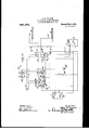
will be set forth in the i `l l Y* 'n gs, Itiguie 1 shows diagrammatically the preferred embodiment of my invention, and Fig. 2 represents an alternative construction. In Fig. 1 I have shown diagrammatically my invention as such as represented in the a construction applied to Bowne Patent 850,018, and from the following description it will be evident to any in the art how n tually adapted to consider that the tion in Fig. 1 indi with the elevator tion and. feature clearly than detai anism.
1 and 2 representa are supposed to i( and 4, such cars 5 and G are vi which are prefera down in suitable iy invention would be acsuch construction, but I diagrammatic representacates to a person familiar signaling art the operas ot my invention more led draw-ings of the mechplurality of cars which be moving f up and shafts past the floors El being provided with the sin. 1 siial signals for each car,
bly carried by the cars,
and may, if desired, be single electric lights, as is common 1n' the arti.
is a pa ssenger button located at similar one attlic fourth floor. word passengerscontroller I 's-controller such asa pushthe third floor, and 8 a By the do not mean to limit myself to the construction shown,
as I consider tha operated by the intending t other devices, which are passenger when mechanic skilled.
lic wishes to take passage in the elevator,`
would be cqiiival ent constructions.
The iiieaiis fordisplayiiig the signa ls prei"` erabl'v comprises mechanism which is ed to be set in one position by ot' a door push-b adapt# the operation iitton and also a commutator which determines the time 'when tli signal sha] has l en operated my invention ill'i drawings such mechanism set by the bitton on the fourth pivoted arms 9 and 10, gether with pivoted dctents 11 and l be given after the push-butterY andin the eiiiboiliiiieiit of .istrated in Fig. 1 of the push-` loor comprises two one for each car, to-
12 and magnets 13 and 14. The normal position of tl the figure at 50 1e arms are as shownin the lower half of 51, that'is, with the detents 11 and 12 underneath the projections 15 and 1G. venergized it will r IVhen, howeveig'one of said magnets is ockjts detent, as indicated,`
les
lift the arm until and allow the arm to drop slightly and rest upon another pivoted detent 17 or 18, as shown. The detents 11 and 12 are obviously prevented from returning to their normal positionas t-he projections 15 and 16 stand in front of them. If the detents 17 and 18 are withdrawn, the arms will drop suflif ciently to cause the fingers 19 and 20 to enter the mercury pots 21 and 22 and close the circuits through t-he signals from the dynamo or other source of E. M. F.- 23. AIn order to operate these detents 17 and 18, a cominutator is provided for commuting o'r successively closing or opening a series of electric circuits, one part of which is moved correspondingly with the car and the other part or portions of which are relatively stationary. In the present embodiment the commutator renders the signals inoperative except when the car is approaching and is adjacent the Hoor on which a passengers controller has been operated and 4comprises suitable fixed contacts, and brushes moved correspondingly wit-h the movement of the elevator, as is common, but preferably much slower. I have not shown the connection bet-ween the moving brushes and the hoisting mechanism of the car, because it would complicate the drawings and it is evident to any mechanic skilled in the art. In the present embodiment the fixed contacts of the commutator for car 2 are indicated by 24 and 26, andthe moving brush as 28. The commutator for car 1 consists of the fixed contacts 31 and 33, and the'moving brush 34. I have also provided in the present instance fixed contacts 25, 27, 30 and 32, and moving brushes 29 and 35, which I have lfor convenience embodied as parts of the commutator, although thisis not necessary in all cases. It will be observed that when brush 28 strikes contact 24, a circuit will be closed from the battery 3G through the magnet'37, which will energize the magnet and draw the detent 17 out from under the projection 38 and allow the arm t) to drop the finger 19 into the mercury pot 21, which will` close the circuit through the lamp 5, thus indicating to the operator of the car that he is expected to stop at the fourth floor. The pin andslot connection indicated at 39 and 4() between the arms 9 and 10 allows either arm to drop into its mercury pot independently ot' the other one.
The restoring mechanism for restoring the arm to normal condition may, if desiredbe a projection 42 on the endo't the arn'rwhich will be engaged by a l'noving.portion 'of the f'xnnmntator, .such as Inni-5h28, `which will both detents 1,1 and 17 drop baci.r because of their over/weighted ends to the normal position under the projections 15 and 58, thus restoring the parts to normal condition. The pin 35) on arm 9 will strike the bottom of the slot4l),.and
similarly raise the arm 10, thus also restoring it to normal condition, although this is not necessary in some cases.
The operation of the commutator of car 1 is substantially the same as just described with reference to the arm 10 and the signal 6 inthe car. The arm 10 will be similarly restored by brush 34 and as the top of slot 40 will strike pin`39, it will, preferably, also res'tore arm In order to allow the operator of car 2 to run past the floor if he desires, and still leave the push-button-operated mechanism which correspondsto the other car, in position'such lvthat t-he signal of t-he other vcar will be displayed when its commutator touches the proper contact, I have provided transfer means which is in part carried by the car and operablevby the operator thereof and which Vis adapted to cause the pushbutton-operated arm 10 of the other following car 1 to be left in the set position after car 2 has restored arm 9 to normal position. This is preferably accomplished by re-setting arm 10 to t-he position shown. This transfer means, in the present embodiment of my,invention,eomprises s transfer button or switch 43 in car 2, a moving brush 29 of the commutator, and the fixed commutator contact 25. The brush 29 strikes the -contact 25 just after'brush 28 has raised arm 9 and passed out of engagement with the same. If, therefore, switch 43, he will close a circuit from battery 36, through such switch, brush 29 and contact 25, and from there through setting magnets 13 and 14 in series, and back to the battery, thus drawing detents 11 and 12 to the position shownand .resetting arm 10 (and preferably arm 9 also) in the set position, which is the same as would result if the push-button 8 were again pushed.. This will obviously leave the parts in c011- dition such that when the connnutator brush 34 of'car 1 strikes contact- 31, the car 1 will receive the signal to stop at the floor'. The brush 34 will then, thecar passes on, strike the end 44 of arm 10, and the transferred signal will be restored to normal condition, or, if desired, the operator of car` 1 may press his transfer button 46 when brush 35 strikes cont-act '30 and pass on, resetting arm t) in the position shown.
The mechanism for operating the signals when the' car is approaching Hoor 3 is substantially the same as abovey described, comprising arms 5Q, 5l, the magnets 52, 53 which are operated by the push-button 7 or transfer button 46 to `withdraw the dei tents 54, 55, the magnets 56 and 57 for Withdrawing the detents 58, 59, and 4the mercry pots and fingers 60, 61 and 62, 63. v
It will be obvious that the signals are displayed by the conjoint operation or action of the push-button-operated mechanism and the operator of the car closes the respective commutatore, in the sense that the push-button must be operated and the moving brush of the comn'nitator must touch its corresponding contact before the signal will be given. In the embodiment ot my invention-shown in the drawings the operation of either one without the other will not display the signal.
In Fig. 2 1 have, for the purposes o1 illustration merely, shown a nloditicatioii of my invention which is adapted to be used with, for example, the construction shown in the Smalley & Reiners patent, heretofore-mentioned. In this construction 7() and 71 are the two cars, 72 and 73 the floor pushbuttons, 74 and 75 the transfer l..u.1ttons,iand 70 to 87 the fixed, and Si) to 911 the moving, parts of the ctm'nnutators. 95 and 0G are .magnets for setting or resetting the pivoted arms 07, S through withdrawal of the weighted dctents 99 and 100, and 10.1 and 102 are the restoriiig magnets, and 103 and 101 the mercn ry pots. 107 and 10S are the signal lamps. In this modification the push-button 72 has been puslaal to energize magnet 00 and rock datent 5)!) to release the mercury pot arm 07 which has dropped into the mercury pot 1011, and the moving brush 90 Aolf the connnutator has touched fixed contact-821, therefore closing the circuit through the ear light 107 which indi fated as lighted. When the moving brush 0l. strikes contact S2 it; will energize mag-net 102 and draw the pivoted arm 07 bach to the position ol. theI .similar arm 0S, detcnt 90 dropping,r back to the position oit detent 100, thus rcstoring the circuits to normal condition. 1t the operator ol car 7() wishes to reset arm 97 in the position shown, he presses the trans- 'ler button 75 as the moving brush 80 strikes contact -l, which will again close the cirrnit through magnet 96 and attract the dctrnt 00, thus allowing arm 07 to be reset in the position shown, so that when car 71 comes along it will receive its signal when the moving brush 03 strikes fixed contact 77.
.Hier a lloor push-buttmi has been pushed and a car operator has pressed his transiter hillton. the signal will stand for the next succeeding car in the sense that the parts are lett in such a position that the next tollowing car will receive its signal at the proper time.
Ut course it will be understood that` in both tigurrs the tixed. and moving portions of the connnntators are sodisposrd that the signal would lbe given somewhat betere the car reaches the loor at which itis to stop, such, .tor cxaniple, .as two tloors in advance ot' the oar. ln Fig. 1 car 2 is moving upwardly and at about the second floor as the moving brush 28 is about to engage the tixcd car light cpntact 24;. In Fig. 2 car 70 at about the third floor. The' moving brushes 28 and 34 ot the cormnutator in Fig.
1 are pivoted so that when moving in the opposite direction they will rock on their pivots when they strike the insulated ends of the arms and pass'hy the same. I have not considered it necessary to show the apparatus -tor use when the car is moving downwardly, as this will be evident to any mechanic skilled in the' artand familiar with the patents heretofore mentioned. I have also shown visual signals for each car in the form of electric lamps stationarily located at the floors, one for each carat each floor, for signaling to the intendingr passenger, Such tloor lamps tor car 2 are shown at 120 and 1,21 in Fig. 1, and for car 1.` at 122 and 123. In Fig. 2 the similar lamps are indicated at 110, 111, 115 and 110. In this latter iigure are shown other stationary contacts 112, 113, 117 and 118, and moving tloor lamp brushes 11-1 and 11.0.
'-11 is ablock on lever 10 which rests on top of the armature 1S. 17 is the magnet which moves said armature.
ttl and 1S) are fixed pivots on which the armsl 9 and 10 rock. (54 and (55 are the similar lixed pivots for the levers 50 and 51.
(Sti is a slot in lever l similar to thel slot -l-O in lever 10.
125 and 120 are insulating portions of the levers i) and which serve to insulate the pins 1f.) and 20 from the rest of the arms.
(57 and (5S are insulated portions at the ends oli the arms and`51.
1,250 is a stop pin, movable with lbrush 2S, to normally hold the moving brush28 from moving bcyon d its position shown under impulso of spring 127. 131 is a similar stop for thc brush 3 4. r
105` and 10G are suitable sources of electron'lotive torce, such as a dynamo and a battery, i'esl'iectively.
I am aware that my invention may be embodied in various other forms without departing from the spirit ot the same as set forth in the claims. fl therefore-do not limit myself to the constructifm shown in the drawings. i
that l claim is:
1. yln an electric signaling apparatus for elevators, the combination ot visual signals for the several elevator cars, individual comnmtators .t'or cimtrolling the pilssage of current through said visual signals, a restoring mechanism whereby said visual signals are brought to inactive condition, resetting mechanism lo'r thereafter resetting the parts in position such that the connnutatorsmay cause the-signals to be displayed, electric rirruits loading from said resetting ,mechanism to the elevator'cars, and a circuit-controlling mechanism within each car whereby the said resetting mechanism can be controlled. to permit the signal to stand for the next succeeding car. i
2. In an electric signaling apparatus .for
elevators, the combination of visual signals for a plurality of elevators, individual com- -tons being connected With the resetting mechanism of said commutators in s uch a manner'that by the actuation of said buttons the operation of the resetting mechanism can be controlled to transfer the signal.
v3. In an electric signaling apparatus for elevators in combination, a pair of cars, an electrically-operated signal for each car, means for operating said signals comprising `a passengers controller located at a floor and mechanism set byl the operation of said passenge1"scontroller, signal transfer means in part carried by each car and operable by the operator of the car for settingsaid passengers-controller-operated mechanism in posltion such that the signal of the other car will be operated, and means for restoring said mechanism to' normal condition whereby the transferred signal is restored to normal condition, said transfer means comprising mechanism rendering said transfer means incapable of controlling 'said passengers-controller-operated mechanism except when the car from which the transfer means has been operated is adjacent the vfloor on which said passengers controller is located.
4. In an electric signaling apparatus for elevators in combination, a palr of cars,' a visual signal carried by each cal-,means for displaying said signals comprising a passengers-,controller locatedA at a floor, a commutator for and operated b each car and mechanism set by the operatlon of said passengers-controller, said commutator and mechanism acting conjointly to determine the time when a signal shall be given, signal transfer means inpart carried by: each car and operable by the operator of the car for setting said passengers-controller-operated mechanism in position such that the signal of the other car will be displayed, and means for restoring said mechanism to normal condit' n whereby the transferred signal is restored to normal condition.
5. In an electric signaling apparatus for elevators, the combination of a pair of -cars,
a visual signal for each car, means for Adisplaying sald slgnals comprlsmg a passengers controller located at a floor and mechanism for each car set by' the operation of` said passengers-controller, signal transfer means in part carried by each car and operable by the operator of each car for setting said passengcs-controller-operated mecha- A fuji nism which corresponds to the other car in position such that the signal ofthe other car Will be displayed, and means y said mechanism to normal condition whereby the transferred signal is restored to normal condition, said transfer means compriswhich said passengers-controller is located.
6. In an electric signaling apparatus for elevators, the combination of a air of cars, an electrically-operated signal or each car,
lmeans for determining the .time when .said
signals may be operated and comprising a passengers-controller located at a floor and a commutator for each car operated correspondingly with the movement of such car for restoring v and mechanism set by the passengers-controller, restoring means operated by each car for restoring to normal condition the mechanism so set by said passengers-controller, and signal transfer means in part carried by each car and operable by the operator of the car for resetting the said passengers-controller-operated mechanism.
7. In an electric signaling apparatus for elevators, the combination of a air of cars and floors, a visual signal carrled by each car, means for determining the time when said signals may be displayed and cornprising a passengers-controller located at each floor, a commutator for each car operated correspondingly with the movement of such `car andV mechanism corresponding to each floor set by said passengers-controller, restoring means operated by each car for restoring to normal condition the mechanism so set by said p assengers-controllers, and signal transfer means inpart carried by each car and operable by the operator of the car for resetting either ofthe said passengers-controller-operated mechanisms.
8. In an electric signaling apparatus for elevators, the combination of a air of cars and floors, a visual signal carrled by each car, means for determining the'time when -said signals may be displayed and comprising a passengers'-controller located at each floor, a commutator for each car operated correspondingly with the movement of such car and mechanism corresponding to each floor set by said passengers-controller, sald mechanism so set being common to both cars,
restoring means operated by each car for restoring to normal condition the mechanism so set by said passengers-control1ers, and signal transfer means 1n part carried Aby each car and operable by the operator of the car for resetting either of the said passengers-controller-operated mechanisms. 9. In an electric slgnalmg apparatus for elevators, the combination of a pair of cars, a visual signal for each car. means for determininnv the time` when said signals may be displayed and comprising a jJassengeWscontroller located at a floor and a commutator for each car operated eorrespol'nlingly with the movement of sneh car and mecha nism tor each car set by the passengers controller, restoring means operated hy each ear for restoringto normat condition the mechanisms so set by said jmssengers-con- 'trollen and signal transfer means in part carried by each car and operable by the operator of'the car for resetting the said passengers-controller-operated mechanism which corresponds to the other car.
l0. In an electric signalii'ig apparatus for elevators, the combination of a pair of ears, an electricaily-operated signal for each car, means for operating,r said signals coi'nprising, and operating by the joint action of, a con'imutator t'or and operated by each car correspondingly to the n'iovement thereof and mechanism to be set, signal transfer means in parti carried by each car and operable by the operator of the car for setting the said'mecl'iaiiism in position such that the signal of said other car will be operated, and restoring means for restoring said mechanism to normal condition.
11. In an electric sigmaling4 apparatus for elevators, the combination of a pair of cars, a visual signal carried by each ear, means for displaying said signals comprisinf, and operating by the joint action of, 'i commutator for and operated by each car corresl'ionclingly to the movement thereof and mechanism to be set, signal transfer means in part carried by each car and operable Ly the ojierator of the. ear for setting the said n'ieehanisni in position such that the signal ot. said other car will be displayed, and restoring means for restoringsaid meeh-y anism to normal condition.
l2. In an electric signaling apparatus for elevators, the combination of a pair ot cars, an electricallyo]ierated signal tor each car,
means for ol'ieratii'ig said signals comprisf ing,- and operated by the joint action of, a eomn'mtator -tor and operated by each car correspondingly to the movement. thereof and nler-lmnisni for each ear adapted to be set; signal transfer means in part carried by each car andoperable by the operator ot" the ear For .sw-Ning` the said lneehanir-an which eori'esl'ionils t o the other rar irt'position surh that. the signal otl said` other ear will be operated, and restoringt means for restoring' said mechanism to normal condition.
lf3. ln an electric signaling apparatus for elevators, the combination ol' a pair olf ears, a visual signal tor Veach earA` means -t'nr'de'f termining' the tim(l when a signal can be displayed and comprising a :lssc|1g( n"s co1,-troll er located at a tloor said ar and operable by the operator of said car and adapted to cause the passengers-controller-ojierated mechanism ot the other following car to he left in the set position after the restoring means of the first ear has operated, said t an-ster means comprising mechanism rendering?r said transfer 1n x,ans incapable of controlling said passenger`scontroller-operated mechanism except when the car :from which the 'transfer means has been operated is adjacent the tloor on which said passengeris-controller is located.
llt. In an electric Signaling apparatus for elevators, the combination of a pair of cars, a visual signal for each car, means for determining the time when a signal can be displayed and comprising a commutator opera ted by each car and a passenge'fscontrolter located at a floor and mechanism for each car adapted to be set; by said passenger-scontroller, restoring means operated by one car and adapted to restore at least its own passengers-controller-operated mechanism to normal condition, and signal transfer means in part carried said car and operable by the'operator of said car and adapted to canse the passe1ige1"s-controller-operated mechanism of the other ",folloiying car to be. left in the set position latter lthe restoring means of the first car hasl operated, and restoringr means for restoringr to normal condition the passengers-controller-set mechanism of said following car.
15. In an elevator signaling apparatus in combination, a car, a signal for the same, means for operating' said signal comprising a passengeI"s-eonti'oller located ata floor and mechanism set when said coi'ltroller is o perated, a second ear and a signal tor the same, signal transfer means in part, 'arried by said second car and ctmtrolled by the n'lovementI of said ear and ander control ot the operator thereof and adapted, when operated, to canse the passengers-controlleroperated mechanism which controls the sig nal of the tirst. ca r to be setJ in its operative position,` and restoring' means operated by said first mentioned car 't'or thereafter restoring said passenger-sawuitroller-operated mechanism to normal condition.
lt. ln an elevator signalingr apparat ns in combination, a car, a signal for the Same, means for oj'ieratine said signal comprising a |)assengers-controller located at a Hoor and meclninisn'i set. when said controller is operated, a second car and a. signal for the same` signal. transfer means in part carri rl and mechanism by `said second car and under control of the operator thereof and adapted, when operated, to cause the passengers-controller-op erated mechanism which controls the signal of the first car to be set in its operative po` sition, and restoring means operated by said Iirst mentioned car for thereafter restoring said passengers-controller-operated 'mechanism to normal condition, said transfer means also comprising mechanism Which is operated by said second car and which ren- -ders said transfer means inoperative except when said second car is adjacent the floor on which said passengers-controller is located.
17. In an elevator signaling apparatus in combination, a car, a signal :for the same, means for operating said signal and comprising a passengers-controller located at a fioor, a magnet controlled thereby, and mechanism controlled by said magnet and set when said magnet is energized, a second car and a signal' for the same, signal transfer means in part carriedby said second car and under control of the operator'thereof and adapted, when operated,to energize said magnet and thereby cause the passengerscontroller-operated mechanism which controls the signal of the first car to be set in its operative position, and restoring means operated by said first mentioned car for thereafter restoring said passengers-controlleroperated mechanism to normal condition,
said transfer means comprising mechanism' rendering said transfer means incapable of controlling said passengers-controller-operated mechanism except when the car from which the transfer means has been operated g is adjacent the floor on which said passengers-controller is located. i
18. In an elevator signaling apparatus in combination, a car, electrically-operated means for signaling the operator carried thereby, means for displaying a signal comprising a passengerscontrozller located at the operator thereof and adapted, when op s by said first car for restoring to normal condition the mechanism so set by said transfer means.
19. In a signaling apparatus for elevators in combination, a pair of cars and a plurality of floors assed by said cars, .electricallyoperated signal means carried byl each car and adapted to signal the operator to stop atthe floors, means for operating said signals comprising a passengers-controller at each floor and mechanism corresponding to each floor set by operation of its corresponding passengeris-controller, signal-transfer mechanism comprising a switch in each car operable by the operator of the car for setler-operated mechanisms corresponding to the other car in position such that the signal means of the other car Will be operated, and
means for restoring said mechanisms to 'norl mal condition.`
Signed at New of February 1908.
JAMES M. GRAHAM.
York, N Y. this 21st day lVitnesses EMERSON R. NEWELL, BEATRICE Mrnvls.
Priority Applications (1)
| Application Number | Priority Date | Filing Date | Title |
|---|---|---|---|
| US41763608A US991973A (en) | 1908-02-25 | 1908-02-25 | Elevator signaling apparatus. |
Applications Claiming Priority (1)
| Application Number | Priority Date | Filing Date | Title |
|---|---|---|---|
| US41763608A US991973A (en) | 1908-02-25 | 1908-02-25 | Elevator signaling apparatus. |
Publications (1)
| Publication Number | Publication Date |
|---|---|
| US991973A true US991973A (en) | 1911-05-09 |
Family
ID=3060308
Family Applications (1)
| Application Number | Title | Priority Date | Filing Date |
|---|---|---|---|
| US41763608A Expired - Lifetime US991973A (en) | 1908-02-25 | 1908-02-25 | Elevator signaling apparatus. |
Country Status (1)
| Country | Link |
|---|---|
| US (1) | US991973A (en) |
-
1908
- 1908-02-25 US US41763608A patent/US991973A/en not_active Expired - Lifetime
Similar Documents
| Publication | Publication Date | Title |
|---|---|---|
| US991973A (en) | Elevator signaling apparatus. | |
| US1905228A (en) | Signaling system for elevators | |
| US1370111A (en) | Elevator system | |
| US2093074A (en) | Electrical control device | |
| US748409A (en) | Elevator signaling apparatus. | |
| US1173192A (en) | Elevator signaling apparatus. | |
| US677891A (en) | Controlling apparatus for elevators. | |
| US2338582A (en) | Elevator signaling system | |
| US666699A (en) | Electric elevator. | |
| US462834A (en) | armstrong | |
| US1608094A (en) | Automatic schedule regulator for dispatching systems | |
| US1132607A (en) | Elevator signaling system. | |
| US748408A (en) | Elevator signaling apparatus. | |
| US1195600A (en) | Mette | |
| US733750A (en) | Signaling apparatus for elevator-cars. | |
| US634226A (en) | Electric switch or signal apparatus. | |
| US700619A (en) | Elevator signal device. | |
| US1112379A (en) | Elevator signal system or apparatus. | |
| US786016A (en) | Combined electric and mechanical signal apparatus for elevators. | |
| US711202A (en) | Electric signaling system. | |
| US1276158A (en) | Elevator-signal. | |
| US1844546A (en) | Signal system for elevators and other conveyers | |
| US1699876A (en) | Elevator signaling system | |
| US572562A (en) | Elevator signal mechanism | |
| USRE12313E (en) | Reissued feb |