US9917902B2 - System and method for scalable and efficient deployment of wireless infrastructure nodes for multiple collocated wireless field device networks - Google Patents
System and method for scalable and efficient deployment of wireless infrastructure nodes for multiple collocated wireless field device networks Download PDFInfo
- Publication number
- US9917902B2 US9917902B2 US14/848,956 US201514848956A US9917902B2 US 9917902 B2 US9917902 B2 US 9917902B2 US 201514848956 A US201514848956 A US 201514848956A US 9917902 B2 US9917902 B2 US 9917902B2
- Authority
- US
- United States
- Prior art keywords
- field device
- wfn
- data packet
- wireless infrastructure
- network
- Prior art date
- Legal status (The legal status is an assumption and is not a legal conclusion. Google has not performed a legal analysis and makes no representation as to the accuracy of the status listed.)
- Active, expires
Links
Images


Classifications
-
- H—ELECTRICITY
- H04—ELECTRIC COMMUNICATION TECHNIQUE
- H04L—TRANSMISSION OF DIGITAL INFORMATION, e.g. TELEGRAPHIC COMMUNICATION
- H04L67/00—Network arrangements or protocols for supporting network services or applications
- H04L67/01—Protocols
- H04L67/12—Protocols specially adapted for proprietary or special-purpose networking environments, e.g. medical networks, sensor networks, networks in vehicles or remote metering networks
- H04L67/125—Protocols specially adapted for proprietary or special-purpose networking environments, e.g. medical networks, sensor networks, networks in vehicles or remote metering networks involving control of end-device applications over a network
-
- H—ELECTRICITY
- H04—ELECTRIC COMMUNICATION TECHNIQUE
- H04L—TRANSMISSION OF DIGITAL INFORMATION, e.g. TELEGRAPHIC COMMUNICATION
- H04L45/00—Routing or path finding of packets in data switching networks
- H04L45/74—Address processing for routing
-
- H—ELECTRICITY
- H04—ELECTRIC COMMUNICATION TECHNIQUE
- H04L—TRANSMISSION OF DIGITAL INFORMATION, e.g. TELEGRAPHIC COMMUNICATION
- H04L47/00—Traffic control in data switching networks
- H04L47/70—Admission control; Resource allocation
- H04L47/80—Actions related to the user profile or the type of traffic
- H04L47/805—QOS or priority aware
-
- H—ELECTRICITY
- H04—ELECTRIC COMMUNICATION TECHNIQUE
- H04W—WIRELESS COMMUNICATION NETWORKS
- H04W4/00—Services specially adapted for wireless communication networks; Facilities therefor
- H04W4/30—Services specially adapted for particular environments, situations or purposes
- H04W4/38—Services specially adapted for particular environments, situations or purposes for collecting sensor information
-
- H—ELECTRICITY
- H04—ELECTRIC COMMUNICATION TECHNIQUE
- H04W—WIRELESS COMMUNICATION NETWORKS
- H04W56/00—Synchronisation arrangements
- H04W56/001—Synchronization between nodes
-
- H—ELECTRICITY
- H04—ELECTRIC COMMUNICATION TECHNIQUE
- H04W—WIRELESS COMMUNICATION NETWORKS
- H04W84/00—Network topologies
- H04W84/18—Self-organising networks, e.g. ad-hoc networks or sensor networks
Definitions
- This disclosure relates generally to industrial process control and automation systems. More specifically, this disclosure relates to a system and method for scalable and efficient deployment of wireless infrastructure nodes for multiple collocated wireless field device networks.
- control systems are often used to automate large and complex industrial processes. These types of systems routinely include sensors, actuators, and controllers. Some types of controllers typically receive measurements from the sensors and generate control signals for the actuators.
- field devices Some field instruments and field devices (collectively referred to as “field devices”) include sensor nodes used to obtain measurements of particular characteristics in an industrial process. Other field devices include actuator nodes used to adjust operations in the industrial process. A field device exchanges information with the control system over a wired or wireless interface.
- a wireless field device includes transceiver circuitry that is capable of wirelessly transmitting and receiving information.
- Some wireless networks can include a large number of wireless field devices.
- a wireless network may be used to transport sensor information from numerous wireless field devices to a controller of the control system.
- This disclosure provides a system and method for scalable and efficient deployment of wireless infrastructure nodes for multiple collocated wireless field device networks.
- a wireless infrastructure node includes at least one processing device configured to receive a data packet from a wireless field device network (WFN) controller, where the data packet includes a network identifier.
- the at least one processing device is also configured to determine a field device network to receive the data packet based on the network identifier.
- the at least one processing to device is further configured to transmit the data packet to a field device in the field device network.
- the wireless infrastructure node, the WFN controller, and the field device network comprise one logical WFN among a plurality of logical WFNs.
- the wireless infrastructure node is one of a plurality of pooled infrastructure nodes configured to communicate between a plurality of WFN controllers and a plurality of field device networks arranged in the plurality of logical WFNs.
- a method in a second embodiment, includes receiving, at a wireless infrastructure node, a data packet from a WFN controller, where the data packet includes a network identifier. The method also includes determining, at the wireless infrastructure node, a field device network to receive the data packet based on the network identifier. The method further includes transmitting, by the wireless infrastructure node, the data packet to a field device in the field device network.
- the wireless infrastructure node, the WFN controller, and the field device network comprise one logical WFN among a plurality of logical WFNs.
- the wireless infrastructure node is one of a plurality of pooled infrastructure nodes configured to communicate between a plurality of WFN controllers and a plurality of field device networks arranged in the plurality of logical WFNs.
- a system in a third embodiment, includes a plurality of WFN controllers and a plurality of field device networks, where each field device network includes one or more field devices.
- the system also includes a plurality of wireless infrastructure nodes arranged in a shared pool.
- the pooled infrastructure nodes are configured to communicate between the plurality of WFN controllers and the plurality of field device networks.
- Each wireless infrastructure node is configured to receive a data packet from a first one of the WFN controllers, where the data packet includes a network identifier.
- Each wireless infrastructure node is also configured to determine a first one of the field device networks to receive the data packet based on the network identifier and transmit the data packet to a field device in the first field device network.
- the WFN controllers, the field device networks, and the wireless infrastructure nodes are arranged in a plurality of logical WFNs, where each logical WFN includes a WFN controller, a field device network, and the pooled infrastructure nodes.
- FIG. 1 illustrates an example industrial process control and automation system according to this disclosure
- FIG. 2 illustrates an example system having a deployment of wireless field device networks (WFNs) according to this disclosure
- FIG. 3 illustrates an example use case highlighting some of the challenges of the system of FIG. 2 according to this disclosure
- FIG. 4 illustrates another example use case highlighting some challenges of the system of FIG. 2 according to this disclosure
- FIG. 5 illustrates an example system having a scalable deployment of logical WFNs according to this disclosure
- FIG. 6 illustrates an example wireless device in an industrial control and automation system according to this disclosure.
- FIG. 7 illustrates an example method for communicating using a scalable deployment of logical WFNs according to this disclosure.
- FIGS. 1 through 7 discussed below, and the various embodiments used to describe the principles of the present invention in this patent document are by way of illustration only and should not be construed in any way to limit the scope of the invention. Those skilled in the art will understand that the principles of the invention may be implemented in any type of suitably arranged device or system.
- FIG. 1 illustrates an example industrial control and automation system 100 according to this disclosure.
- the system 100 includes one or more process elements 102 .
- the process elements 102 represent components in a process or production system that may perform any of a wide variety of functions.
- the process elements 102 could represent sensors, actuators, or any other or additional industrial equipment in a processing environment.
- Each of the process elements 102 includes any suitable structure for performing one or more functions in a processing or production system.
- the phrase “industrial control and automation system” generally refers to a system that automates and controls at least one process.
- a controller 104 is coupled to the process elements 102 .
- the controller 104 controls the operation of one or more of the process elements 102 .
- the controller 104 could receive information associated with the system 100 , such as by receiving sensor measurements from some of the process elements 102 .
- the controller 104 could use this information to provide control signals to others of the process elements 102 , thereby adjusting the operation of those process elements 102 .
- the controller 104 includes any suitable structure for controlling one or more process elements 102 .
- the controller 104 could, for example, represent a computing device executing an embedded LINUX or other operating system.
- a network 106 facilitates communication between various components in the system 100 .
- the network 106 may communicate Internet Protocol (IP) packets, frame relay frames, Asynchronous Transfer Mode (ATM) cells, or other suitable information between network addresses.
- IP Internet Protocol
- ATM Asynchronous Transfer Mode
- the network 106 may include one or more local area networks (LANs), metropolitan area networks (MANs), wide area networks (WANs), all or a portion of a global network such as the Internet, or any other communication system or systems at one or more locations.
- the network 106 could include a FAULT TOLERANT ETHERNET network from HONEYWELL INTERNATIONAL INC.
- the system 100 also includes one or more industrial wireless networks for communicating with wireless sensors, actuators, or other wireless field devices.
- an industrial wireless network includes network routers 108 a - 108 c and infrastructure nodes 110 a - 110 b .
- the network routers 108 a - 108 c and infrastructure nodes 110 a - 110 b wirelessly communicate with each other to form a wireless network, such as a mesh network.
- the network routers 108 a - 108 c could receive data transmitted wirelessly from field devices 112 a - 112 e and route the data to the infrastructure nodes 110 a - 110 b .
- the infrastructure nodes 110 a - 110 b could receive data from the network routers 108 a - 108 c directly or indirectly (such as through other to field routers) and directly or indirectly from the field devices 112 a - 112 e for transmission over a backbone network 114 .
- the network routers 108 a - 108 c and infrastructure nodes 110 a - 110 b could also route data received over the backbone network 114 to the field devices 112 a - 112 e .
- the network routers 108 a - 108 c and infrastructure nodes 110 a - 110 b form a wireless network that can provide wireless coverage to field devices and other devices in a specified area, such as a large industrial complex.
- the wireless network can support any suitable industrial wireless network protocol(s), such as ISA100.11a Wireless or WirelessHART.
- the network routers 108 a - 108 c and infrastructure nodes 110 a - 110 b generally represent routing devices that store and forward messages for other devices.
- the network routers 108 a - 108 c may be locally or battery powered.
- Infrastructure nodes 110 a - 110 b may be line-powered, meaning these devices receive operating power from external sources (such as A/C supply lines).
- the network routers 108 a - 108 c may be line-powered, or the infrastructure nodes 110 a - 110 b may be locally powered such as by batteries (referred to as locally-powered).
- the field devices 112 a - 112 e generally represent non-routing devices that are routinely locally-powered, although a field device could provide routing functionality or be line-powered.
- Each network router 108 a - 108 c and infrastructure node 110 a - 110 b includes any suitable structure facilitating wireless communications, such as a radio frequency (RF) spread-spectrum or orthogonal frequency division multiplexing (OFDM) transceiver.
- Each of the infrastructure nodes 110 a - 110 b also includes any suitable structure facilitating communication over the backbone network 114 , such as an Ethernet transceiver.
- the network routers 108 a - 108 c could represent field device access points (FDAPs) that are not connected via wired Ethernet and may be locally powered, and the infrastructure nodes 110 a - 110 b could represent FDAPs that are connected via wired Ethernet and may be line powered.
- the backbone network 114 includes any suitable network for transporting data, such as a FAULT TOLERANT ETHERNET network, a wireless mesh network, or other wired or wireless network.
- a gateway 116 couples the network 106 and the backbone network 114 .
- the gateway 116 can perform security functions to allow only authorized traffic to flow between the networks 106 and 114 .
- the gateway 116 can also perform translation functions to translate between protocols.
- the gateway 116 includes any suitable structure for providing access to networks and translating between protocols used by those networks.
- the gateway may be part of a network controller 120 , or the network controller 120 and the gateway 116 may represent separate components.
- An application/protocol server 118 can configure and control various aspects of the system 100 via the network controller 120 .
- the server 118 can allow for the control of process elements 102 via the controller 104 and via the network controller 120 , which configures the operation of the network routers 108 a - 108 c , infrastructure nodes 110 a - 110 b , and field devices 112 a - 112 e .
- Another function of the network controller 120 can be to control and manage the networks 106 , 114 by determining which and how wireless devices should connect to one another to form a resilient mesh or star network.
- the server 118 could also support security in the system 100 , such as by allowing the network controller 120 to distribute cryptographic keys or other security data to various wireless devices or other components.
- the server 118 includes any suitable structure for operating industrial control and automation system 100 .
- various devices in the wireless network of FIG. 1 form a mesh network communicating at 2.4 GHz or 5.8 GHz.
- data can be injected into the wireless mesh network through the routers or field devices, thus providing versatile, multifunctional, plant-wide coverage for wireless sensing, asset location tracking, personnel tracking, wireless communications, and any other or additional functionality as desired.
- one or more components in the system 100 support the use of a pool of shared wireless infrastructure nodes that are capable of communicating data packets for multiple logical wireless field device networks. This functionality is described in greater detail below.
- FIG. 1 illustrates one example of an industrial control and automation system 100
- the system 100 could include any number of each component.
- the functional division shown in FIG. 1 is for illustration only.
- Various components in FIG. 1 could be combined, subdivided, or omitted and additional components could be added according to particular needs.
- the industrial control and automation system 100 could support any number of wireless networks with or without any wired networks.
- FIG. 2 illustrates an example system 200 having a deployment of wireless field device networks (WFNs) according to this disclosure.
- WFNs wireless field device networks
- One or more of the components of the system 200 may represent (or be represented by) one or more of the components of the industrial control and automation system 100 shown in FIG. 1 .
- the phrase “wireless field device network” encompasses a variety of wireless networks in industrial applications that include various types of field devices.
- a wireless field device network is a wireless sensor network.
- a typical wireless field device network deployment such as in the system 200 , involves upfront engineering effort and one or more site surveys with the goal of providing maximum coverage to a particular geographic area. This coverage is often provided with a single wireless mesh network using multiple infrastructure nodes such as FDAPs.
- the system 200 includes a plurality of WFNs 201 a - 201 n deployed in a geographical area, such as an industrial plant.
- Each WFN 201 a - 201 n includes one or more wireless infrastructure nodes 202 , a WFN controller 203 a - 203 n , and one or more field devices 204 .
- Each WFN 201 a - 201 n is under the control of the respective WFN controller 203 a - 203 n .
- the one or more wireless infrastructure nodes 202 are arranged in infrastructure node mesh networks 210 a - 210 n (or “INODE networks” for short). In some embodiments, one or more of the infrastructure nodes 202 may represent FDAPs.
- each INODE network 210 a - 210 n and a WFN controller 203 a - 203 n is in communication with one or more field devices 204 , which may be arranged in a field device network 220 a - 220 n .
- each INODE network 210 a - 210 n and its associated field devices 204 are associated with a particular smaller geographical footprint within the larger geographical area, such that there may not be much (if any) geographical overlap between adjacent WFNs 201 a - 201 n.
- Each wireless infrastructure node 202 may be associated with one and only one WFN or subnet. Each wireless infrastructure node 202 has the capacity to support communications with a number of field devices 204 , such as N devices. Thus, if there are M wireless infrastructure nodes 202 in an INODE network 210 a - 210 n , the overall capacity of the INODE network 210 a - 210 n can be M ⁇ N field devices. In addition, each WFN controller 203 a - 203 n can have the capacity to control J ⁇ M ⁇ N field devices 204 .
- each WFN 201 a - 201 n is therefore typically limited by the WFN controller 203 a - 203 n , which has a lower capacity than the INODE network 210 a - 210 n .
- any excess capacity of the WFN (such as M ⁇ N ⁇ J devices) may go to waste.
- New infrastructure (such as additional WFNs and WFN controllers) may need to be deployed to increase overall system capacity, even if the additional field devices are within radio reach of existing wireless infrastructure with excess backbone capacity. This has a number of disadvantages—there is a financial cost to added deployment, and the radio spectrum becomes more crowded and may degrade overall system performance with additional deployment.
- FIG. 3 illustrates an example use case highlighting some of the challenges of the system 200 of FIG. 2 according to this disclosure.
- the system 200 is deployed with a plurality of wireless infrastructure nodes 202 in multiple NODE networks 210 a - 210 n for plant-wide coverage.
- the quantity and coverage of the wireless infrastructure nodes 202 in the system 200 is typically determined by taking into account any future needs for additional field devices 204 .
- Each WFN 201 a - 201 n can often only support a fixed number of field devices 204 using its associated WFN controller 203 a - 203 n and INODE network 210 a - 210 n of wireless infrastructure nodes 202 .
- the capacity limitations are driven by (i) the capacity of each WFN controller 203 a - 203 n and (ii) the overall capacity of the set of wireless infrastructure nodes 202 in the INODE network 210 a - 210 n . These two capacity limits are largely independent of each other. This means it is possible to reach the capacity of a WFN controller 203 a - 203 n without exhausting the collective capacity of the wireless infrastructure nodes 202 .
- a plurality of field devices 204 are coupled to the WFN controller 203 a through the wireless infrastructure nodes 202 of the INODE network 210 a .
- additional field devices 204 may be deployed in the system 200 as needed until the capacity limit of the WFN controller 203 a is met.
- adding another wireless field device 205 may require deployment of a new INODE network of wireless infrastructure nodes 202 or an additional WFN controller 203 b within the same geographical area.
- This new infrastructure adds engineering, deployment, and maintenance costs as well as possible radio interference to the previously deployed infrastructure units.
- a plant operator would like the ability to add a new field device 205 anywhere within the plant coverage area of the wireless infrastructure nodes 202 and control the new field device 205 with the WFN controller 203 b .
- the WFN controller 203 b provides increased capacity, the plant operator may not be able to simply add the new field device 205 without additional costs of survey, engineering, and installation of a new INODE network. This is indicated in FIG. 3 by the circle with the diagonal line through it.
- some existing wireless infrastructure nodes 202 may have to be redeployed or reprogrammed to join the new WFN controller 203 b in order to provide a path back to the WFN controller 203 b .
- This can create coverage holes for existing field devices 204 that had relied on the now-redeployed wireless infrastructure nodes 202 for good connectivity.
- another set of wireless infrastructure nodes 202 may be needed to provide end-to-end connectivity to the WFN controller 203 b . This scenario effectively limits overall system capacity and results in unused or wasted excess capacity.
- FIG. 4 illustrates another example use case highlighting some challenges of the system 200 of FIG. 2 according to this disclosure.
- One challenge is that for any given WFN there is no mechanism for logically separating and grouping of wireless instruments to meet application needs.
- the system 200 allows the use of multiple logical subnets, each subnet may require its own set of infrastructure nodes, which does not address the problem of underutilized infrastructure or deploying unnecessary collocated infrastructure nodes.
- each field device network 220 a - 220 b includes one or more field devices 204 .
- the separate field device networks 220 a - 220 b are subnets that can be used by different applications or processing units in order to associate the WFN controllers 203 a - 203 b with different field device communities, to limit the scope of loss in the event of a failure, and to allow selective shutdown of field devices 204 for maintenance and turnarounds.
- the wireless infrastructure nodes 202 may have been deployed to achieve a substantially unified backhaul and WiFi access across a plant site. Accordingly, the field device networks 220 a - 220 b may not have caused one or more of the installed wireless infrastructure nodes 202 to reach capacity. That is, one or more wireless infrastructure nodes 202 may have excess capacity that is currently unused.
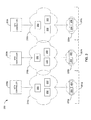
- FIG. 5 illustrates an example system 500 having a scalable deployment of logical WFNs according to this disclosure.
- One or more of the components of the system 500 may represent (or be represented by) one or more of the components of the industrial control and automation system 100 shown in FIG. 1 .
- the system 500 solves the problem of deploying multiple collocated WFNs by enabling a group of wireless infrastructure nodes to support multiple logical WFNs.
- the system 500 includes a plurality of wireless infrastructure nodes 502 , a plurality of WFN controllers 503 a - 503 n , and a plurality of field devices 504 .
- the plurality of wireless infrastructure nodes 502 are arranged in a single INODE network 510 .
- the INODE network 510 represents a pool of shared infrastructure nodes 502 that can be distributed over a large geographical area, such as a physical plant.
- Each WFN controller 503 a - 503 n may be a single physical entity, a single physical entity with multiple subnetworks, or one or more virtualized entities.
- the field devices 504 are grouped into a plurality of field device networks 520 a - 520 n .
- One or more of the field devices 504 may include a wireless sensor for sensing one or more environmental parameters (such as temperature, pressure, vibration, and the like) or a wireless actuator.
- multiple logical WFNs 501 a - 501 n are defined.
- Each of the logical WFNs 501 a - 501 n is associated with a WFN controller 503 a - 503 n and a field device network 520 a - 520 n .
- All of the logical WFNs 501 a - 501 n share the pooled infrastructure nodes 502 in the INODE network 510 .
- the INODE network 510 is common to all of the logical WFNs 501 a - 501 n . This is in contrast to the system 200 , where each WFN 201 a - 201 n has its own INODE network 210 a - 210 n.
- each wireless infrastructure node 502 is configured to communicate with any WFN controller 503 a - 503 n or field device network 520 a - 520 n in its coverage area. That is, the wireless infrastructure nodes 502 do not associate indefinitely with any particular WFN controller 503 a - 503 n or field device network 520 a - 520 n . Thus, the wireless infrastructure nodes 502 can route upstream and downstream communication between different pairs of WFN controller 503 a - 503 n and field device network 520 a - 520 n.
- Each logical WFN 501 a - 501 n is associated with an identifier, such as a wireless field network identifier (WFNID).
- WFNID wireless field network identifier
- each field device 504 can be uniquely identified by a field device name or identifier, sometimes referred to as a device tag.
- the WFNID and device tag values can be assigned by a user (such as a system engineer) or automatically generated and assigned by the system 500 .
- a supervisory WFN controller or other network controller can be employed to manage the multiple logical WFNs 501 a - 501 n or assign identifiers.
- the wireless infrastructure nodes 502 transparently route data packets from a field device network 520 a - 520 n to the intended WFN controller 503 a - 503 n , and vice versa, based on one or more packet identifiers associated with each data packet.
- the packet identifiers may include or identify information such as source, destination, address, network identification, WFNID, and the like.
- Each wireless infrastructure node 502 in the NODE network 510 may possess one or more security keys for each logical WFN 201 a - 201 n or a master key that is associated with multiple logical WFNs 201 a - 201 n .
- Other suitable network identity or security schemes can be used to provide adequate security.
- Time synchronization among the components of the system 500 allows a time synchronization scheme, such as time division multiple access (TDMA), to be used across the multiple logical WFNs 501 a - 501 n .
- TDMA time division multiple access
- Such a time synchronization scheme helps to ensure that all data communication through the NODE network 510 is routed efficiently and accurately with minimal delay or lost packets.
- certain field devices 504 may provide or receive higher priority data or information than other field devices 504 .
- data flow within the NODE network 510 can be prioritized based on data origin, destination, or type of information to ensure quality of service.
- the system 500 includes a number of advantages over other systems.
- the wireless infrastructure nodes 502 can route data packets between any WFN controller 503 a - 503 n and any field device networks 520 a - 520 n , assuming the packet route is within the coverage area of the wireless infrastructure nodes 502 . This represents an improvement over other systems in which the wireless infrastructure nodes 502 are associated with only one WFN.
- the pool of wireless infrastructure nodes 502 in the NODE network 510 is geographically dispersed and shared among the logical WFNs 501 a - 501 n , there is no geographical limitation on the field devices 504 or the field device networks 520 a - 520 n (other than the overall coverage area of the NODE network 510 ).
- the field device networks 520 a - 520 n can represent a logical grouping of devices, rather than a geographical grouping.
- the actual device locations of the field devices in a logical WFN 501 a - 501 n can be anywhere within the coverage area of the MODE network 510 (such as anywhere within an industrial plant).
- the pool of wireless infrastructure nodes 502 in the NODE network 510 is shared, there is no per-WFN capacity limitation due to the capacity of the wireless infrastructure nodes 502 . That is, the overall capacity of all of the to wireless infrastructure nodes 502 (not just a portion of the wireless infrastructure nodes 502 ) in the NODE network 510 can be utilized before there is a need to increase capacity. When capacity is reached, the overall capacity can be increased by adding one or more wireless infrastructure nodes 502 to the NODE network 510 . Each newly added wireless infrastructure node 502 will be able to communicate data packets in any of the logical WFNs 501 a - 501 n , as long as the communication route is within the coverage area of the newly added wireless infrastructure node 502 . This flexible method for utilizing and increasing system capacity results in better overall utilization, reduced engineering costs, and reduced deployment and maintenance costs.
- the grouping and sharing of the wireless infrastructure nodes 502 in the NODE network 510 provide flexibility to add new devices without concern for reaching a system-imposed limit on the number of supported devices, such as may be experienced using smaller, unshared NODE networks. This is new for industrial wireless field device network applications.
- FIG. 5 illustrates one example of a system 500 for scalable deployment of WFNs
- various changes may be made to FIG. 5 .
- the number and types of components shown in FIG. 5 could be greater or fewer depending on implementation.
- various components in FIG. 5 could be combined, subdivided, or omitted and additional components could be added according to particular needs.
- FIG. 6 illustrates an example wireless device 600 in an industrial control and automation system according to this disclosure.
- the wireless device 600 could, for example, represent one of the components shown in FIG. 1 or FIG. 5 .
- the device 600 includes a controller 602 , which controls the overall operation of the device 600 .
- the controller 602 may receive or generate data to be transmitted, and the controller 602 could provide the data to other component(s) in the device 600 for transmission over a wired or wireless network.
- the controller 602 could also receive data over a wired or wireless network and use or forward the data.
- the controller 602 in a router could receive data transmitted wirelessly, determine a next hop for the data (if any), and provide the data for transmission to the next hop (if any).
- the controller 602 in an infrastructure node could perform operations to convert data from one format to another.
- the controller 602 includes any suitable structure for controlling operation of a device.
- the controller 602 could represent a processor, microprocessor, microcontroller, field programmable gate array, digital signal processor, or other processing or control device.
- a memory 604 is coupled to the controller 602 .
- the memory 604 stores any of a wide variety of information used, collected, or generated by the device 600 .
- the memory 604 could store information received over a network that is to be transmitted over the same or other network.
- the memory 604 includes any suitable volatile and/or non-volatile storage and retrieval device(s).
- the device 600 can include additional components depending on the type and operation of the device 600 .
- the device 600 could include at least one wireless transceiver 606 and at least one antenna 608 .
- the transceiver(s) 606 and antenna(s) 608 can be used to communicate wirelessly with one or more sensor nodes, actuator nodes, or other routers.
- a transceiver 606 could have its own antenna(s) 608 , or a collection of transceivers 606 could share one or more antennas 608 .
- Each transceiver 606 includes any suitable structure for providing signals for wireless transmission and/or for obtaining signals received wirelessly.
- Each antenna 608 represents any suitable structure for transmitting and/or receiving wireless signals.
- each transceiver 606 represents an RF transceiver
- each antenna 608 represents an RF antenna. Note that any other suitable wireless signals could be used to communicate and that each transceiver could include a transmitter and a separate receiver. If multiple antennas 608 are used, spatial diversity or other types of diversity can be used to improve communication reliability.
- the device 600 can further include one or more backbone network interfaces 610 .
- the backbone network interfaces 610 allow the device 600 to communicate over one or more backbone networks 114 or other networks.
- Each backbone network interface 610 includes any suitable structure for transmitting and/or receiving signals over a backbone network, such as an Ethernet interface or a wireless transceiver.
- FIG. 6 illustrates one example of a wireless device 600 in an industrial control and automation system
- various changes may be made to FIG. 6 .
- various components in FIG. 6 could be combined, subdivided, or omitted and additional components could be added according to particular needs.
- a “wireless device” or “wireless router” represents any device or router that can transmit and/or receive data wirelessly, even if the device or router has the ability to transmit and/or receive data over a wired connection as well.
- FIG. 7 illustrates an example method 700 for communicating using a scalable deployment of logical WFNs according to this disclosure.
- the method 700 is described as being performed by the system 500 of FIG. 5 .
- the method 700 could be used with any suitable device or system.
- multiple wireless infrastructure nodes are arranged and configured in a pool to be shared among a plurality of logical WFNs.
- the logical WFNs include the shared pool of wireless infrastructure nodes, WFN controllers, and field device networks, where each field device network has one or more field devices. This may include, for example, configuring a system like the system 500 in FIG. 5 .
- a wireless infrastructure node receives a data packet from a WFN controller. This may include, for example, one of the wireless infrastructure nodes 502 receiving a data packet from the WFN controller 503 a .
- the data packet includes a network identifier, such as a WFNID.
- the data packet may also include a device identifier, such as a device tag.
- the wireless infrastructure node uses the network identifier to determine a field device network to receive the data packet. This may include, for example, the wireless infrastructure node 502 determining that the data packet is intended for the field device network 520 a based on the WFNID. In some embodiments, the wireless infrastructure node 502 also uses the device tag to determine a particular field device 504 among the field devices in the field device network 520 a.
- the wireless infrastructure node transmits the data packet to the field device in the field device network. This may include, for example, the wireless infrastructure node 502 transmitting the data packet to a particular field device 504 in the field device network 520 a . In some embodiments, the wireless infrastructure node receives and transmits the data packet according to a time synchronization scheme (such as TDMA) that is commonly used by the pooled infrastructure nodes.
- TDMA time synchronization scheme
- the wireless infrastructure node receives a second data packet from a second WFN controller and transmits the second data packet to a field device in a second field device network.
- This may include, for example, the wireless infrastructure node 502 receiving a second data packet from the WFN controller 503 b and transmitting the second data packet to a field device 504 in the field device network 520 b .
- the second to data packet includes a network identifier that is different from network identifier included with the first data packet.
- the receiving and transmitting of the first data packet is prioritized over the receiving and transmitting of the second data packet based on a higher priority level of the first data packet over the second data packet.
- one or more additional wireless infrastructure nodes are added to the shared pool. This may include, for example, adding one or more wireless infrastructure nodes 502 to the INODE network 510 .
- the additional wireless infrastructure node(s) are configured to communicate with any of the WFN controllers and any of the field device networks in any of the logical WFNs.
- FIG. 7 illustrates one example of a method 700 for communicating using a scalable deployment of logical WFNs
- various changes may be made to FIG. 7 .
- steps shown in FIG. 7 could overlap, occur in parallel, occur in a different order, or occur multiple times.
- some steps could be combined or removed and additional steps could be added according to particular needs.
- various functions described in this patent document are implemented or supported by a computer program that is formed from computer readable program code and that is embodied in a computer readable medium.
- computer readable program code includes any type of computer code, including source code, object code, and executable code.
- computer readable medium includes any type of medium capable of being accessed by a computer, such as read only memory (ROM), random access memory (RAM), a hard disk drive, a compact disc (CD), a digital video disc (DVD), or any other type of memory.
- ROM read only memory
- RAM random access memory
- CD compact disc
- DVD digital video disc
- a “non-transitory” computer readable medium excludes wired, wireless, optical, or other communication links that transport transitory electrical or other signals.
- a non-transitory computer readable medium includes media where data can be permanently stored and media where data can be stored and later overwritten, such as a rewritable optical disc or an erasable memory device.
- application and “program”refer to one or more computer programs, software components, sets of instructions, procedures, functions, objects, classes, instances, related data, or a portion thereof adapted for implementation in a suitable computer code (including source code, object code, or executable code).
- suitable computer code including source code, object code, or executable code.
- communicate as well as derivatives thereof, encompasses both direct and indirect communication.
- the term “or” is inclusive, meaning and/or.
- phrases “associated with,” as well as derivatives thereof, may mean to include, be included within, interconnect with, contain, be contained within, connect to or with, couple to or with, be communicable with, cooperate with, interleave, juxtapose, be proximate to, be bound to or with, have, have a property of, have a relationship to or with, or the like.
- the phrase “at least one of,” when used with a list of items, means that different combinations of one or more of the listed items may be used, and only one item in the list may be needed. For example, “at least one of: A, B, and C” includes any of the following combinations: A, B, C, A and B, A and C, B and C, and A and B and C.
Abstract
A wireless infrastructure node includes at least one processing device configured to receive a data packet from a wireless field device network (WFN) controller, where the data packet includes a network identifier. The at least one processing device is also configured to determine a field device network to receive the data packet based on the network identifier. The at least one processing device is further configured to transmit the data packet to a field device in the field device network. The wireless infrastructure node, the WFN controller, and the field device network comprise one logical WFN among a plurality of logical WFNs. The wireless infrastructure node is one of a plurality of pooled infrastructure nodes configured to communicate between a plurality of WFN controllers and a plurality of field device networks arranged in the plurality of logical WFNs.
Description
This disclosure relates generally to industrial process control and automation systems. More specifically, this disclosure relates to a system and method for scalable and efficient deployment of wireless infrastructure nodes for multiple collocated wireless field device networks.
Industrial process control and automation systems (sometimes referred to simply as “control systems”) are often used to automate large and complex industrial processes. These types of systems routinely include sensors, actuators, and controllers. Some types of controllers typically receive measurements from the sensors and generate control signals for the actuators.
Some field instruments and field devices (collectively referred to as “field devices”) include sensor nodes used to obtain measurements of particular characteristics in an industrial process. Other field devices include actuator nodes used to adjust operations in the industrial process. A field device exchanges information with the control system over a wired or wireless interface.
As wireless technology has continued to become more available, wireless field devices have become more commonly used in control systems. A wireless field device includes transceiver circuitry that is capable of wirelessly transmitting and receiving information. Some wireless networks can include a large number of wireless field devices. For example, a wireless network may be used to transport sensor information from numerous wireless field devices to a controller of the control system.
This disclosure provides a system and method for scalable and efficient deployment of wireless infrastructure nodes for multiple collocated wireless field device networks.
In a first embodiment, a wireless infrastructure node includes at least one processing device configured to receive a data packet from a wireless field device network (WFN) controller, where the data packet includes a network identifier. The at least one processing device is also configured to determine a field device network to receive the data packet based on the network identifier. The at least one processing to device is further configured to transmit the data packet to a field device in the field device network. The wireless infrastructure node, the WFN controller, and the field device network comprise one logical WFN among a plurality of logical WFNs. The wireless infrastructure node is one of a plurality of pooled infrastructure nodes configured to communicate between a plurality of WFN controllers and a plurality of field device networks arranged in the plurality of logical WFNs.
In a second embodiment, a method includes receiving, at a wireless infrastructure node, a data packet from a WFN controller, where the data packet includes a network identifier. The method also includes determining, at the wireless infrastructure node, a field device network to receive the data packet based on the network identifier. The method further includes transmitting, by the wireless infrastructure node, the data packet to a field device in the field device network. The wireless infrastructure node, the WFN controller, and the field device network comprise one logical WFN among a plurality of logical WFNs. The wireless infrastructure node is one of a plurality of pooled infrastructure nodes configured to communicate between a plurality of WFN controllers and a plurality of field device networks arranged in the plurality of logical WFNs.
In a third embodiment, a system includes a plurality of WFN controllers and a plurality of field device networks, where each field device network includes one or more field devices. The system also includes a plurality of wireless infrastructure nodes arranged in a shared pool. The pooled infrastructure nodes are configured to communicate between the plurality of WFN controllers and the plurality of field device networks. Each wireless infrastructure node is configured to receive a data packet from a first one of the WFN controllers, where the data packet includes a network identifier. Each wireless infrastructure node is also configured to determine a first one of the field device networks to receive the data packet based on the network identifier and transmit the data packet to a field device in the first field device network. The WFN controllers, the field device networks, and the wireless infrastructure nodes are arranged in a plurality of logical WFNs, where each logical WFN includes a WFN controller, a field device network, and the pooled infrastructure nodes.
Other technical features may be readily apparent to one skilled in the art from the following figures, descriptions, and claims.
For a more complete understanding of this disclosure, reference is now made to the following description, taken in conjunction with the accompanying drawings, in which:
A controller 104 is coupled to the process elements 102. The controller 104 controls the operation of one or more of the process elements 102. For example, the controller 104 could receive information associated with the system 100, such as by receiving sensor measurements from some of the process elements 102. The controller 104 could use this information to provide control signals to others of the process elements 102, thereby adjusting the operation of those process elements 102. The controller 104 includes any suitable structure for controlling one or more process elements 102. The controller 104 could, for example, represent a computing device executing an embedded LINUX or other operating system.
A network 106 facilitates communication between various components in the system 100. For example, the network 106 may communicate Internet Protocol (IP) packets, frame relay frames, Asynchronous Transfer Mode (ATM) cells, or other suitable information between network addresses. The network 106 may include one or more local area networks (LANs), metropolitan area networks (MANs), wide area networks (WANs), all or a portion of a global network such as the Internet, or any other communication system or systems at one or more locations. As a particular example, the network 106 could include a FAULT TOLERANT ETHERNET network from HONEYWELL INTERNATIONAL INC.
The system 100 also includes one or more industrial wireless networks for communicating with wireless sensors, actuators, or other wireless field devices. In the example shown in FIG. 1 , an industrial wireless network includes network routers 108 a-108 c and infrastructure nodes 110 a-110 b. The network routers 108 a-108 c and infrastructure nodes 110 a-110 b wirelessly communicate with each other to form a wireless network, such as a mesh network. For example, the network routers 108 a-108 c could receive data transmitted wirelessly from field devices 112 a-112 e and route the data to the infrastructure nodes 110 a-110 b. The infrastructure nodes 110 a-110 b could receive data from the network routers 108 a-108 c directly or indirectly (such as through other to field routers) and directly or indirectly from the field devices 112 a-112 e for transmission over a backbone network 114. The network routers 108 a-108 c and infrastructure nodes 110 a-110 b could also route data received over the backbone network 114 to the field devices 112 a-112 e. In this way, the network routers 108 a-108 c and infrastructure nodes 110 a-110 b form a wireless network that can provide wireless coverage to field devices and other devices in a specified area, such as a large industrial complex. The wireless network can support any suitable industrial wireless network protocol(s), such as ISA100.11a Wireless or WirelessHART.
In this example, the network routers 108 a-108 c and infrastructure nodes 110 a-110 b generally represent routing devices that store and forward messages for other devices. The network routers 108 a-108 c may be locally or battery powered. Infrastructure nodes 110 a-110 b may be line-powered, meaning these devices receive operating power from external sources (such as A/C supply lines). However, the network routers 108 a-108 c may be line-powered, or the infrastructure nodes 110 a-110 b may be locally powered such as by batteries (referred to as locally-powered). The field devices 112 a-112 e generally represent non-routing devices that are routinely locally-powered, although a field device could provide routing functionality or be line-powered.
Each network router 108 a-108 c and infrastructure node 110 a-110 b includes any suitable structure facilitating wireless communications, such as a radio frequency (RF) spread-spectrum or orthogonal frequency division multiplexing (OFDM) transceiver. Each of the infrastructure nodes 110 a-110 b also includes any suitable structure facilitating communication over the backbone network 114, such as an Ethernet transceiver. In particular embodiments, the network routers 108 a-108 c could represent field device access points (FDAPs) that are not connected via wired Ethernet and may be locally powered, and the infrastructure nodes 110 a-110 b could represent FDAPs that are connected via wired Ethernet and may be line powered. The backbone network 114 includes any suitable network for transporting data, such as a FAULT TOLERANT ETHERNET network, a wireless mesh network, or other wired or wireless network.
A gateway 116 couples the network 106 and the backbone network 114. The gateway 116 can perform security functions to allow only authorized traffic to flow between the networks 106 and 114. The gateway 116 can also perform translation functions to translate between protocols. The gateway 116 includes any suitable structure for providing access to networks and translating between protocols used by those networks. In some embodiments, the gateway may be part of a network controller 120, or the network controller 120 and the gateway 116 may represent separate components.
An application/protocol server 118 can configure and control various aspects of the system 100 via the network controller 120. For example, the server 118 can allow for the control of process elements 102 via the controller 104 and via the network controller 120, which configures the operation of the network routers 108 a-108 c, infrastructure nodes 110 a-110 b, and field devices 112 a-112 e. Another function of the network controller 120 can be to control and manage the networks 106, 114 by determining which and how wireless devices should connect to one another to form a resilient mesh or star network. The server 118 could also support security in the system 100, such as by allowing the network controller 120 to distribute cryptographic keys or other security data to various wireless devices or other components. The server 118 includes any suitable structure for operating industrial control and automation system 100.
In particular embodiments, various devices in the wireless network of FIG. 1 form a mesh network communicating at 2.4 GHz or 5.8 GHz. Also, in particular embodiments, data can be injected into the wireless mesh network through the routers or field devices, thus providing versatile, multifunctional, plant-wide coverage for wireless sensing, asset location tracking, personnel tracking, wireless communications, and any other or additional functionality as desired.
In one aspect of operation, one or more components in the system 100 support the use of a pool of shared wireless infrastructure nodes that are capable of communicating data packets for multiple logical wireless field device networks. This functionality is described in greater detail below.
Although FIG. 1 illustrates one example of an industrial control and automation system 100, various changes may be made to FIG. 1 . For example, the system 100 could include any number of each component. Also, the functional division shown in FIG. 1 is for illustration only. Various components in FIG. 1 could be combined, subdivided, or omitted and additional components could be added according to particular needs. In addition, while described as supporting wired and wireless networks, the industrial control and automation system 100 could support any number of wireless networks with or without any wired networks.
A typical wireless field device network deployment, such as in the system 200, involves upfront engineering effort and one or more site surveys with the goal of providing maximum coverage to a particular geographic area. This coverage is often provided with a single wireless mesh network using multiple infrastructure nodes such as FDAPs.
As shown in FIG. 2 , the system 200 includes a plurality of WFNs 201 a-201 n deployed in a geographical area, such as an industrial plant. Each WFN 201 a-201 n includes one or more wireless infrastructure nodes 202, a WFN controller 203 a-203 n, and one or more field devices 204. Each WFN 201 a-201 n is under the control of the respective WFN controller 203 a-203 n. The one or more wireless infrastructure nodes 202 are arranged in infrastructure node mesh networks 210 a-210 n (or “INODE networks” for short). In some embodiments, one or more of the infrastructure nodes 202 may represent FDAPs.
In some embodiments, there is a one-to-one association between an INODE network 210 a-210 n and a WFN controller 203 a-203 n. Each WFN controller 203 a-203 n is in communication with one or more field devices 204, which may be arranged in a field device network 220 a-220 n. In a typical plant environment, each INODE network 210 a-210 n and its associated field devices 204 (or field device networks 220 a-220 n) are associated with a particular smaller geographical footprint within the larger geographical area, such that there may not be much (if any) geographical overlap between adjacent WFNs 201 a-201 n.
Each wireless infrastructure node 202 may be associated with one and only one WFN or subnet. Each wireless infrastructure node 202 has the capacity to support communications with a number of field devices 204, such as N devices. Thus, if there are M wireless infrastructure nodes 202 in an INODE network 210 a-210 n, the overall capacity of the INODE network 210 a-210 n can be M×N field devices. In addition, each WFN controller 203 a-203 n can have the capacity to control J≦M×N field devices 204.
The network capacity of each WFN 201 a-201 n is therefore typically limited by the WFN controller 203 a-203 n, which has a lower capacity than the INODE network 210 a-210 n. Once network capacity is reached, any excess capacity of the WFN (such as M×N−J devices) may go to waste. New infrastructure (such as additional WFNs and WFN controllers) may need to be deployed to increase overall system capacity, even if the additional field devices are within radio reach of existing wireless infrastructure with excess backbone capacity. This has a number of disadvantages—there is a financial cost to added deployment, and the radio spectrum becomes more crowded and may degrade overall system performance with additional deployment.
Most current deployment models only favor separation of WFNs accompanied by physical separation of the wireless infrastructure nodes. This can be difficult to achieve in practical large wireless system implementations. In theory, the system could be expanded just by adding a new WFN controller, but there are significant practical limitations to this due to the manner in which wireless access points are deployed (such as physical collocation). As a result, the plant site may not be able to grow beyond a single system capacity without added re-engineering costs of additional infrastructure and equipment.
The quantity and coverage of the wireless infrastructure nodes 202 in the system 200 is typically determined by taking into account any future needs for additional field devices 204. Each WFN 201 a-201 n can often only support a fixed number of field devices 204 using its associated WFN controller 203 a-203 n and INODE network 210 a-210 n of wireless infrastructure nodes 202. The capacity limitations are driven by (i) the capacity of each WFN controller 203 a-203 n and (ii) the overall capacity of the set of wireless infrastructure nodes 202 in the INODE network 210 a-210 n. These two capacity limits are largely independent of each other. This means it is possible to reach the capacity of a WFN controller 203 a-203 n without exhausting the collective capacity of the wireless infrastructure nodes 202.
In FIG. 3 , a plurality of field devices 204 are coupled to the WFN controller 203 a through the wireless infrastructure nodes 202 of the INODE network 210 a. Over time, additional field devices 204 may be deployed in the system 200 as needed until the capacity limit of the WFN controller 203 a is met. Once the capacity of the WFN controller 203 a is reached, adding another wireless field device 205 may require deployment of a new INODE network of wireless infrastructure nodes 202 or an additional WFN controller 203 b within the same geographical area. This new infrastructure adds engineering, deployment, and maintenance costs as well as possible radio interference to the previously deployed infrastructure units.
In an ideal case, a plant operator would like the ability to add a new field device 205 anywhere within the plant coverage area of the wireless infrastructure nodes 202 and control the new field device 205 with the WFN controller 203 b. However, even though the WFN controller 203 b provides increased capacity, the plant operator may not be able to simply add the new field device 205 without additional costs of survey, engineering, and installation of a new INODE network. This is indicated in FIG. 3 by the circle with the diagonal line through it.
In order to add the new field device 205 using one or more existing wireless infrastructure nodes 202, some existing wireless infrastructure nodes 202 may have to be redeployed or reprogrammed to join the new WFN controller 203 b in order to provide a path back to the WFN controller 203 b. This can create coverage holes for existing field devices 204 that had relied on the now-redeployed wireless infrastructure nodes 202 for good connectivity. Alternatively, depending on the geographic location of the new field device 205, another set of wireless infrastructure nodes 202 may be needed to provide end-to-end connectivity to the WFN controller 203 b. This scenario effectively limits overall system capacity and results in unused or wasted excess capacity.
For example, as shown in FIG. 4 , each field device network 220 a-220 b includes one or more field devices 204. The separate field device networks 220 a-220 b are subnets that can be used by different applications or processing units in order to associate the WFN controllers 203 a-203 b with different field device communities, to limit the scope of loss in the event of a failure, and to allow selective shutdown of field devices 204 for maintenance and turnarounds.
In the system 200, the wireless infrastructure nodes 202 may have been deployed to achieve a substantially unified backhaul and WiFi access across a plant site. Accordingly, the field device networks 220 a-220 b may not have caused one or more of the installed wireless infrastructure nodes 202 to reach capacity. That is, one or more wireless infrastructure nodes 202 may have excess capacity that is currently unused.
It may be desirable to use excess capacity on existing infrastructure nodes to support multiple field device networks. For example, it may be desirable to move the field device network 220 b to one of the wireless infrastructure nodes 202 in the INODE network 210 a. However, one or more of the wireless infrastructure nodes 202 may have to be re-keyed or re-programmed, which may interfere with the deployment scheme of the field device network 220 a. Thus, even though excess capacity is available on some wireless infrastructure nodes 202, it may not be possible to utilize this excess capacity under the existing deployment scheme to allow the field device network 220 b to join, as indicated in FIG. 4 by the circle with the diagonal line through it. This scenario also effectively limits overall system capacity and results in unused or wasted excess capacity.
Similar to the system 200, the system 500 includes a plurality of wireless infrastructure nodes 502, a plurality of WFN controllers 503 a-503 n, and a plurality of field devices 504. The plurality of wireless infrastructure nodes 502 are arranged in a single INODE network 510. The INODE network 510 represents a pool of shared infrastructure nodes 502 that can be distributed over a large geographical area, such as a physical plant. Each WFN controller 503 a-503 n may be a single physical entity, a single physical entity with multiple subnetworks, or one or more virtualized entities. The field devices 504 are grouped into a plurality of field device networks 520 a-520 n. One or more of the field devices 504 may include a wireless sensor for sensing one or more environmental parameters (such as temperature, pressure, vibration, and the like) or a wireless actuator.
In the system 500, multiple logical WFNs 501 a-501 n are defined. Each of the logical WFNs 501 a-501 n is associated with a WFN controller 503 a-503 n and a field device network 520 a-520 n. All of the logical WFNs 501 a-501 n share the pooled infrastructure nodes 502 in the INODE network 510. Thus, the INODE network 510 is common to all of the logical WFNs 501 a-501 n. This is in contrast to the system 200, where each WFN 201 a-201 n has its own INODE network 210 a-210 n.
Some existing industry specifications (such as ISA100.11a) support subnets that allow multiple WFNs to coexist and be controlled by the same or multiple WFN controllers. However, infrastructure utilization is still limited under these specifications due to the need to physically segregate the associated infrastructure nodes. In contrast, in the system 500, each wireless infrastructure node 502 is configured to communicate with any WFN controller 503 a-503 n or field device network 520 a-520 n in its coverage area. That is, the wireless infrastructure nodes 502 do not associate indefinitely with any particular WFN controller 503 a-503 n or field device network 520 a-520 n. Thus, the wireless infrastructure nodes 502 can route upstream and downstream communication between different pairs of WFN controller 503 a-503 n and field device network 520 a-520 n.
Each logical WFN 501 a-501 n is associated with an identifier, such as a wireless field network identifier (WFNID). Within each logical WFN 501 a-501 n, each field device 504 can be uniquely identified by a field device name or identifier, sometimes referred to as a device tag. The WFNID and device tag values can be assigned by a user (such as a system engineer) or automatically generated and assigned by the system 500. In some embodiments, a supervisory WFN controller or other network controller can be employed to manage the multiple logical WFNs 501 a-501 n or assign identifiers.
The wireless infrastructure nodes 502 transparently route data packets from a field device network 520 a-520 n to the intended WFN controller 503 a-503 n, and vice versa, based on one or more packet identifiers associated with each data packet. The packet identifiers may include or identify information such as source, destination, address, network identification, WFNID, and the like. Each wireless infrastructure node 502 in the NODE network 510 may possess one or more security keys for each logical WFN 201 a-201 n or a master key that is associated with multiple logical WFNs 201 a-201 n. Other suitable network identity or security schemes can be used to provide adequate security.
Time synchronization among the components of the system 500 allows a time synchronization scheme, such as time division multiple access (TDMA), to be used across the multiple logical WFNs 501 a-501 n. Such a time synchronization scheme helps to ensure that all data communication through the NODE network 510 is routed efficiently and accurately with minimal delay or lost packets.
In some embodiments, certain field devices 504 (such as a critical temperature sensor) may provide or receive higher priority data or information than other field devices 504. In such cases, data flow within the NODE network 510 can be prioritized based on data origin, destination, or type of information to ensure quality of service.
Because the pool of wireless infrastructure nodes 502 in the NODE network 510 is shared, the system 500 includes a number of advantages over other systems. For example, the wireless infrastructure nodes 502 can route data packets between any WFN controller 503 a-503 n and any field device networks 520 a-520 n, assuming the packet route is within the coverage area of the wireless infrastructure nodes 502. This represents an improvement over other systems in which the wireless infrastructure nodes 502 are associated with only one WFN.
Moreover, because the pool of wireless infrastructure nodes 502 in the NODE network 510 is geographically dispersed and shared among the logical WFNs 501 a-501 n, there is no geographical limitation on the field devices 504 or the field device networks 520 a-520 n (other than the overall coverage area of the NODE network 510). Thus, the field device networks 520 a-520 n can represent a logical grouping of devices, rather than a geographical grouping. The actual device locations of the field devices in a logical WFN 501 a-501 n can be anywhere within the coverage area of the MODE network 510 (such as anywhere within an industrial plant).
In addition, because the pool of wireless infrastructure nodes 502 in the NODE network 510 is shared, there is no per-WFN capacity limitation due to the capacity of the wireless infrastructure nodes 502. That is, the overall capacity of all of the to wireless infrastructure nodes 502 (not just a portion of the wireless infrastructure nodes 502) in the NODE network 510 can be utilized before there is a need to increase capacity. When capacity is reached, the overall capacity can be increased by adding one or more wireless infrastructure nodes 502 to the NODE network 510. Each newly added wireless infrastructure node 502 will be able to communicate data packets in any of the logical WFNs 501 a-501 n, as long as the communication route is within the coverage area of the newly added wireless infrastructure node 502. This flexible method for utilizing and increasing system capacity results in better overall utilization, reduced engineering costs, and reduced deployment and maintenance costs.
The grouping and sharing of the wireless infrastructure nodes 502 in the NODE network 510 provide flexibility to add new devices without concern for reaching a system-imposed limit on the number of supported devices, such as may be experienced using smaller, unshared NODE networks. This is new for industrial wireless field device network applications.
Although FIG. 5 illustrates one example of a system 500 for scalable deployment of WFNs, various changes may be made to FIG. 5 . For example, the number and types of components shown in FIG. 5 could be greater or fewer depending on implementation. Also, various components in FIG. 5 could be combined, subdivided, or omitted and additional components could be added according to particular needs.
A memory 604 is coupled to the controller 602. The memory 604 stores any of a wide variety of information used, collected, or generated by the device 600. For example, the memory 604 could store information received over a network that is to be transmitted over the same or other network. The memory 604 includes any suitable volatile and/or non-volatile storage and retrieval device(s).
The device 600 can include additional components depending on the type and operation of the device 600. For example, in a network router, the device 600 could include at least one wireless transceiver 606 and at least one antenna 608. The transceiver(s) 606 and antenna(s) 608 can be used to communicate wirelessly with one or more sensor nodes, actuator nodes, or other routers. A transceiver 606 could have its own antenna(s) 608, or a collection of transceivers 606 could share one or more antennas 608. Each transceiver 606 includes any suitable structure for providing signals for wireless transmission and/or for obtaining signals received wirelessly. Each antenna 608 represents any suitable structure for transmitting and/or receiving wireless signals. In some embodiments, each transceiver 606 represents an RF transceiver, and each antenna 608 represents an RF antenna. Note that any other suitable wireless signals could be used to communicate and that each transceiver could include a transmitter and a separate receiver. If multiple antennas 608 are used, spatial diversity or other types of diversity can be used to improve communication reliability.
If the device 600 represents an infrastructure node, the device 600 can further include one or more backbone network interfaces 610. The backbone network interfaces 610 allow the device 600 to communicate over one or more backbone networks 114 or other networks. Each backbone network interface 610 includes any suitable structure for transmitting and/or receiving signals over a backbone network, such as an Ethernet interface or a wireless transceiver.
Although FIG. 6 illustrates one example of a wireless device 600 in an industrial control and automation system, various changes may be made to FIG. 6 . For example, various components in FIG. 6 could be combined, subdivided, or omitted and additional components could be added according to particular needs. Also, a “wireless device” or “wireless router” represents any device or router that can transmit and/or receive data wirelessly, even if the device or router has the ability to transmit and/or receive data over a wired connection as well.
At step 701, multiple wireless infrastructure nodes are arranged and configured in a pool to be shared among a plurality of logical WFNs. The logical WFNs include the shared pool of wireless infrastructure nodes, WFN controllers, and field device networks, where each field device network has one or more field devices. This may include, for example, configuring a system like the system 500 in FIG. 5 .
At step 703, a wireless infrastructure node receives a data packet from a WFN controller. This may include, for example, one of the wireless infrastructure nodes 502 receiving a data packet from the WFN controller 503 a. The data packet includes a network identifier, such as a WFNID. The data packet may also include a device identifier, such as a device tag.
At step 705, the wireless infrastructure node uses the network identifier to determine a field device network to receive the data packet. This may include, for example, the wireless infrastructure node 502 determining that the data packet is intended for the field device network 520 a based on the WFNID. In some embodiments, the wireless infrastructure node 502 also uses the device tag to determine a particular field device 504 among the field devices in the field device network 520 a.
At step 707, the wireless infrastructure node transmits the data packet to the field device in the field device network. This may include, for example, the wireless infrastructure node 502 transmitting the data packet to a particular field device 504 in the field device network 520 a. In some embodiments, the wireless infrastructure node receives and transmits the data packet according to a time synchronization scheme (such as TDMA) that is commonly used by the pooled infrastructure nodes.
At step 709, the wireless infrastructure node receives a second data packet from a second WFN controller and transmits the second data packet to a field device in a second field device network. This may include, for example, the wireless infrastructure node 502 receiving a second data packet from the WFN controller 503 b and transmitting the second data packet to a field device 504 in the field device network 520 b. The second to data packet includes a network identifier that is different from network identifier included with the first data packet. In some embodiments, the receiving and transmitting of the first data packet is prioritized over the receiving and transmitting of the second data packet based on a higher priority level of the first data packet over the second data packet.
At step 711, when the data packet traffic through the pool of shared wireless infrastructure nodes approaches or exceeds the overall capacity of the pool of shared wireless infrastructure nodes, one or more additional wireless infrastructure nodes are added to the shared pool. This may include, for example, adding one or more wireless infrastructure nodes 502 to the INODE network 510. The additional wireless infrastructure node(s) are configured to communicate with any of the WFN controllers and any of the field device networks in any of the logical WFNs.
Although FIG. 7 illustrates one example of a method 700 for communicating using a scalable deployment of logical WFNs, various changes may be made to FIG. 7 . For example, while shown as a series of steps, various steps shown in FIG. 7 could overlap, occur in parallel, occur in a different order, or occur multiple times. Moreover, some steps could be combined or removed and additional steps could be added according to particular needs.
In some embodiments, various functions described in this patent document are implemented or supported by a computer program that is formed from computer readable program code and that is embodied in a computer readable medium. The phrase “computer readable program code” includes any type of computer code, including source code, object code, and executable code. The phrase “computer readable medium” includes any type of medium capable of being accessed by a computer, such as read only memory (ROM), random access memory (RAM), a hard disk drive, a compact disc (CD), a digital video disc (DVD), or any other type of memory. A “non-transitory” computer readable medium excludes wired, wireless, optical, or other communication links that transport transitory electrical or other signals. A non-transitory computer readable medium includes media where data can be permanently stored and media where data can be stored and later overwritten, such as a rewritable optical disc or an erasable memory device.
It may be advantageous to set forth definitions of certain words and phrases used throughout this patent document. The terms “application” and “program”refer to one or more computer programs, software components, sets of instructions, procedures, functions, objects, classes, instances, related data, or a portion thereof adapted for implementation in a suitable computer code (including source code, object code, or executable code). The term “communicate,” as well as derivatives thereof, encompasses both direct and indirect communication. The terms “include” and “comprise,” as well as derivatives thereof, mean inclusion without limitation. The term “or” is inclusive, meaning and/or. The phrase “associated with,” as well as derivatives thereof, may mean to include, be included within, interconnect with, contain, be contained within, connect to or with, couple to or with, be communicable with, cooperate with, interleave, juxtapose, be proximate to, be bound to or with, have, have a property of, have a relationship to or with, or the like. The phrase “at least one of,” when used with a list of items, means that different combinations of one or more of the listed items may be used, and only one item in the list may be needed. For example, “at least one of: A, B, and C” includes any of the following combinations: A, B, C, A and B, A and C, B and C, and A and B and C.
The description in the present application should not be read as implying that any particular element, step, or function is an essential or critical element that must be included in the claim scope. The scope of patented subject matter is defined only by the allowed claims. Moreover, none of the claims is intended to invoke 35 U.S.C. § 112(f) with respect to any of the appended claims or claim elements unless the exact words “means for” or “step for” are explicitly used in the particular claim, followed by a participle phrase identifying a function. Use of terms such as (but not limited to) “mechanism,” “module,” “device,” “unit,” “component,” “element,” “member,” “apparatus,” “machine,” “system,” “processor,” or “controller” within a claim is understood and intended to refer to structures known to those skilled in the relevant art, as further modified or enhanced by the features of the claims themselves, and is not intended to invoke 35 U.S.C. § 112(f).
While this disclosure has described certain embodiments and generally associated methods, alterations and permutations of these embodiments and methods will be apparent to those skilled in the art. Accordingly, the above description of example embodiments does not define or constrain this disclosure. Other changes, substitutions, and alterations are also possible without departing from the spirit and scope of this disclosure, as defined by the following claims.
Claims (20)
1. A wireless infrastructure node comprising:
at least one processing device configured to:
receive a first data packet from a first wireless field device network (WFN) controller, the first data packet comprising a network identifier;
determine a first field device network to receive the first data packet based on the network identifier;
transmit the first data packet to a first field device in the first field device network;
receive a second data packet from a second WFN controller;
transmit the second data packet to a second field device in a second field device network; and
prioritize the first data packet over the second data packet based on a higher priority level of the first data packet over the second data packet;
wherein the wireless infrastructure node, the first WFN controller, and the first field device network comprise a first logical WFN among a plurality of logical WFNs;
wherein the wireless infrastructure node, the second WFN controller, and the second field device network comprise a second logical WFN among the plurality of logical WFNs; and
wherein the wireless infrastructure node is one of a plurality of pooled infrastructure nodes configured to communicate between a plurality of WFN controllers and a plurality of field device networks arranged in the plurality of logical WFNs.
2. The wireless infrastructure node of claim 1 , wherein the first and second WFN controllers, the wireless infrastructure node, and the first and second field devices comprise components in an industrial control and automation system.
3. The wireless infrastructure node of claim 1 , wherein each of the first and second data packets comprises a device tag identifying the corresponding field device among a plurality of field devices in the corresponding field device network.
4. The wireless infrastructure node of claim 1 , wherein the at least one processing device is configured to receive and transmit the first and second data packets according to a time synchronization scheme that is commonly used by the pooled infrastructure nodes.
5. The wireless infrastructure node of claim 4 , wherein the time synchronization scheme comprises time division multiple access (TDMA).
6. The wireless infrastructure node of claim 1 , wherein each of the first and second field devices comprises at least one of: a sensor and an actuator.
7. A method comprising:
receiving, at a wireless infrastructure node, a first data packet from a first wireless field device network (WFN) controller, the first data packet comprising a network identifier;
determining, at the wireless infrastructure node, a first field device network to receive the first data packet based on the network identifier;
transmitting, by the wireless infrastructure node, the first data packet to a first field device in the first field device network;
receiving, at the wireless infrastructure node, a second data packet from a second WFN controller;
transmitting, by the wireless infrastructure node, the second data packet to a second field device in a second field device network; and
prioritizing, by the wireless infrastructure node, the first data packet over the second data packet based on a higher priority level of the first data packet over the second data packet;
wherein the wireless infrastructure node, the first WFN controller, and the first field device network comprise a first logical WFN among a plurality of logical WFNs;
wherein the wireless infrastructure node, the second WFN controller, and the second field device network comprise a second logical WFN among the plurality of logical WFNs; and
wherein the wireless infrastructure node is one of a plurality of pooled infrastructure nodes configured to communicate between a plurality of WFN controllers and a plurality of field device networks arranged in the plurality of logical WFNs.
8. The method of claim 7 , wherein the first and second WFN controllers, the wireless infrastructure node, and the first and second field devices comprise components in an industrial control and automation system.
9. The method of claim 7 , wherein each of the first and second data packets comprises a device tag identifying the corresponding field device among a plurality of field devices in the corresponding field device network.
10. The method of claim 7 , wherein the wireless infrastructure node receives and transmits the first and second data packets according to a time synchronization scheme that is commonly used by the pooled infrastructure nodes.
11. The method of claim 10 , wherein the time synchronization scheme comprises time division multiple access (TDMA).
12. The method of claim 7 , wherein each of the first and second field devices comprises at least one of: a sensor and an actuator.
13. A system comprising:
a plurality of wireless field device network (WFN) controllers;
a plurality of field device networks, each field device network comprising one or more field devices; and
a plurality of wireless infrastructure nodes arranged in a shared pool, the pooled infrastructure nodes configured to communicate between the plurality of WFN controllers and the plurality of field device networks, each wireless infrastructure node configured to:
receive a first data packet from a first one of the WFN controllers, the first data packet comprising a network identifier;
determine a first one of the field device networks to receive the first data packet based on the network identifier;
transmit the first data packet to a first field device in the first field device network;
receive a second data packet from a second one of the WFN controllers;
transmit the second data packet to a second field device in a second one of the field device networks; and
prioritize the first data packet over the second data packet based on a higher priority level of the first data packet over the second data packet;
wherein the WFN controllers, the field device networks, and the wireless infrastructure nodes are arranged in a plurality of logical WFNs, each logical WFN comprising at least one of the WFN controllers, at least one of the field device networks, and the pooled infrastructure nodes.
14. The system of claim 13 , wherein the WFN controllers, the wireless infrastructure nodes, and the field devices comprise components in an industrial control and automation system.
15. The system of claim 13 , wherein each of the first and second data packets comprises a device tag identifying the corresponding field device among the one or more field devices in the corresponding field device network.
16. The system of claim 13 , wherein each wireless infrastructure node is configured to receive and transmit the first and second data packets according to a time synchronization scheme that is commonly used by the pooled infrastructure nodes.
17. The system of claim 16 , wherein the time synchronization scheme comprises time division multiple access (TDMA).
18. The system of claim 13 , wherein each of the first and second field devices comprises at least one of: a sensor and an actuator.
19. The system of claim 13 , wherein the system is configured, when a level of data packet traffic through the shared pool of wireless infrastructure nodes approaches or exceeds an overall capacity of the shared pool of wireless infrastructure nodes, to be expanded by one or more additional wireless infrastructure nodes in the shared pool.
20. The system of claim 19 , wherein each of the one or more additional wireless infrastructure nodes is configured to communicate with any of the WFN controllers and field device networks within a coverage area of the each additional wireless infrastructure node.
Priority Applications (4)
| Application Number | Priority Date | Filing Date | Title |
|---|---|---|---|
| US14/848,956 US9917902B2 (en) | 2015-09-09 | 2015-09-09 | System and method for scalable and efficient deployment of wireless infrastructure nodes for multiple collocated wireless field device networks |
| EP16844912.2A EP3348028B1 (en) | 2015-09-09 | 2016-09-01 | System and method for scalable and efficient deployment of wireless infrastructure nodes for multiple collocated wireless field device networks |
| CN201680051996.6A CN107925628B (en) | 2015-09-09 | 2016-09-01 | System and method for scalable and efficient deployment of wireless infrastructure nodes for multiple collocated wireless field device networks |
| PCT/US2016/049917 WO2017044377A1 (en) | 2015-09-09 | 2016-09-01 | System and method for scalable and efficient deployment of wireless infrastructure nodes for multiple collocated wireless field device networks |
Applications Claiming Priority (1)
| Application Number | Priority Date | Filing Date | Title |
|---|---|---|---|
| US14/848,956 US9917902B2 (en) | 2015-09-09 | 2015-09-09 | System and method for scalable and efficient deployment of wireless infrastructure nodes for multiple collocated wireless field device networks |
Publications (2)
| Publication Number | Publication Date |
|---|---|
| US20170070578A1 US20170070578A1 (en) | 2017-03-09 |
| US9917902B2 true US9917902B2 (en) | 2018-03-13 |
Family
ID=58190823
Family Applications (1)
| Application Number | Title | Priority Date | Filing Date |
|---|---|---|---|
| US14/848,956 Active 2036-04-15 US9917902B2 (en) | 2015-09-09 | 2015-09-09 | System and method for scalable and efficient deployment of wireless infrastructure nodes for multiple collocated wireless field device networks |
Country Status (4)
| Country | Link |
|---|---|
| US (1) | US9917902B2 (en) |
| EP (1) | EP3348028B1 (en) |
| CN (1) | CN107925628B (en) |
| WO (1) | WO2017044377A1 (en) |
Cited By (1)
| Publication number | Priority date | Publication date | Assignee | Title |
|---|---|---|---|---|
| US20170031327A1 (en) * | 2015-07-30 | 2017-02-02 | Siemens Aktiengesellschaft | System and method for control and/or analytics of an industrial process |
Citations (18)
| Publication number | Priority date | Publication date | Assignee | Title |
|---|---|---|---|---|
| US20050174964A1 (en) | 2004-02-06 | 2005-08-11 | Philip Orlik | Coordinating communications in a heterogeneous communications network using different signal formats |
| US7327171B2 (en) | 2004-04-26 | 2008-02-05 | Atmel Corporation | Charge pump clock for non-volatile memories |
| US20080040509A1 (en) * | 2003-07-17 | 2008-02-14 | Sensicast Systems | Method and apparatus for wireless communication in a mesh network with node activity monitoring |
| US7474642B1 (en) | 2004-09-15 | 2009-01-06 | Nortel Networks Limited | Signaling reliability in using high-speed shared packet data channel |
| US20090010233A1 (en) * | 2007-04-13 | 2009-01-08 | Hart Communication Foundation | Wireless Gateway in a Process Control Environment Supporting a Wireless Communication Protocol |
| US20090316628A1 (en) | 2008-06-18 | 2009-12-24 | Frederick Enns | System and method for wireless process communication over distinct networks |
| US7965664B2 (en) | 2006-05-31 | 2011-06-21 | Honeywell International Inc. | Apparatus and method for integrating wireless field devices with a wired protocol in a process control system |
| US7969300B2 (en) | 2004-08-30 | 2011-06-28 | International Business Machines Corporation | Signal transmission between a sensor and a controller device in a wireless sensor network |
| US20110216656A1 (en) | 2007-04-13 | 2011-09-08 | Hart Communication Foundation | Routing Packets on a Network Using Directed Graphs |
| US20110245932A1 (en) | 2010-04-06 | 2011-10-06 | Trevor Duncan Schleiss | Methods and apparatus to communicatively couple a portable device to process control devices in a process control system |
| US20110276607A1 (en) | 2010-05-05 | 2011-11-10 | Microsoft Corporation | Normalizing data for fast superscalar processing |
| US20120236768A1 (en) | 2011-03-18 | 2012-09-20 | Honeywell International Inc. | Adapter device for coupling an industrial field instrument to an industrial wireless network and related system and method |
| US20130095847A1 (en) | 2011-10-13 | 2013-04-18 | Honeywell International Inc. | Method for wireless device location using automatic location update via a provisioning device and related apparatus and system |
| KR101290963B1 (en) | 2012-03-26 | 2013-07-30 | 제주대학교 산학협력단 | System and method for separating network based virtual environment |
| US8583067B2 (en) | 2008-09-24 | 2013-11-12 | Honeywell International Inc. | Apparatus and method for improved wireless communication reliability and performance in process control systems |
| US20140355581A1 (en) | 2013-06-03 | 2014-12-04 | Honeywell International Inc. | Apparatus and method for providing a common interface for multiple wireless communication protocols |
| US20150009833A1 (en) | 2011-10-17 | 2015-01-08 | International Business Machines Corporation | Multi-device monitoring and control using intelligent device channel sharing |
| US9021255B1 (en) | 2012-06-29 | 2015-04-28 | Emc Corporation | Techniques for multiple independent verifications for digital certificates |
Family Cites Families (6)
| Publication number | Priority date | Publication date | Assignee | Title |
|---|---|---|---|---|
| US7103040B2 (en) * | 2001-11-19 | 2006-09-05 | Telefonaktieboaget Lm Ericsson (Publ) | Method and apparatus for identifying a node for data communications using its geographical location |
| US20080273486A1 (en) * | 2007-04-13 | 2008-11-06 | Hart Communication Foundation | Wireless Protocol Adapter |
| US7881253B2 (en) * | 2007-07-31 | 2011-02-01 | Honeywell International Inc. | Apparatus and method supporting a redundancy-managing interface between wireless and wired networks |
| US9730078B2 (en) * | 2007-08-31 | 2017-08-08 | Fisher-Rosemount Systems, Inc. | Configuring and optimizing a wireless mesh network |
| EP2748978B1 (en) * | 2011-11-15 | 2018-04-25 | Nicira Inc. | Migrating middlebox state for distributed middleboxes |
| US9930549B2 (en) * | 2013-01-25 | 2018-03-27 | Abb Research Ltd. | Method for providing reliable wireless communication in a wireless sensor network |
-
2015
- 2015-09-09 US US14/848,956 patent/US9917902B2/en active Active
-
2016
- 2016-09-01 WO PCT/US2016/049917 patent/WO2017044377A1/en active Application Filing
- 2016-09-01 CN CN201680051996.6A patent/CN107925628B/en active Active
- 2016-09-01 EP EP16844912.2A patent/EP3348028B1/en active Active
Patent Citations (18)
| Publication number | Priority date | Publication date | Assignee | Title |
|---|---|---|---|---|
| US20080040509A1 (en) * | 2003-07-17 | 2008-02-14 | Sensicast Systems | Method and apparatus for wireless communication in a mesh network with node activity monitoring |
| US20050174964A1 (en) | 2004-02-06 | 2005-08-11 | Philip Orlik | Coordinating communications in a heterogeneous communications network using different signal formats |
| US7327171B2 (en) | 2004-04-26 | 2008-02-05 | Atmel Corporation | Charge pump clock for non-volatile memories |
| US7969300B2 (en) | 2004-08-30 | 2011-06-28 | International Business Machines Corporation | Signal transmission between a sensor and a controller device in a wireless sensor network |
| US7474642B1 (en) | 2004-09-15 | 2009-01-06 | Nortel Networks Limited | Signaling reliability in using high-speed shared packet data channel |
| US7965664B2 (en) | 2006-05-31 | 2011-06-21 | Honeywell International Inc. | Apparatus and method for integrating wireless field devices with a wired protocol in a process control system |
| US20110216656A1 (en) | 2007-04-13 | 2011-09-08 | Hart Communication Foundation | Routing Packets on a Network Using Directed Graphs |
| US20090010233A1 (en) * | 2007-04-13 | 2009-01-08 | Hart Communication Foundation | Wireless Gateway in a Process Control Environment Supporting a Wireless Communication Protocol |
| US20090316628A1 (en) | 2008-06-18 | 2009-12-24 | Frederick Enns | System and method for wireless process communication over distinct networks |
| US8583067B2 (en) | 2008-09-24 | 2013-11-12 | Honeywell International Inc. | Apparatus and method for improved wireless communication reliability and performance in process control systems |
| US20110245932A1 (en) | 2010-04-06 | 2011-10-06 | Trevor Duncan Schleiss | Methods and apparatus to communicatively couple a portable device to process control devices in a process control system |
| US20110276607A1 (en) | 2010-05-05 | 2011-11-10 | Microsoft Corporation | Normalizing data for fast superscalar processing |
| US20120236768A1 (en) | 2011-03-18 | 2012-09-20 | Honeywell International Inc. | Adapter device for coupling an industrial field instrument to an industrial wireless network and related system and method |
| US20130095847A1 (en) | 2011-10-13 | 2013-04-18 | Honeywell International Inc. | Method for wireless device location using automatic location update via a provisioning device and related apparatus and system |
| US20150009833A1 (en) | 2011-10-17 | 2015-01-08 | International Business Machines Corporation | Multi-device monitoring and control using intelligent device channel sharing |
| KR101290963B1 (en) | 2012-03-26 | 2013-07-30 | 제주대학교 산학협력단 | System and method for separating network based virtual environment |
| US9021255B1 (en) | 2012-06-29 | 2015-04-28 | Emc Corporation | Techniques for multiple independent verifications for digital certificates |
| US20140355581A1 (en) | 2013-06-03 | 2014-12-04 | Honeywell International Inc. | Apparatus and method for providing a common interface for multiple wireless communication protocols |
Non-Patent Citations (1)
| Title |
|---|
| Notification of Transmittal of the International Search Report and the Written Opinion of the International Searching Authority, or the Declaration dated Dec. 9, 2016 in connection with International Patent Application No. PCT/US2016/049917. |
Cited By (2)
| Publication number | Priority date | Publication date | Assignee | Title |
|---|---|---|---|---|
| US20170031327A1 (en) * | 2015-07-30 | 2017-02-02 | Siemens Aktiengesellschaft | System and method for control and/or analytics of an industrial process |
| US10303128B2 (en) * | 2015-07-30 | 2019-05-28 | Siemens Aktiengesellschaft | System and method for control and/or analytics of an industrial process |
Also Published As
| Publication number | Publication date |
|---|---|
| CN107925628B (en) | 2022-10-14 |
| EP3348028A4 (en) | 2019-04-17 |
| EP3348028A1 (en) | 2018-07-18 |
| WO2017044377A1 (en) | 2017-03-16 |
| US20170070578A1 (en) | 2017-03-09 |
| CN107925628A (en) | 2018-04-17 |
| EP3348028B1 (en) | 2021-06-23 |
Similar Documents
| Publication | Publication Date | Title |
|---|---|---|
| US8498201B2 (en) | Apparatus and method for improving the reliability of industrial wireless networks that experience outages in backbone connectivity | |
| US11063786B2 (en) | Apparatus and method for integrating long-range wireless devices in industrial wireless networks | |
| US9544081B2 (en) | Slot segregation for supporting multiple communication protocols in an industrial wireless network | |
| Pister et al. | Industrial routing requirements in low-power and lossy networks | |
| US8413227B2 (en) | Apparatus and method supporting wireless access to multiple security layers in an industrial control and automation system or other system | |
| JP2014217069A5 (en) | ||
| US10405309B2 (en) | System and method of distinct duty cycle support for distinct multi-network protocol networks for industrial wireless sensor networks | |
| US20150078200A1 (en) | Adaptive Industrial Network | |
| US8818417B2 (en) | Method for wireless device location using automatic location update via a provisioning device and related apparatus and system | |
| CN108702317B (en) | Industrialized communication system, the method and wireless receiving station for its operation that can redundantly run | |
| EP3237979B1 (en) | An inter-operable remote terminal unit | |
| US20180242100A1 (en) | System and method for a multi-protocol wireless sensor network | |
| CN104350704B (en) | Self-configuring transmission network | |
| US9917902B2 (en) | System and method for scalable and efficient deployment of wireless infrastructure nodes for multiple collocated wireless field device networks | |
| CN105281932A (en) | A clock time source selection method and device and network elements | |
| US8107390B2 (en) | Apparatus and method for deterministic latency-controlled communications in process control systems | |
| EP2645677B1 (en) | A method and a network element for content based addressing in a data transfer network | |
| JP2015170970A (en) | communication system | |
| JP5434975B2 (en) | COMMUNICATION DEVICE, COMMUNICATION SYSTEM, AND COMMUNICATION METHOD | |
| CN113508564B (en) | Method for organizing a data transmission network | |
| US11310854B2 (en) | Industrial wireless network infrastructure supporting multiple subnets | |
| CN107251517B (en) | Access network system, method and device for processing data packet | |
| EP3316559B1 (en) | Router advertisement caching | |
| JP6252813B2 (en) | Communication apparatus and communication system | |
| US20220060966A1 (en) | Method and Controller for Managing a Microwave Network |
Legal Events
| Date | Code | Title | Description |
|---|---|---|---|
| AS | Assignment |
Owner name: HONEYWELL INTERNATIONAL INC., NEW JERSEY Free format text: ASSIGNMENT OF ASSIGNORS INTEREST;ASSIGNOR:OSEI-BONSU, WILLIAM;REEL/FRAME:036522/0483 Effective date: 20150908 |
|
| STCF | Information on status: patent grant |
Free format text: PATENTED CASE |
|
| MAFP | Maintenance fee payment |
Free format text: PAYMENT OF MAINTENANCE FEE, 4TH YEAR, LARGE ENTITY (ORIGINAL EVENT CODE: M1551); ENTITY STATUS OF PATENT OWNER: LARGE ENTITY Year of fee payment: 4 |