US991780A - Concrete floating body. - Google Patents
Concrete floating body. Download PDFInfo
- Publication number
- US991780A US991780A US52572909A US1909525729A US991780A US 991780 A US991780 A US 991780A US 52572909 A US52572909 A US 52572909A US 1909525729 A US1909525729 A US 1909525729A US 991780 A US991780 A US 991780A
- Authority
- US
- United States
- Prior art keywords
- frames
- rods
- posts
- network
- eyes
- Prior art date
- Legal status (The legal status is an assumption and is not a legal conclusion. Google has not performed a legal analysis and makes no representation as to the accuracy of the status listed.)
- Expired - Lifetime
Links
- 238000007667 floating Methods 0.000 title description 10
- 239000004567 concrete Substances 0.000 title description 5
- 230000003014 reinforcing effect Effects 0.000 description 24
- 239000004568 cement Substances 0.000 description 7
- 239000011150 reinforced concrete Substances 0.000 description 7
- 238000010276 construction Methods 0.000 description 2
- XLYOFNOQVPJJNP-UHFFFAOYSA-N water Substances O XLYOFNOQVPJJNP-UHFFFAOYSA-N 0.000 description 2
- 235000003332 Ilex aquifolium Nutrition 0.000 description 1
- 241000209027 Ilex aquifolium Species 0.000 description 1
- 238000004519 manufacturing process Methods 0.000 description 1
- 239000002184 metal Substances 0.000 description 1
- 230000004048 modification Effects 0.000 description 1
- 238000012986 modification Methods 0.000 description 1
- 239000007787 solid Substances 0.000 description 1
- 238000005728 strengthening Methods 0.000 description 1
- 239000002023 wood Substances 0.000 description 1
Images

Classifications
-
- B—PERFORMING OPERATIONS; TRANSPORTING
- B63—SHIPS OR OTHER WATERBORNE VESSELS; RELATED EQUIPMENT
- B63B—SHIPS OR OTHER WATERBORNE VESSELS; EQUIPMENT FOR SHIPPING
- B63B5/00—Hulls characterised by their construction of non-metallic material
- B63B5/14—Hulls characterised by their construction of non-metallic material made predominantly of concrete, e.g. reinforced
- B63B5/16—Hulls characterised by their construction of non-metallic material made predominantly of concrete, e.g. reinforced monolithic
Definitions
- rl ⁇ his ii'ivcntion relates to certain new aud useful in'iprovements in constructing and building ships and floating bodies of all kinds, the object being to form a floating ⁇ body out of reinforced concrete which will be very strong and durable and one which can be constructed at a very low cost.
- Another object of my invention is to provide a iioating body in which the hull is formed of molded concrete fran'ies and posts joining to a keelson which is molded after the frames and posts have been positioned in the building slip.
- a further object of my invention is to provide novel means for securing the shell of the hull to the skeleton frame whereby the same will be secured thereon in such a manner that the securing means will form reinforcing members.
- a still further object. of my invention is to provide a iioating body which is formed of reinforced concreto in such a manner that lthe frames, posts, stringers and keclson will be so united that a solid skeleton frame will be formed so that the strength of the saine is greatly increased.
- Figure l is a perspective view of a boat constructed in accordance with my invention.
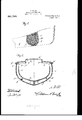
- Fig. 2 is a transverse section through the same on an enlarged scale showing wooden fenders arranged upon the same.
- Fig. 3 is a longitudinal section through the same.
- Fig. 4 is a detail longitudinal section through the keelson showing the manner of securing the frames to the same.
- Fig. 5 is a detail view showing a slightly modified form in which stanchions are employed for strengthening the hull7 and
- Fig. 6 is a detail View of one of the. frames showing the manner of securing the network thereto.
- the frames are formed with integral deck beams A when the size of thc body is not too great to allow the same to be molded and handled readily, but if too greatin size, the frames for each side and the deck beam can be molded separately and connected by binding the reinforcing rods together.
- the complete frames are then placed in the building slip, suitably spaced apart. and braced as in the ordinary manner of shipbuilding so as to hold the same in their proper positions in order to complete the construction of the hull.
- Stem and stern posts D and E which have been molded in a similar manner are then placed in position and the posts are also provided with longitudinal reinforcing rods D, E bound together by zigzag rods D2, E2 which project out through the edges to form similar eyes for securing the network.
- the longitudinal reinforcing rods D, E of these posts project out beyond the lower ends of the posts and pass through openings in the heel of the adjacent frames which are formed when the frames are molded and these rods are bound by tie rods F to longitudinal keelson reinforcing rods F which extend through similar openings formed in the.
- a keelson G is then molded over the reinforcing wires F and adjacent parts of the heel of the frames by a suitably constructed mold of such a size to give the required strength.
- the whole skeleton frame is then covered by a tine wire network or metal lathing H through which t-he outside eyes of the frames, posts and beams project.
- Continuous longitudinal rods I are then run through the eyes of the respect-ive members and have their abutting ends fastened together so as to securely fasten the network in position forming reinforcing members for the shell J and these rods are connected to transverse intermediate reinforcing rods K arranged between the frames which is formed by covering the network and rods upon their inner and outer sides with cement of the required thickness.
- stanchions S When it is necessary to strengthen the hull stanchions S can be employed as clearly shown in the modification, and these stanchiens are molded out of reinforced concrete and are provided with openings adjacent their lower ends through which the longit-udinal reinforcing stringer rods are adapted to pass for securing the same in their proper positions, and it will be seen that these stanchions will strengthen the hull in such a manner that an exceptionally strong boat will be formed.
- a floating body comprising a hull formed of reinforced concrete frames, posts and keelson, eyes projecting out from said frames, posts and keelson, and a reinforced shell secured on said hull by said eyes.
- a floating body comprising a hull formed of molded reinforced frames, posts and keelson molded together having projecting eyes, a wire netting arranged over said hull and secured thereto by rods pas.'- ing through said eyes, and a shell molded over said wire netting.
- a floating body having a skeleton frame formed with projecting eyes, a network through which said eyes project, rods passing through said eyes over said network, and a cement cover arranged over said network and rods.
- a reinforced concrete floating body formed of molded frames provided with reinforcing members projecting out beyond their edges, molded stem and stern posts formed of concrete having reinforcing members projecting out beyond their edges, a keelson molded to said frames and posts provided with reinforcing members connected to the reinforcing members of said posts, a wire network arranged over the said posts and frames, ro-ds passing through the reinforcing members of said frames and posts over said network and a covering of cement arranged over said network and rods.
- a floating body comprising a skeleton frame compo-sed of reinforced concrete frames and stem and stern posts said frames and posts having reinforcing members projecting out beyond their edges, a line network arranged over said skeleton frame, rods passing through the reinforcing members of said frames and posts over said network, intermediate rods connecting said rods and a covering of cement arranged over said network and rods.
- a flo-ating body having a skeleton frame formed of reinforced concrete, the frames and stem and stern posts of said body being provided with outwardly projecting eyes, a network arranged over said skeleton frame, continuous rods passing through said eyes over said network, and a covering of cement arranged over said network and rods.
- a floating body having frames and stem and stern posts provided with longitudinal reinforcing rods connected together by zigzag rods which project out beyond the edges of said members to form eyes, a network arranged over said posts and frames, and rods passing through said eyes over said network.
- a floating body comprising a hull formed of reinforced concrete frames, lreeling portions, and a shell molded on said Wire son, stein and stern posts, Said frames having netting. zig-zuig reinforcing rods projecting out be yond the edges, a net Work of Wire ar- AXEL HOLM.
Landscapes
- Chemical & Material Sciences (AREA)
- Engineering & Computer Science (AREA)
- Combustion & Propulsion (AREA)
- Mechanical Engineering (AREA)
- Ocean & Marine Engineering (AREA)
- Manufacturing Of Tubular Articles Or Embedded Moulded Articles (AREA)
Description
A. HOLM.
CONCRETE FLOATING BODY.
APPLICATION FILED Nov. x, 19cm Patented May 9, 1911.
Z SHEETS-SHEET 1.
me NoRms Fnrrws un., wAsHnmwN. D. c,
A. HOLM.
CONCRETE YLOTNG BODY.
APPLICATION ULEB Nnv.1,1909.
Patented May 9, 1911.
2 BHEETS-SIIEET 2.
AXEL HOLM, OF CAMDEN, NEW JERSEY.
CONCRETE FLOATING BODY.
Specification of Letters Patent.
Application filed November 1, 1909.
Patented May 9, 1.911.
Serial No. 525,729.
To all wle/0m it may concern:
Be it known that IJ Axnr. llomrr, a subject of the King of Denniark, residing at Camn den, in the county of Camden and State of New Jersey1 have iiivented a ne f and useful In'iprovenient in Concrete liloating Bodies, of which the following `is a specification.
rl`his ii'ivcntion relates to certain new aud useful in'iprovements in constructing and building ships and floating bodies of all kinds, the object being to form a floating` body out of reinforced concrete which will be very strong and durable and one which can be constructed at a very low cost.
Another object of my invention is to provide a iioating body in which the hull is formed of molded concrete fran'ies and posts joining to a keelson which is molded after the frames and posts have been positioned in the building slip.
A further object of my invention is to provide novel means for securing the shell of the hull to the skeleton frame whereby the same will be secured thereon in such a manner that the securing means will form reinforcing members.
A still further object. of my invention is to provide a iioating body which is formed of reinforced concreto in such a manner that lthe frames, posts, stringers and keclson will be so united that a solid skeleton frame will be formed so that the strength of the saine is greatly increased.
'With these various objects in view, my invention consists in the novel features of construction, arrangement and combination of parts, all of which will be hereinafter fully described and pointed out in the claims.
In the drawings forming a part o-f this specification: Figure l is a perspective view of a boat constructed in accordance with my invention. Fig. 2 is a transverse section through the same on an enlarged scale showing wooden fenders arranged upon the same. Fig. 3 is a longitudinal section through the same. Fig. 4 is a detail longitudinal section through the keelson showing the manner of securing the frames to the same. Fig. 5 is a detail view showing a slightly modified form in which stanchions are employed for strengthening the hull7 and Fig. 6 is a detail View of one of the. frames showing the manner of securing the network thereto.
In carrying out. my in'iproved invention, I ei'l'iploy a plurality of frames A which' are lormed from regular body plans in suitable molds, each frame having longitudinal reinforeing rods li en'ibedded therein and bound together by a zigzag rod C which projects out beyond the inner and outer edges of the frames so as to form spaced eyes C' for securing the inner ceiling and the outer reinforcing shell network thereto as will be hereinafter fully described. The frames are formed with integral deck beams A when the size of thc body is not too great to allow the same to be molded and handled readily, but if too greatin size, the frames for each side and the deck beam can be molded separately and connected by binding the reinforcing rods together. The complete frames are then placed in the building slip, suitably spaced apart. and braced as in the ordinary manner of shipbuilding so as to hold the same in their proper positions in order to complete the construction of the hull. Stem and stern posts D and E which have been molded in a similar manner are then placed in position and the posts are also provided with longitudinal reinforcing rods D, E bound together by zigzag rods D2, E2 which project out through the edges to form similar eyes for securing the network. The longitudinal reinforcing rods D, E of these posts project out beyond the lower ends of the posts and pass through openings in the heel of the adjacent frames which are formed when the frames are molded and these rods are bound by tie rods F to longitudinal keelson reinforcing rods F which extend through similar openings formed in the.
heel of theintermediate frames. A keelson G is then molded over the reinforcing wires F and adjacent parts of the heel of the frames by a suitably constructed mold of such a size to give the required strength. The whole skeleton frame is then covered by a tine wire network or metal lathing H through which t-he outside eyes of the frames, posts and beams project. Continuous longitudinal rods I are then run through the eyes of the respect-ive members and have their abutting ends fastened together so as to securely fasten the network in position forming reinforcing members for the shell J and these rods are connected to transverse intermediate reinforcing rods K arranged between the frames which is formed by covering the network and rods upon their inner and outer sides with cement of the required thickness. The inner and outer faces of sai d shell are then rubbed down so as to obtain an exceedingly smooth surface for preventing the fouling of the same by the water and to prevent the shell from absorbing water. Longitudinal reinforcing rods L are then passed through the openings formed in the frames at the bilge which have their ends connected to the stem and stern posts over which are molded stringers M in a similar manner as the keelson so as to give the required strength. Deck stringers N are then molded over the longitudinal reinforcing rod N in a similar manner. Longitudinal reinforcing rods O are then passed through the frame and over which are molded deck stringers O and if desired wooden fenders P can be secured in position by U-shaped beams as clearly shown on the outside of the shell and similar bilge fenders can be used if desired so as to protect the shell as much as possible. l/Vhen the deck stringers are molded the central stringers are formed with a hatchway as clearly shown at Q which is adapted to be closed by a cover Q as clearly shown, but it is of course understood that any number of these hatchways can be employed or dispensed with as desired. A ceiling R- of either wood or reinforced cement is then placed in proper position within the hull on the frame and bound by the eyes in any suitable manner so as to form a false bottom for the boat to support the cargo.
When it is necessary to strengthen the hull stanchions S can be employed as clearly shown in the modification, and these stanchiens are molded out of reinforced concrete and are provided with openings adjacent their lower ends through which the longit-udinal reinforcing stringer rods are adapted to pass for securing the same in their proper positions, and it will be seen that these stanchions will strengthen the hull in such a manner that an exceptionally strong boat will be formed.
Having thus fully described my invention, what I claim as new and desire to secure by Letters Patent, is:
l. A floating body comprising a hull formed of reinforced concrete frames, posts and keelson, eyes projecting out from said frames, posts and keelson, and a reinforced shell secured on said hull by said eyes.
2. A floating body comprising a hull formed of molded reinforced frames, posts and keelson molded together having projecting eyes, a wire netting arranged over said hull and secured thereto by rods pas.'- ing through said eyes, and a shell molded over said wire netting.
A floating body having a skeleton frame formed with projecting eyes, a network through which said eyes project, rods passing through said eyes over said network, and a cement cover arranged over said network and rods.
4. As a new article of manufacture, a reinforced concrete floating body formed of molded frames provided with reinforcing members projecting out beyond their edges, molded stem and stern posts formed of concrete having reinforcing members projecting out beyond their edges, a keelson molded to said frames and posts provided with reinforcing members connected to the reinforcing members of said posts, a wire network arranged over the said posts and frames, ro-ds passing through the reinforcing members of said frames and posts over said network and a covering of cement arranged over said network and rods.
5. A floating body comprising a skeleton frame compo-sed of reinforced concrete frames and stem and stern posts said frames and posts having reinforcing members projecting out beyond their edges, a line network arranged over said skeleton frame, rods passing through the reinforcing members of said frames and posts over said network, intermediate rods connecting said rods and a covering of cement arranged over said network and rods.
6. A flo-ating body having a skeleton frame formed of reinforced concrete, the frames and stem and stern posts of said body being provided with outwardly projecting eyes, a network arranged over said skeleton frame, continuous rods passing through said eyes over said network, and a covering of cement arranged over said network and rods.
7. A floating body having frames and stem and stern posts provided with longitudinal reinforcing rods connected together by zigzag rods which project out beyond the edges of said members to form eyes, a network arranged over said posts and frames, and rods passing through said eyes over said network.
8. The combination with a skeleton frame formed of reinforcing concrete having frames and stem and stern posts provided with zigzag reinforcing rods projecting out beyond the edges of said members to form eyes, of a network arranged over said eyes, rods passing through said eyes from said network, and a covering of cement arranged over said network and rods.
9. A floating body comprising a hull formed of reinforced concrete frames, lreeling portions, and a shell molded on said Wire son, stein and stern posts, Said frames having netting. zig-zuig reinforcing rods projecting out be yond the edges, a net Work of Wire ar- AXEL HOLM.
5 ranged over the outwardly projecting por- Witnesses:
tions of the relnforcing rods, rods passlng JAMES F. BAKER, through or under said outwardly project- RALPH D. BAKER.
Copies of this patent may be obtained for five cents each, by addressing the Commissioner of Patents, Washington, D. C.
Priority Applications (1)
| Application Number | Priority Date | Filing Date | Title |
|---|---|---|---|
| US52572909A US991780A (en) | 1909-11-01 | 1909-11-01 | Concrete floating body. |
Applications Claiming Priority (1)
| Application Number | Priority Date | Filing Date | Title |
|---|---|---|---|
| US52572909A US991780A (en) | 1909-11-01 | 1909-11-01 | Concrete floating body. |
Publications (1)
| Publication Number | Publication Date |
|---|---|
| US991780A true US991780A (en) | 1911-05-09 |
Family
ID=3060115
Family Applications (1)
| Application Number | Title | Priority Date | Filing Date |
|---|---|---|---|
| US52572909A Expired - Lifetime US991780A (en) | 1909-11-01 | 1909-11-01 | Concrete floating body. |
Country Status (1)
| Country | Link |
|---|---|
| US (1) | US991780A (en) |
Cited By (2)
| Publication number | Priority date | Publication date | Assignee | Title |
|---|---|---|---|---|
| US2454403A (en) * | 1944-06-26 | 1948-11-23 | Palmieri Mario | Method of constructing concrete vessels |
| US20250153816A1 (en) * | 2023-11-14 | 2025-05-15 | Cabin Air Group B.V. | Factory for Producing an Elongated Tension Member, and Method for Constructing Such a Factory |
-
1909
- 1909-11-01 US US52572909A patent/US991780A/en not_active Expired - Lifetime
Cited By (4)
| Publication number | Priority date | Publication date | Assignee | Title |
|---|---|---|---|---|
| US2454403A (en) * | 1944-06-26 | 1948-11-23 | Palmieri Mario | Method of constructing concrete vessels |
| US20250153816A1 (en) * | 2023-11-14 | 2025-05-15 | Cabin Air Group B.V. | Factory for Producing an Elongated Tension Member, and Method for Constructing Such a Factory |
| US12576950B2 (en) * | 2023-11-14 | 2026-03-17 | Cabin Air Group B.V. | Factory for producing an elongated tension member, and method for constructing such a factory |
| US12668334B2 (en) | 2023-11-14 | 2026-06-30 | Cabin Air Group B.V. | Factory for producing an elongated tension member, and method for constructing such a factory |
Similar Documents
| Publication | Publication Date | Title |
|---|---|---|
| US1073794A (en) | Bridge or ferry. | |
| US250717A (en) | Boat and the method of constructing the same | |
| KR102404985B1 (en) | Fixable assembly barge | |
| US494288A (en) | Portable nesting boat | |
| US387200A (en) | Leak-stopper for ships | |
| US1314069A (en) | Ship construction | |
| US2442A (en) | Floating dry-dock | |
| US1368935A (en) | Non-sinkable ship | |
| US1353235A (en) | Ship construction | |
| US1331604A (en) | Composite vessel | |
| US1255784A (en) | Construction of ships' hulls. | |
| US22175A (en) | Extensible liee-ras | |
| US367828A (en) | mcintyre | |
| US1195727A (en) | Joseph banco | |
| US5368A (en) | Improvement in ship-building | |
| Lavery | Wooden Warship Construction: A History in Ship Models | |
| US1307224A (en) | Concrete structure and method of constructing the same | |
| US1274981A (en) | Reinforced ship. | |
| US1313592A (en) | Ly-mls | |
| US1301270A (en) | Marine-vessel construction. | |
| US1090349A (en) | Boat construction. | |
| US1168926A (en) | Construction of marine vessels. | |
| US198248A (en) | Improvement in ship-building | |
| US230998A (en) | Construction of ships | |
| US403470A (en) | henderson |