US991681A - Carriage-wrench. - Google Patents
Carriage-wrench. Download PDFInfo
- Publication number
- US991681A US991681A US57730110A US1910577301A US991681A US 991681 A US991681 A US 991681A US 57730110 A US57730110 A US 57730110A US 1910577301 A US1910577301 A US 1910577301A US 991681 A US991681 A US 991681A
- Authority
- US
- United States
- Prior art keywords
- bar
- lever
- jaw
- teeth
- wrench
- Prior art date
- Legal status (The legal status is an assumption and is not a legal conclusion. Google has not performed a legal analysis and makes no representation as to the accuracy of the status listed.)
- Expired - Lifetime
Links
Images
Classifications
-
- B—PERFORMING OPERATIONS; TRANSPORTING
- B25—HAND TOOLS; PORTABLE POWER-DRIVEN TOOLS; MANIPULATORS
- B25B—TOOLS OR BENCH DEVICES NOT OTHERWISE PROVIDED FOR, FOR FASTENING, CONNECTING, DISENGAGING, OR HOLDING
- B25B7/00—Pliers; Other hand-held gripping tools with jaws on pivoted limbs; Details applicable generally to pivoted-limb hand tools
- B25B7/12—Pliers; Other hand-held gripping tools with jaws on pivoted limbs; Details applicable generally to pivoted-limb hand tools involving special transmission means between the handles and the jaws, e.g. toggle levers, gears
Definitions
- This invention relates to an improved wrench, particularly adapted to be used in connection with nuts such as the nuts on carriage axles and the like.
- the object of the invention is to provide a wrench which is strong and durable and which can be manufactured cheaply and in which there are no loose or detachable parts.
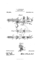
- Figure 1 is a front elevation of my improved wrench, the jaw operating lever being shown in two positions, one in full lines, the other in broken and dotted lines.
- Fig. 2 is a side elevation of the same.
- Fig. 3 is a perspective view of the slidable jaw.
- Fig. 4 is a sectional elevation taken on line 4 4 of Fig. 1.
- A is the wrench bar which is formed of a metal strip bent intermediate its ends to form a U.
- the legs A and A of the wrench bar are separated one from the other by a slot A
- the free ends of the legs A and A have inserted therebetween a block F, constituting a handle, said legs A and A and the block F being rigidly fastened together by rivets A
- a bracket A extends through the slot A between the legs A and A and is rigidly fastened thereto by means of a rivet A. This bracket A thus forms, in effect, a portion of the bar A, it being rigidly fastened thereto.
- the wrench is provided with two jaws B and C.
- the jaw B is slidably mounted upon the bar A and extends through the slot A having two teeth H and H and stops H thereon.
- the tooth H extends entirely across the rear end of the jaw B and is adapted to engage teeth A A formed upon the edges of the legs A and A
- a spiral spring G is fastened to the jaw B and is located between the opposite legs A and A of the bar A, the free end of said spring Gr bearing against the side of the leg A opposite to that upon which the teeth A are out, the tooth H bearing against the same side of said leg A and a like tooth H upon the opposite face of the jaw B bearing against the edge of the leg A
- the action of the spring G is to cause the tooth H to be kept in engagement with the teeth A A while at the same time the teeth H, H, engage the opposite sides of the legs A and A to that upon which the teeth A are located.
- Stops H on opposite sides of the jaw B bear against the edges of the legs A and A opposite to that upon which the teeth A are cut, when the jaw B istipped against the action of the spring to disengage the tooth H from the teeth A A
- the other jaw C forms a part of a lever C which is pivoted at C to the bar A, the jaw G constituting one arm of the lever, the other arm C being formed upon a curve eccentric to the pivot D of a lever D, which lever is pivoted to the bracket A at D.
- the curved or cam-shaped arm 0 extends through a slot D formed between the opposite sides D and D of the lever D.
- the lever D is formed of a strip of metal bent to form a U, the free ends of which are pivoted by the pin D to the bracket A and this lever has two pins D D extending transversely thereof from one leg D to the other leg D*.
- the arm 0 extends through the slot D between the pins D, D and thus slidably engages the lever D, so that when the lever D is rocked upon its pivot D it will rock the lever G upon its pivot C and thus move the jaw C toward or away from the jaw B from the position indicated in dotted lines to the position indicated in full lines and vice versa.
- the distance to which the lever D can be rocked upon its pivot D is limited by the free end of said lever abutting against the bar A.
- a handle E rotatably mounted upon a stud E fast to the bracket A is provided by means of which the wrench may be rotated after the jaws B and C are clamped to a nut.
- jaws B and C are Vshaped on their opposing faces, in order that the same may securely engage opposite corners of the nut which is to be manipulated.
- the lever D is swung outwardly from the handle from the position shown in full lines (Fig. 1) toward that illustrated in dotted lines therein.
- a wrench having, in combination, a bar, a jaw thereon, a lever pivoted to said bar, a second lever extending transversely of said bar and pivoted thereto, one arm of said lever constituting a jaw, the other arm slidably interengaging and eccentric to said first-named lever, whereby said jaw lever may be rocked upon its pivot.
- a wrench having, in combination, a bar, a jaw thereon, a lever pivoted to said bar, a second lever extending transversely of said bar and pivoted thereto, one arm of said lever constituting a aw, the other arm having a cam-shaped form and slidably interengaging said first-named lever, whereby said aw lever may be rocked upon its pivot.
- a wrench having, in combination, a bar, a jaw thereon, a lever pivoted to said bar provided with a slot, a second lever extending transversely of said bar and pivoted thereto, one arm of said lever constituting a jaw, the other arm extending through said slot and eccentric to said first-named lever, whereby said jaw lever may be rocked upon its pivot.
- a wrench having, in combination, a bar with teeth on one side thereof and two jaws thereon, one of said jaws slidably mounted on said bar and extending through a slot provided in said bar and having two teeth diagonally located on opposite sides thereof, one of said teeth adapted to engage one side of said bar, the other tooth adapted to engage the teeth on said bar.
- a wrench having, in combination, a bar with teeth on one side thereof and two jaws thereon, one of said jaws slidably mounted on said bar and extending through a slot provided in said bar and having two teeth diagonally located on opposite sides thereof, one of said teeth adapted to engage one side of said bar, the other tooth adapted to engage the teeth on said bar, and a spring fast to said last-named jaw adapted to hold said last-named aw in engagement with the teeth on said bar.
- a wrench having, in combination, a bar with teeth on one side thereof and two jaws thereon, one of said aws slidably mounted on said bar and extending through a slot provided in said bar and having two teeth diagonally located on opposite sides thereof, one of said teeth adapted to engage one side of said bar, the other tooth adapted to engage the teeth on said bar, and a stop on said last-named jaw adapted to engage the side of said bar opposite to that side which is provided with teeth and a spring fast to said last-named jaw adapted to hold the same in engagement with the teeth on said bar.
- a wrench having, in combination, a bar with teeth on one side thereof, a jaw slidably mounted on said bar and extending through a slot provided in said bar and "having two teeth diagonally located on opposite sides thereof, one of said teeth adapted to engage one side of said bar, the other tooth adapted to engage the teeth on said bar, a lever pivoted to said bar, and a second lever extending transversely of said bar and pivoted thereto, one arm of said lever constituting a aw, the other arm slidably interengaging and eccentric to said first-named lever, whereby said jaw lever may be rocked upon its pivot.
- a wrench having, in combination, a bar consisting of a metal strip bent intermediate its ends to form a U, a bracket extending through between the legs of said U and rigidly fastened thereto, a lever formed of a strip of metal bent to form a U, the free ends of said lever-U being pivoted to said bracket, two pins on said lever-U extending transversely thereof from one leg of said lever-U to the other, a second lever extending transversely of said bar and pivoted thereto, one arm of said second lever constituting a jaw, the other arm slidably interengaging and eccentric to said firstnamed lever, whereby said jaw lever may be rocked upon its pivot, another jaw slidably mounted on said bar, and means to lock said last-named jaw to said bar.
- a wrench having, in combination, a
Landscapes
- Engineering & Computer Science (AREA)
- Mechanical Engineering (AREA)
- Details Of Spanners, Wrenches, And Screw Drivers And Accessories (AREA)
Description
G. A. WINGHENBAGH. GARRIAGE WRENCH. APPLIOATION FILED AUG. 15, 1910.
991,681 Patented Maw, 1911.
CHESTER A. WINCI-IENBAGH, 0F WALIDOBOR-O, MAINE.
CARRIAGE-WRENCH.
Specification of Letters Patent.
Patented May 9, 1911.
Application filed August 15, 1910. Serial No. 577,301.
To all whom it may concern:
Be it known that I, CHESTER A. WINOHEN- BACH, a citizen of the United States, residing in Waldoboro, in the county of Lincoln and State of Maine, have invented a new and convenient Carriage-Trench, of which the following is a specification.
This invention relates to an improved wrench, particularly adapted to be used in connection with nuts such as the nuts on carriage axles and the like.
The object of the invention is to provide a wrench which is strong and durable and which can be manufactured cheaply and in which there are no loose or detachable parts.
The invention consists in the combination and arrangement of parts set forth in the following specification and particularly pointed out in the claims thereof.
Referring to the drawings: Figure 1 is a front elevation of my improved wrench, the jaw operating lever being shown in two positions, one in full lines, the other in broken and dotted lines. Fig. 2 is a side elevation of the same. Fig. 3 is a perspective view of the slidable jaw. Fig. 4: is a sectional elevation taken on line 4 4 of Fig. 1.
Like numerals refer to like parts throughout the several views of the drawings.
In the drawings, A is the wrench bar which is formed of a metal strip bent intermediate its ends to form a U. The legs A and A of the wrench bar are separated one from the other by a slot A The free ends of the legs A and A have inserted therebetween a block F, constituting a handle, said legs A and A and the block F being rigidly fastened together by rivets A A A bracket A extends through the slot A between the legs A and A and is rigidly fastened thereto by means of a rivet A. This bracket A thus forms, in effect, a portion of the bar A, it being rigidly fastened thereto.
The wrench is provided with two jaws B and C. The jaw B is slidably mounted upon the bar A and extends through the slot A having two teeth H and H and stops H thereon. The tooth H extends entirely across the rear end of the jaw B and is adapted to engage teeth A A formed upon the edges of the legs A and A A spiral spring G is fastened to the jaw B and is located between the opposite legs A and A of the bar A, the free end of said spring Gr bearing against the side of the leg A opposite to that upon which the teeth A are out, the tooth H bearing against the same side of said leg A and a like tooth H upon the opposite face of the jaw B bearing against the edge of the leg A The action of the spring G is to cause the tooth H to be kept in engagement with the teeth A A while at the same time the teeth H, H, engage the opposite sides of the legs A and A to that upon which the teeth A are located.
Stops H on opposite sides of the jaw B, one of which stops is shown in Figs. 1 and 3, bear against the edges of the legs A and A opposite to that upon which the teeth A are cut, when the jaw B istipped against the action of the spring to disengage the tooth H from the teeth A A When the jaw B has thus been tipped to disengage the tooth H from the teeth A the same may be slid along the bar A toward the handle or away therefrom, and when the jaw B is released, the spring G will cause the tooth H to engage the teeth A and lock said jaw against movement toward the right 1.) The other jaw C forms a part of a lever C which is pivoted at C to the bar A, the jaw G constituting one arm of the lever, the other arm C being formed upon a curve eccentric to the pivot D of a lever D, which lever is pivoted to the bracket A at D. The curved or cam-shaped arm 0 extends through a slot D formed between the opposite sides D and D of the lever D.
The lever D is formed of a strip of metal bent to form a U, the free ends of which are pivoted by the pin D to the bracket A and this lever has two pins D D extending transversely thereof from one leg D to the other leg D*. The arm 0 extends through the slot D between the pins D, D and thus slidably engages the lever D, so that when the lever D is rocked upon its pivot D it will rock the lever G upon its pivot C and thus move the jaw C toward or away from the jaw B from the position indicated in dotted lines to the position indicated in full lines and vice versa. The distance to which the lever D can be rocked upon its pivot D is limited by the free end of said lever abutting against the bar A.
A handle E, rotatably mounted upon a stud E fast to the bracket A is provided by means of which the wrench may be rotated after the jaws B and C are clamped to a nut.
It will be noted that the jaws B and C are Vshaped on their opposing faces, in order that the same may securely engage opposite corners of the nut which is to be manipulated.
I-laving now specifically described my invention, I will proceed to describe the manner in which the same may be used. The jaw C is placed against one corner of the nut which is to be turned and the jaw B is slid up against the diagonally opposite corner by tipping said aw until the tooth H is disengaged from the teeth Ahthenmoving the aw longitudinally of the bar A. in the desired direction, the V-shaped engaging face of the aw B is brought into engagement with one corner of the nut which is to be manipulated and then released, when it is snapped back into position with the tooth H engaging the teeth it by the spring G. A final and strong grip of the jaws upon the nut is obtained by swinging the lever D upon its pivot D from the position shown in dotted lines (Fig. 1) toward the position shown in full lines therein until the desired grip of the jaws C and B upon the nut is obtained.
To release the jaws from the nut, the lever D is swung outwardly from the handle from the position shown in full lines (Fig. 1) toward that illustrated in dotted lines therein.
Where nuts of the same size are being operated upon with the wrench, the operation hereinbefore described for changing the distance of the jaw 13 from. the jaw C is unnecessary, and only the rocking movement of the jaw C by means of the lever D, as hereinbefore described, is necessary to grip or release the nut.
Having thus described my invention, what I claim and desire by Letters Patent to secure is:
1. A wrench having, in combination, a bar, a jaw thereon, a lever pivoted to said bar, a second lever extending transversely of said bar and pivoted thereto, one arm of said lever constituting a jaw, the other arm slidably interengaging and eccentric to said first-named lever, whereby said jaw lever may be rocked upon its pivot.
2. A wrench having, in combination, a bar, a jaw thereon, a lever pivoted to said bar, a second lever extending transversely of said bar and pivoted thereto, one arm of said lever constituting a aw, the other arm having a cam-shaped form and slidably interengaging said first-named lever, whereby said aw lever may be rocked upon its pivot.
3. A wrench having, in combination, a bar, a jaw thereon, a lever pivoted to said bar provided with a slot, a second lever extending transversely of said bar and pivoted thereto, one arm of said lever constituting a jaw, the other arm extending through said slot and eccentric to said first-named lever, whereby said jaw lever may be rocked upon its pivot.
i. A wrench having, in combination, a-
bar, a jaw thereon, a lever formed of a strip of metal bent to form a U, the free ends of said U being pivoted to said bar, two pins on said lever extending transversely thereof from one leg of said U to the other, a second lever extending transversely of said bar and pivoted thereto, one arm of said lastnamed lever constituting a jaw, the other arm extending through said lever between said pins and curved eccentrically to said firstna1ned lever.
5. A wrench having, in combination, a bar with teeth on one side thereof and two jaws thereon, one of said jaws slidably mounted on said bar and extending through a slot provided in said bar and having two teeth diagonally located on opposite sides thereof, one of said teeth adapted to engage one side of said bar, the other tooth adapted to engage the teeth on said bar.
6. A wrench having, in combination, a bar with teeth on one side thereof and two jaws thereon, one of said jaws slidably mounted on said bar and extending through a slot provided in said bar and having two teeth diagonally located on opposite sides thereof, one of said teeth adapted to engage one side of said bar, the other tooth adapted to engage the teeth on said bar, and a spring fast to said last-named jaw adapted to hold said last-named aw in engagement with the teeth on said bar.
7. A wrench having, in combination, a bar with teeth on one side thereof and two jaws thereon, one of said aws slidably mounted on said bar and extending through a slot provided in said bar and having two teeth diagonally located on opposite sides thereof, one of said teeth adapted to engage one side of said bar, the other tooth adapted to engage the teeth on said bar, and a stop on said last-named jaw adapted to engage the side of said bar opposite to that side which is provided with teeth and a spring fast to said last-named jaw adapted to hold the same in engagement with the teeth on said bar.
8. A wrench having, in combination, a bar with teeth on one side thereof, a jaw slidably mounted on said bar and extending through a slot provided in said bar and "having two teeth diagonally located on opposite sides thereof, one of said teeth adapted to engage one side of said bar, the other tooth adapted to engage the teeth on said bar, a lever pivoted to said bar, and a second lever extending transversely of said bar and pivoted thereto, one arm of said lever constituting a aw, the other arm slidably interengaging and eccentric to said first-named lever, whereby said jaw lever may be rocked upon its pivot.
9. A wrench having, in combination, a bar consisting of a metal strip bent intermediate its ends to form a U, a bracket extending through between the legs of said U and rigidly fastened thereto, a lever formed of a strip of metal bent to form a U, the free ends of said lever-U being pivoted to said bracket, two pins on said lever-U extending transversely thereof from one leg of said lever-U to the other, a second lever extending transversely of said bar and pivoted thereto, one arm of said second lever constituting a jaw, the other arm slidably interengaging and eccentric to said firstnamed lever, whereby said jaw lever may be rocked upon its pivot, another jaw slidably mounted on said bar, and means to lock said last-named jaw to said bar.
10. A wrench having, in combination, a
bar consisting of a metal strip bent intermediate its ends to form a U, a bracket extending through between the legs of said U and rigidly fastened thereto, a handle mounted on said bracket and extending transversely thereof, a lever pivoted to said bracket, a second lever extending transversely of said bar and pivoted thereto, one arm of said lastnan1ed lever constituting a jaw, the other arm slidably interengaging and eccentric to said first-named lever, whereby said jaw lever may be rocked upon its pivot, a jaw slidably mounted on said bar, and means to lock said slidabl-e jaw to said bar.
CHESTER A. l/VINCHENBACH.
WVitnesses C. H. CURTIS, E. S. GRownLL.
Copies of this patent may be obtained for five cents each, by addressing the Commissioner of Patents, Washington, D. C.
Priority Applications (1)
| Application Number | Priority Date | Filing Date | Title |
|---|---|---|---|
| US57730110A US991681A (en) | 1910-08-15 | 1910-08-15 | Carriage-wrench. |
Applications Claiming Priority (1)
| Application Number | Priority Date | Filing Date | Title |
|---|---|---|---|
| US57730110A US991681A (en) | 1910-08-15 | 1910-08-15 | Carriage-wrench. |
Publications (1)
| Publication Number | Publication Date |
|---|---|
| US991681A true US991681A (en) | 1911-05-09 |
Family
ID=3060016
Family Applications (1)
| Application Number | Title | Priority Date | Filing Date |
|---|---|---|---|
| US57730110A Expired - Lifetime US991681A (en) | 1910-08-15 | 1910-08-15 | Carriage-wrench. |
Country Status (1)
| Country | Link |
|---|---|
| US (1) | US991681A (en) |
-
1910
- 1910-08-15 US US57730110A patent/US991681A/en not_active Expired - Lifetime
Similar Documents
| Publication | Publication Date | Title |
|---|---|---|
| US1916556A (en) | Clamp | |
| US1032035A (en) | Pipe-wrench. | |
| US621869A (en) | Monkey-wrench | |
| US749134A (en) | Noah charles hyman | |
| US1520613A (en) | Pliers | |
| US391532A (en) | Wrench | |
| US1082601A (en) | Adjustable wrench. | |
| US242130A (en) | Wrench | |
| US592666A (en) | Monkey-wrench | |
| US615643A (en) | Wrench | |
| US602590A (en) | Pipe-wrench | |
| US459072A (en) | Nut-wrench | |
| US1060391A (en) | Wrench. | |
| US787831A (en) | Nut-wrench. | |
| US758580A (en) | Wrench. | |
| US234091A (en) | Wrench | |
| US606047A (en) | Axle-nut wrench | |
| US205081A (en) | Improvement in pipe-wrenches | |
| US1180301A (en) | Monkey-wrench. | |
| US632603A (en) | Nut-wrench. | |
| US420867A (en) | Wrench | |
| US661187A (en) | Pipe-wrench. | |
| US1034341A (en) | Wrench. | |
| US1003426A (en) | Wrench. | |
| US1309462A (en) | Automatic wrench |