US9915046B2 - Self alignment structure for applications joining extruded members - Google Patents
Self alignment structure for applications joining extruded members Download PDFInfo
- Publication number
- US9915046B2 US9915046B2 US14/968,909 US201514968909A US9915046B2 US 9915046 B2 US9915046 B2 US 9915046B2 US 201514968909 A US201514968909 A US 201514968909A US 9915046 B2 US9915046 B2 US 9915046B2
- Authority
- US
- United States
- Prior art keywords
- decking
- vertical
- webbing
- panel
- members
- Prior art date
- Legal status (The legal status is an assumption and is not a legal conclusion. Google has not performed a legal analysis and makes no representation as to the accuracy of the status listed.)
- Expired - Fee Related, expires
Links
Images


Classifications
-
- E—FIXED CONSTRUCTIONS
- E01—CONSTRUCTION OF ROADS, RAILWAYS, OR BRIDGES
- E01D—CONSTRUCTION OF BRIDGES, ELEVATED ROADWAYS OR VIADUCTS; ASSEMBLY OF BRIDGES
- E01D19/00—Structural or constructional details of bridges
- E01D19/12—Grating or flooring for bridges; Fastening railway sleepers or tracks to bridges
- E01D19/125—Grating or flooring for bridges
-
- B—PERFORMING OPERATIONS; TRANSPORTING
- B21—MECHANICAL METAL-WORKING WITHOUT ESSENTIALLY REMOVING MATERIAL; PUNCHING METAL
- B21C—MANUFACTURE OF METAL SHEETS, WIRE, RODS, TUBES, PROFILES OR LIKE SEMI-MANUFACTURED PRODUCTS OTHERWISE THAN BY ROLLING; AUXILIARY OPERATIONS USED IN CONNECTION WITH METAL-WORKING WITHOUT ESSENTIALLY REMOVING MATERIAL
- B21C23/00—Extruding metal; Impact extrusion
-
- E—FIXED CONSTRUCTIONS
- E01—CONSTRUCTION OF ROADS, RAILWAYS, OR BRIDGES
- E01D—CONSTRUCTION OF BRIDGES, ELEVATED ROADWAYS OR VIADUCTS; ASSEMBLY OF BRIDGES
- E01D21/00—Methods or apparatus specially adapted for erecting or assembling bridges
-
- B—PERFORMING OPERATIONS; TRANSPORTING
- B23—MACHINE TOOLS; METAL-WORKING NOT OTHERWISE PROVIDED FOR
- B23K—SOLDERING OR UNSOLDERING; WELDING; CLADDING OR PLATING BY SOLDERING OR WELDING; CUTTING BY APPLYING HEAT LOCALLY, e.g. FLAME CUTTING; WORKING BY LASER BEAM
- B23K20/00—Non-electric welding by applying impact or other pressure, with or without the application of heat, e.g. cladding or plating
- B23K20/12—Non-electric welding by applying impact or other pressure, with or without the application of heat, e.g. cladding or plating the heat being generated by friction; Friction welding
- B23K20/122—Non-electric welding by applying impact or other pressure, with or without the application of heat, e.g. cladding or plating the heat being generated by friction; Friction welding using a non-consumable tool, e.g. friction stir welding
-
- B—PERFORMING OPERATIONS; TRANSPORTING
- B23—MACHINE TOOLS; METAL-WORKING NOT OTHERWISE PROVIDED FOR
- B23K—SOLDERING OR UNSOLDERING; WELDING; CLADDING OR PLATING BY SOLDERING OR WELDING; CUTTING BY APPLYING HEAT LOCALLY, e.g. FLAME CUTTING; WORKING BY LASER BEAM
- B23K2101/00—Articles made by soldering, welding or cutting
- B23K2101/24—Frameworks
-
- B—PERFORMING OPERATIONS; TRANSPORTING
- B23—MACHINE TOOLS; METAL-WORKING NOT OTHERWISE PROVIDED FOR
- B23K—SOLDERING OR UNSOLDERING; WELDING; CLADDING OR PLATING BY SOLDERING OR WELDING; CUTTING BY APPLYING HEAT LOCALLY, e.g. FLAME CUTTING; WORKING BY LASER BEAM
- B23K2103/00—Materials to be soldered, welded or cut
- B23K2103/08—Non-ferrous metals or alloys
- B23K2103/10—Aluminium or alloys thereof
-
- B23K2201/24—
-
- B23K2203/10—
-
- E—FIXED CONSTRUCTIONS
- E01—CONSTRUCTION OF ROADS, RAILWAYS, OR BRIDGES
- E01D—CONSTRUCTION OF BRIDGES, ELEVATED ROADWAYS OR VIADUCTS; ASSEMBLY OF BRIDGES
- E01D2101/00—Material constitution of bridges
- E01D2101/30—Metal
- E01D2101/34—Metal non-ferrous, e.g. aluminium
Definitions
- the present disclosure relates generally to structures and methods for self-aligning bridge decking members to be joined through various methods including, without limitation, fusion welding, friction stir welding, and mechanical fastening applications.
- Bridge decking is relatively well known.
- bridge decking includes two panels or skins lying in a generally horizontal plane (or other intended plane of roadway), parallel to one another.
- the skins are spaced vertically apart by internal vertical, slanted, trapezoidal, or triangular members similar in nature to the way webbing spaces two horizontal surfaces in I-beams.
- the internal webbing serves to distribute loads imparted on the horizontal surfaces. Additionally, the webbing rigidly resists deflection and torsion resulting from the loads imparted on the horizontal panels.
- Creating bridge decking from lightweight metals, such as aluminum, is advantageous for several reasons. Decreasing the weight of decking in a bridge structure may allow for increased service loads.
- Aluminum bridge decking can be prefabricated in modular units and joined together on site when placed in service. Aluminum bridge decking is more easily transported that heavier metals or preformed concrete. Aluminum bridge decking may be employed in new structures, or it may be used to refurbish an aging bridge structure.
- Modular bridge decking members are typically joined at their vertical seam abutments by various welding, filling, or fastening methods. Welding the decking faying surfaces (abutments) typically provides for more rigidity and increased load distribution, whereas non-welded fasteners allow enhanced and semi or fully-independent movement as between modular decking members under changing load conditions. In applications where welded joints are desired, the use of friction stir welding (“FSW”) techniques has developed as one possible method for joining the members.
- FSW friction stir welding
- Friction stir welding generally includes the application of a pin or probe to the surface of a joint or seam.
- the pin applies pressure and fiction, typically by spinning, on the seam sufficient to cause the metal of the faying surface to plasticize.
- the pin may be separately heated, but typically is designed to cause the metal to plasticize purely as a result of pressure without the need for additional heat or electricity.
- the pin moves along the length of the faying surface, and the plasticized metals from adjoining members are effectively “stirred” and intermix in the void created by the pin movement, thereby creating a weld seam. Additional filler material is typically unneeded.
- the FSW tool and pin can be precisely calibrated to apply no more than the exact pressure needed to cause the metal to plasticize and weld. This precise calibration also means that the weld joint cools and hardens almost immediately after the pin has passed a point in the faying surface. This results in a relatively instant weld without the application of broader heat, which can cause unwanted deformations.
- the application of force from an FSW pin may be problematic.
- the desire is to join the abutments of horizontal panels in bridge decking
- the application of a pin from above a panel, and the corresponding vertical pressure can cause unwanted deformation in the decking panel.
- developments have included the use of a pin with both an upper and lower shelf on either side of the welding probe.
- the FSW pin is instead applied to the abutment joint from a position parallel to the seam (i.e., from the side of the panel). Through this orientation, force perpendicular to the plane of panel is removed.
- Said dual-shoulder arrangement is described, for example, in U.S. Patent Publication No.
- having a second shoulder on the distal end of a welding pin means that abutments must be located in flanged areas of the decking free from any obstructions intersecting with the flanged panels.
- This limitation means that the weld area is located in a region of the decking that is less stable as compared to other possible locations. For example, if it is possible for the faying surface to be in a location of the decking at, or close to the intersection of internal deck webbing members, the welds would be subject to a smaller torque moment, because the shorter span to transfer vertical load to the webbing members.
- Aluminum decking panels are typically extruded or rolled. Although current methods for manufacturing aluminum decking are relatively precise, inconsistencies persist nonetheless. For example, aluminum panels may vary somewhat in thickness or extend away from webbing intersections at slight angles. Thus, when the decking members are intended to be joined at the abutments, these inconsistencies can make welding difficult.
- the self-alignment structure is a single bridge decking member that is may be replicated and thereafter interconnected.
- improvements of the self-alignment structure can all be found in a single bridge decking member.
- the improvements of the self-aligning structure disclosed herein may be employed between members of dissimilar shapes, for example a decking member with greater width may be self-aligned through the alignment structure with another decking member having a smaller width.
- a decking member used for a central part of a bridge or roadway may have certain physical characteristics and/or spatial geometries which differ from other members used for distal regions of a bridge which may accommodate shoulders, gutters, or guardrails. Nonetheless, such differing members can be interconnected through the use of the self-alignment structures disclosed herein.
- these embodiments employ a self-alignment structure comprising one or more bridge decking members including and upper panel and a lower panel connected by webbing members therebetween.
- One side of the bridge decking member may have a void space between the upper panel and lower panel and an other side the decking member may have a vertical webbing member between the upper panel and the lower panel.
- the self aligning structure may further include an upper shelf and lower shelf, each extending horizontally away from the vertical webbing member, operable to align a neighboring decking member, thereby forming abutment joints in preparation for the application of a friction stir welding tool.
- the self-alignment structure is intended to encompass a plurality of self-aligned bridge decking members.
- the various aspects of the improvements disclosed herein are identified as operable relative to one another.
- the self-aligning structure comprises a first bridge decking member and a second decking member, each having an upper panel and a lower panel connected by webbing members therebetween.
- the upper and lower panels of each bridge decking member further comprise flanges which extend away from the center of the decking members. These flanges further comprise ends, which form abutment joints with each flange of the neighboring member.
- the first decking member may further comprise an upper shelf extending horizontally beneath the abutment joint formed by the upper flanges and a lower shelf extending horizontally above the abutment joint formed by the lower flanges.
- the upper and lower shelves may be connected by a vertical webbing member therebetween.
- each decking member may have a void space between the upper panel and lower panel of each decking member, wherein the void space of one decking member is spanned by the vertical webbing member and upper and lower shoulders of the other decking member.
- the upper shelf of the first member may have an upwardly facing horizontal face in contact with the lower surface of the upper flange of the second member.
- the lower shelf of the first member may have a downwardly facing horizontal face that is in contact with the upper surface of the lower flange of the second member.
- FIG. 1 is a vertical elevation view of typical abutment joints in known bridge decking.
- FIG. 2 is an exemplary vertical elevation view of an FSW pin being applied to the surface of an upper panel of a typical abutment joint in known bridge decking with an anvil beneath the upper surface.
- FIG. 3 is an exemplary vertical elevation view of two self-reacting FSW tools applied to both upper panels and lower panels of a typical abutment joint in known bridge decking.
- FIG. 4 is an exaggerated vertical elevation view of known bridge decking suffering vertical deformity resulting from the manufacturing extrusion process.
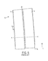
- FIG. 5 is a top plan view of bridge decking members positioned side by side, suffering from both horizontal and axial deformities resulting from the manufacturing extrusion process.
- FIG. 6 is a vertical elevation view of mismatched abutments having thickness differences as between bridge decking panels resulting from the manufacturing extrusion process.
- FIG. 7 is a vertical elevation view of offset abutments resulting from a failure to accurately align decking panels.
- FIG. 8 is a vertical elevation view of bridge decking employing the self-aligning and internal support structure disclosed herein.
- the extrusions are not always identical as there may be a variety of geometries within the same structure.
- FIG. 1 is a vertical elevation view of typical abutment joints in known bridge decking.
- FIG. 1 illustrates a bridge decking arrangement 10 for FSW applications through the extrusion profile.
- FIG. 1 illustrates ideal conditions for joining blunt abutments under the typical bridge decking arrangement for aligning members to be joined via FSW.
- Typical FSW bridge alignment calls for at least a first bridge decking member 12 and a second bridge decking member 14 .
- Each member 12 , 14 comprises at least an upper surface 11 and a lower surface 15 which are separated by internal walls 13 connecting the upper surface 11 to the lower surface 15 .
- either upper or lower surfaces 11 , 15 may be referred to alternatively as upper or lower plates 11 , 15 .
- the internal walls 13 may be referred to as webbing 13 , or internal webbing 13 .
- internal webbing 13 may extend vertically or at an angle as between upper and lower plates 11 , 15 .
- the regions of the upper and lower plates 11 , 15 extending laterally away from the center regions of the plates and intended to abut another bridge decking member are referred to as flanges 16 , 20 .
- each upper flange 16 and each lower flange 20 further comprises a blunt vertical surface 24 .
- each member 12 , 14 are aligned so that each blunt vertical surface 24 of each respective upper and lower flange 16 , 20 are in physical contact prior to the application of FSW.
- the typical member alignment 10 of FIG. 1 is intended for an FSW tool 30 to be applied to weld the blunt vertical surfaces 24 together.
- FIG. 2 is an exemplary vertical elevation view of the application of an FSW pin 32 to upper panels of two bridge decking members.
- the blunt vertical surfaces 24 of each upper and lower flange 16 , 20 may also be referred to as faying surfaces 24 , or collectively, abutment joint 24 .
- the joined region may be referred to as a weld line 24 .
- an FSW tool 30 comprises a pin 32 which imparts vertical and rotational frictional pressure on the faying surface 24 of the upper flange 16 of each bridge decking member 12 , 14 .
- an anvil 34 has been temporarily placed beneath the upper flanges 16 of each bridge decking member 12 , 14 .
- the anvil 34 further distributes the vertical pressure from the FSW tool 30 to the lower panels 15 of each bridge decking member 12 , 14 and thereon to any surface by which the members 12 , 14 are supported (not depicted).
- the members 12 , 14 and the FSW tool 30 must move in opposite directions relative to one another. Effectively, the FSW tool traverses across the members 12 , 14 . In the embodiment of FIG. 2 , for example, the FSW tool 30 moves along the path of the faying surface 24 in the direction of the extrusion profile.
- either a second FSW tool 30 is required to join the faying surfaces 24 of the lower flanges 20 , or else, (i) the FSW tool must be able to articulate beneath the members 12 , 14 , or (ii) the decking members 12 , 14 must be rotated over to the other side and realigned so the FSW tool 30 can be reapplied.
- each FSW tool 40 comprises a “self-reacting” pin (not visible).
- a self-reacting FSW tool 40 generally refers to an FSW tool having a proximal shoulder 42 and a distal shoulder 44 and a self-reacting pin (not visible) therebetween.
- the self-reacting pin of FSW tool 40 is not visible in FIG. 4 because it has progressed deeper into the extrusion profile of the faying surface, leaving only the weld line 24 of the joined flanges 16 , 20 of the members 12 , 14 in view.
- the shoulders 42 , 44 of the self-reacting FSW tool 40 obviate the need for a support anvil, as seen in FIG. 2 , because the pressure imparted on the flanges 16 , 20 of the upper and lower panels 14 , 15 is not vertical. Instead, the self-reacting FSW tool 40 engages the flanges 16 , 20 laterally and imparts pressure in direction of the plane of the faying surface 24 . Accordingly, the flanges 16 , 20 , are not subject to a normal force and don't suffer from a bending moment.
- Each shoulder 42 , 44 of the self reacting tool 40 is in close contact with the surfaces of the flanges 16 , 20 which prevents the plasticized material from spreading away from from the weld line 24 .
- the shoulders 42 , 44 of the self reacting FSW tool 40 aim to ensure a more consistent weld line 24 and an overall stronger connection.
- FIG. 4 is a vertical elevation view of the horizontal length L of typical bridge decking suffering an exaggerated vertical deformity 50 as a result of the extrusion manufacturing process.
- the typical aluminum extrusion process is relatively precise, certain inconsistencies remain. For example, differences in material composition may exist as between one piece of raw material and another. Also, finished extruded members may be grouped together although they may have come from different source batches of raw materials. The extrusion process further imparts heat and pressure in forcing the raw materials through a desired die configuration. Any of the foregoing factors may influence a final member with geometric imperfections, such as vertical deformities, oscillations, twists, and turns.
- the length of the extrusion profile L is seen in a generally horizontal plane.
- vertical deformation D V is the distance by which a portion of the member has deflected vertically as compared to a reference point on the member.
- the central region of the member 12 has deflected vertically downward as compared to the end regions causing vertical deformation D V .
- Vertical deformation D V can further be caused by or worsen as a consequence of vertical pressure imparted on the member 12 from an FSW tool 30 and translating along the length L of the abutment joints 24 .
- Vertical deformity D V can be caused or worsen as a consequence of the plasticized material hardening along a weld line 24 .
- an FSW pin 32 of an FSW tool 30 is applied vertically to the abutment joint 24 of the flanges 16 of upper panels 11 between a first member 12 and second member 14 .
- the FSW pin 32 thereon plasticizes material on the faying surface 24 .
- the FSW tool 30 and pin 32 translate through the extrusion profile, along length L.
- the void space created by translation of the FSW pin 32 is filled both by the intermixing of the plasticized material, as well as the lateral pressure imparted by outside alignment forces.
- the material constricts, which creates tension on the upper flange 16 of panel 11 . Because flange 16 of the upper panel 11 has less depth as compared to width, the panel tends to deform upwardly as the cooling of plasticized material creates tension.
- Vertical deformity D V is undesirable when constructing bridge decking because it results in further mismatches at other abutments as additional members are added to the decking. Moreover, Vertical deformities create problems related to other materials added to create a finished road surface. Vertical deformities can additionally cause water to pool in areas of the decking after rain evens or cause for pockets of snow to harden, which can result in an unsafe road conditions for drivers.
- FIG. 5 is a plan view of the of the horizontal length L of typical bridge decking suffering an exaggerated horizontal deformity 70 as a result of the extrusion manufacturing process.
- the length of the extrusion profile L along a horizontal plane is seen from a plan view perspective.
- the top panels 11 of the first member 12 and second member 14 are in view. Additionally visible between the top panels is a completed FSW weld line 24 running the length of length L between members 12 and member 14 along the flanges 16 , which have now been joined.
- Cut line A-A defines the plane by which embodiments herein are viewed through the extrusion profile, such as in FIGS. 1, 2, 3, 6, 7, and 8 .
- vertical deformation D H is the distance by which the members have deflected horizontally as compared to a reference point.
- the central region of the members 12 , 14 have deflected horizontally outward as compared to the end regions, causing horizontal deformation D H .
- horizontal deformation D H can also form or be aggravated by outside alignment pressure imparted on the members 12 , 14 .
- outside pressure is imparted on the members 12 , 14 to align the abutment joints 24 .
- the upper panels 11 are in compression.
- a traditional or self-reacting FSW tool 30 , 40 is applied and thereafter translated along the length L of the abutment joints 24 , the weld areas begin to plasticize, intermix, and fill the void space left by the FSW pin.
- plasticized areas do not counteract compressive forces imparted through the panels 11 as well as hardened areas, some movement occurs. Also, because only small areas are experiencing plasticization at any given time (i.e. the FSW pin only causes a local region to plasticize), only that area will be vulnerable to movement as a result of outside compressive alignment forces. Thus, as the FSW tool translates on the length L of the abutment joints, small movements occur as the faying surfaces 24 of the members 12 , 14 intermix and cool to form weld lines 24 . Because theses small movements do not occur uniformly across the length L of the members 12 , 14 it results in an ongoing series of local area movement caused by outside compressive forces.
- the local area movement can cause the remaining regions of the members 12 , 14 to mis-align.
- additional compressive forces are needed to maintain the abutment joints 24 in contact, which causes bending, and whereupon local plasticization and subsequent cooling, fuses the horizontal deformity D H in place.
- the extrusion manufacturing process may cause panels to experience axial deformity D A .
- Many extrusion manufacturing processes include the application of cutting devices, which are applied to extruded members simultaneously traveling across one or more conveyor belts. Accordingly, such processes can introduce additional imperfections which may cause the lengths of members to be inconsistent.
- Axial deformity D A is the distance by which the length L of a first member 12 extends beyond the length L of a second member 14 .
- Axial deformity D A can also result from the horizontal deformity D H of the joined panels.
- Horizontal deformity D H may result in members 12 , 14 being curved. Just as the perimeter of a circle will be greater the larger its radius, likewise, an outer curved member 14 would have to be longer to span the same arc angle covered by an inner curved member 12 . However, because members 12 , 14 are of equal lengths, the curve imparted by horizontal deformity D H may also result in axial deformity D A as between the inside curved member 12 and outside curved member 14 .
- Axial deformities D A and horizontal deformities D H are undesirable when constructing bridge decking because they result in further mismatches with other abutments as additional members are added to the decking.
- the self-aligning structures disclosed herein serve to overcome the weld alignment problems caused by such deformities and therefore permit for greater consistency in the application of such welds.
- the abutment joint 24 between first member 12 and second member 14 is mismatched because the flange 28 of second member 14 is thicker than the flange 16 of the first member 12 .
- a mismatched joint can be the result of material imperfections encountered through the manufacturing extrusion process. As viewed through the extrusion profile, the horizontal surface of first member 12 is uneven with the horizontal member of the second surface 14 . This mismatch can create problems joining the members 12 , 14 because when the pin 32 of a traditional FSW tool 30 is applied, the faying surface 24 of the thicker flange 28 will come into contact with the pin 32 prior to the thinner flange 16 , causing the pin to bias to one side of the mismatch.
- the plasticization and intermixing will be inconsistent. Additionally, the thicker flange 28 may prevent the pin 32 of the FSW tool to penetrate all they way through the vertical length of the faying surface 24 . Accordingly, the entire abutment joint may not result in a solid weld.
- a flange thickness mismatch can prevent the proper application of a self-reacting FSW tool 40 as well. Because the shoulders 42 , 44 of a self-reacting FSW tool 40 must be spaced slightly further apart than the thickness of the flanges to which it is applied, a gap will exist between the thinner panel 16 and the shoulders 42 , 44 of a self-reacting FSW tool 40 .
- any gap existing between the flange and either of the shoulders 42 , 44 will effectively render the benefits of a self-reacting FSW tool useless.
- the abutment joint 24 between first member 12 and second member 14 are mismatched because the vertical elevation of first member 12 and second member 14 have not been properly aligned.
- the result is vertical mismatch Y.
- Vertical mismatch is the distance by which a vertical abutment 24 of a first member 12 extends above or below the abutment 24 of a second member 14 .
- each member 12 , 14 has an upper panel that has a predetermined thickness value through which it is desired that an FSW tool imparts a weld, then any vertical mismatch Y, will decrease the thickness of the weld. In other words, the thickness of the welded area at abutment joints 24 will not be as thick as desired.
- any vertical mismatch Y will also be present in the abutment joints 24 of the lower flanges 20 .
- the thickness of the weld area at the abutment joint 24 of the lower flanges 20 is even more greatly decreased, proportional to its original intended thickness.
- a vertical mismatch Y may be relatively insubstantial in comparison to the thicknesses of upper panels 16
- the same vertical mismatch Y can decrease the proportional thickness of the weld line 24 in lower flanges 20 more substantially.
- the self-aligning structure 60 comprises a first bridge decking member 12 having an upper panel 11 and a lower panel 15 connected by webbing members 13 therebetween.
- the self-alignment structure 60 further comprises a second bridge decking member 14 having an upper panel 11 and a lower panel 15 connected by webbing members 13 therebetween.
- the upper panel 11 of each bridge decking member further comprises a flange 16 which extends away from the center of the decking member.
- the lower panel 11 of each member comprises a flange 20 which extends away from the center of the member.
- Each flange 16 , 20 of each upper and lower panel 11 , 15 of each member 12 , 14 further comprises an end, which forms an abutment joint 24 with each flange 11 , 15 of the neighboring member 12 , 14 .
- the first decking member 12 may further comprise an upper 62 shelf extending horizontally beneath the abutment joint formed by the upper flanges 16 and a lower shelf 64 extending horizontally above the abutment joint formed by the lower flanges 20 .
- the upper shelf 62 and lower shelf 64 may be connected by a vertical webbing member 68 therebetween.
- FIG. 8 illustrates each decking member 12 , 14 having a void space 67 between the upper panel 11 and lower panel 15 of each decking member.
- Employing an integral webbing member 68 obviates the need for a support anvil and increases the strength consistency of the joined decking members.
- the void space 67 of the second decking member 14 is filled by the vertical webbing 68 member and upper and lower shelves 62 , 64 of the first decking member 12 .
- the upper shelf 62 of the first decking member 12 may optionally have an upwardly facing horizontal face that is in contact with the lower surface of the upper flange 16 of the second member 14 .
- the lower shelf 64 of the first decking member 12 may optionally have a downwardly facing horizontal face that is in contact with the upper surface of the lower flange 20 of the second member 14 .
- FIG. 8 further disclose the first bridge decking member 12 having webbing members 13 that alternate between an angled position and a vertical position to form a triangle.
- the embodiments depicted in FIG. 8 further disclose the second bridge decking member 14 having webbing members 13 that alternate between an angled position and a vertical position to form a triangle.
- the alignment of the first decking member 12 and second decking member 14 cause for the vertical webbing member 68 connecting the upper and lower shelves 62 , 64 of the first decking member 12 to continue the alternation of angled and vertical webbing 13 positions as between the first and second decking members 12 , 14 .
- the vertical webbing member 68 connecting the upper and lower shelves 62 , 64 of the first decking member 12 forms a triangle in the void space 67 between the first and second decking members 12 , 14 .
- the self-aligning structure 60 for friction stir welding as illustrated by FIG. 8 and discussed above further comprises extruded aluminum.
- the self-aligning structure 60 for friction stir welding as illustrated by FIG. 8 and discussed above optionally employs bridge decking members 12 , 14 having a greater thickness of the upper panels 11 and a lesser thickness of the lower panels 15 .
- FIG. 8 illustrates the alignment of two neighboring decking members 12 , 14
- the present disclosure is not so limited.
- the improvements described herein may be self-contained a single decking member. The intention is that the self-contained decking member may be replicated and thereby sequentially align, optionally in perpetuity. This allows the improvements disclosed herein to be able to scale to meet larger projects.
- the self-aligning structure 60 may comprise a bridge decking member 12 with an upper panel 11 and a lower panel 15 connected by webbing members 13 therebetween.
- One side of the bridge decking member 12 may optionally comprise a void space between the upper panel 11 and the lower panel 15 and an other side of the decking member 12 may have a vertical webbing member 68 between the upper panel 11 and the lower panel 15 .
- the self aligning structure 60 may further comprise an upper shelf 62 extending horizontally away from the vertical webbing member 68 operable to align a neighboring decking member, forming an upper abutment joint.
- the self alignment structure 60 may comprise a lower shelf 64 extending horizontally away from the vertical webbing member 68 operable to align a neighboring webbing member, forming a lower abutment joint.
- the self alignment structure 60 as embodied in FIG. 8 may further comprise a plurality of triangles formed by the webbing members 13 between the upper panel 11 and lower panel 15 of the decking member.
- the self alignment structure may further comprise a flange 16 with a blunt vertical end extending from the upper panel 11 on the side of the decking member 12 having the void space 67 and a flange 20 with a blunt vertical end extending from the lower panel 15 on the side of the decking member 12 having the void space 67 .
- a flange 16 with a blunt vertical end extending from the upper panel 11 on the side of the decking member 12 having the void space 67
- a flange 20 with a blunt vertical end extending from the lower panel 15 on the side of the decking member 12 having the void space 67 .
- the self-alignment structure may further comprise two perpendicular abutment surfaces formed by the flange 16 of the upper panel 11 and upper shelf 62 extending from the side of the decking member 12 having a vertical webbing member 68 , and two perpendicular abutment surfaces formed by the flange 20 of the lower panel 15 and lower shelf 64 extending from the side of the decking member 12 having a vertical webbing member 68 .
- the blunt vertical end of the flange 16 extending from the upper panel 11 on the side of the decking member 12 having the void space 67 is configured to align with the two perpendicular abutment surfaces formed by the flange 16 of the upper panel 15 and the upper shelf 62 extending from the side of the decking member 12 having a vertical webbing member 68 .
- the blunt vertical end of the flange 20 extending from the lower panel 15 on the side of the decking member 12 having the void space 67 is configured to align with the two perpendicular abutment surfaces formed by the flange 20 of the lower panel 15 and the lower shelf 64 extending from the side of the decking member 12 having a vertical webbing member.
- the self alignment structure 60 may be replicated, further comprising a second decking member 14 , wherein the side of the replica structure 14 having a void space 67 is aligned with the side of the first structure 12 having the shelves 62 , 64 and vertical webbing therebetween 68 .
- the self alignment structure 60 allows for two members 12 , 14 to be aligned without further outside need to prevent mismatch or offset. This is because the upper self 62 of the first decking member 12 prevents the flange 16 of the upper plate 11 of the second decking member 14 from translating vertically downward. Moreover, the lower shelf 64 of the first decking member 12 prevents the flange 20 of the lower plate of the second decking member 14 from translating vertically upward. The existence of a vertical webbing member 86 between the upper and lower shelf 62 , 64 obviates the need for an additional anvil. Accordingly, an FSW tool 30 may be applied to the upper abutment joint 24 without concern for deflection in the upper panels 11 . The same concept applies for the lower abutment joint.
- the flanges 20 of the lower panels 15 may not be as thick as the flanges 16 of the upper panels 11 , the existence of the lower shelf 64 and vertical webbing member 68 ensures that application of the FSW tool 30 will not result in vertical deformity. Additionally, because the vertical webbing member 68 connects the void space 67 between the upper and lower panels 11 , 15 of a second member 14 , the likelihood of horizontal deformity is lessened. Because vertical webbing member 68 runs the horizontal length L of the extrusion profile, additional rigidity against horizontal and vertical deformity are added to the joined bridge decking members.
Landscapes
- Engineering & Computer Science (AREA)
- Architecture (AREA)
- Civil Engineering (AREA)
- Structural Engineering (AREA)
- Mechanical Engineering (AREA)
- Extrusion Of Metal (AREA)
- Pressure Welding/Diffusion-Bonding (AREA)
Abstract
Description
Claims (20)
Priority Applications (1)
| Application Number | Priority Date | Filing Date | Title |
|---|---|---|---|
| US14/968,909 US9915046B2 (en) | 2015-12-15 | 2015-12-15 | Self alignment structure for applications joining extruded members |
Applications Claiming Priority (1)
| Application Number | Priority Date | Filing Date | Title |
|---|---|---|---|
| US14/968,909 US9915046B2 (en) | 2015-12-15 | 2015-12-15 | Self alignment structure for applications joining extruded members |
Publications (2)
| Publication Number | Publication Date |
|---|---|
| US20170167090A1 US20170167090A1 (en) | 2017-06-15 |
| US9915046B2 true US9915046B2 (en) | 2018-03-13 |
Family
ID=59019586
Family Applications (1)
| Application Number | Title | Priority Date | Filing Date |
|---|---|---|---|
| US14/968,909 Expired - Fee Related US9915046B2 (en) | 2015-12-15 | 2015-12-15 | Self alignment structure for applications joining extruded members |
Country Status (1)
| Country | Link |
|---|---|
| US (1) | US9915046B2 (en) |
Families Citing this family (4)
| Publication number | Priority date | Publication date | Assignee | Title |
|---|---|---|---|---|
| CA2921794C (en) * | 2015-02-24 | 2023-08-01 | AlumaBridge, LLC | Modular bridge deck system consisting of hollow extruded aluminum elements |
| JP6681941B2 (en) * | 2018-05-31 | 2020-04-15 | 株式会社Uacj | Shock absorber |
| CN113661027A (en) * | 2019-03-27 | 2021-11-16 | 国立大学法人大阪大学 | Surface modification method for steel material and steel structure |
| CN116275660B (en) * | 2023-04-19 | 2025-07-11 | 中国铁建投资集团有限公司 | A method for splicing and assembling a large-size asymmetric special-shaped steel arch seat |
Citations (20)
| Publication number | Priority date | Publication date | Assignee | Title |
|---|---|---|---|---|
| US2383761A (en) | 1944-02-09 | 1945-08-28 | Medwin A Benton | Receptacle filling apparatus |
| US3066771A (en) | 1960-04-07 | 1962-12-04 | Wolchuk Roman | Prefabricated bridge deck panels |
| US3742672A (en) * | 1971-12-30 | 1973-07-03 | United Mcgill Corp | Modular building panel having interlocking edge structure |
| US3984961A (en) * | 1975-08-04 | 1976-10-12 | Fruehauf Corporation | Composite extruded floor |
| US3999346A (en) * | 1973-06-29 | 1976-12-28 | Burnham Corporation | Snap interlock deck structure |
| US4569615A (en) * | 1981-06-08 | 1986-02-11 | Columbia Chase Corporation | Expansion joint structures |
| US4709435A (en) * | 1987-02-04 | 1987-12-01 | Aluminum Company Of America | Bridge deck system |
| US5033147A (en) | 1987-05-20 | 1991-07-23 | Svensson Lars D | Bridge deck |
| US5617599A (en) | 1995-05-19 | 1997-04-08 | Fomico International | Bridge deck panel installation system and method |
| US5713507A (en) | 1996-03-21 | 1998-02-03 | Rockwell International Corporation | Programmable friction stir welding process |
| US5836029A (en) | 1996-10-22 | 1998-11-17 | Reynolds Metals Company | Method of preparing an aluminum bridge deck and an aluminum bridge deck configuration for receiving a wearing surface |
| US6029879A (en) | 1997-09-23 | 2000-02-29 | Cocks; Elijah E. | Enantiomorphic friction-stir welding probe |
| WO2001028732A1 (en) | 1999-10-19 | 2001-04-26 | Norsk Hydro Asa | Friction stir spot welding method and apparatus |
| US6591567B2 (en) * | 2000-12-09 | 2003-07-15 | West Virginia University | Lightweight fiber reinforced polymer composite modular panel |
| US6779705B2 (en) * | 2001-08-24 | 2004-08-24 | Hitachi, Ltd. | Friction stir welding method |
| US20050001009A1 (en) | 2001-08-11 | 2005-01-06 | Klaus Raether | Friction stir tool for friction welding |
| US6895622B2 (en) * | 2000-07-03 | 2005-05-24 | Astra Capital Incorporated | Transit boarding platform panel |
| US7114304B2 (en) * | 1996-03-19 | 2006-10-03 | Hitachi, Ltd. | Friction stir welding member |
| US7665269B2 (en) * | 2004-09-14 | 2010-02-23 | Azar Mortarless Building Systems, Inc. | Interlocking block |
| US20140119814A1 (en) | 2011-06-22 | 2014-05-01 | Sapa Ab | Friction stir welding tool with shoulders having different areas; methods using such tool; product welded with such tool |
-
2015
- 2015-12-15 US US14/968,909 patent/US9915046B2/en not_active Expired - Fee Related
Patent Citations (21)
| Publication number | Priority date | Publication date | Assignee | Title |
|---|---|---|---|---|
| US2383761A (en) | 1944-02-09 | 1945-08-28 | Medwin A Benton | Receptacle filling apparatus |
| US3066771A (en) | 1960-04-07 | 1962-12-04 | Wolchuk Roman | Prefabricated bridge deck panels |
| US3742672A (en) * | 1971-12-30 | 1973-07-03 | United Mcgill Corp | Modular building panel having interlocking edge structure |
| US3999346A (en) * | 1973-06-29 | 1976-12-28 | Burnham Corporation | Snap interlock deck structure |
| US3984961A (en) * | 1975-08-04 | 1976-10-12 | Fruehauf Corporation | Composite extruded floor |
| US4569615A (en) * | 1981-06-08 | 1986-02-11 | Columbia Chase Corporation | Expansion joint structures |
| US4709435A (en) * | 1987-02-04 | 1987-12-01 | Aluminum Company Of America | Bridge deck system |
| US5033147A (en) | 1987-05-20 | 1991-07-23 | Svensson Lars D | Bridge deck |
| US5617599A (en) | 1995-05-19 | 1997-04-08 | Fomico International | Bridge deck panel installation system and method |
| US7114304B2 (en) * | 1996-03-19 | 2006-10-03 | Hitachi, Ltd. | Friction stir welding member |
| US5713507A (en) | 1996-03-21 | 1998-02-03 | Rockwell International Corporation | Programmable friction stir welding process |
| US5836029A (en) | 1996-10-22 | 1998-11-17 | Reynolds Metals Company | Method of preparing an aluminum bridge deck and an aluminum bridge deck configuration for receiving a wearing surface |
| US6029879A (en) | 1997-09-23 | 2000-02-29 | Cocks; Elijah E. | Enantiomorphic friction-stir welding probe |
| WO2001028732A1 (en) | 1999-10-19 | 2001-04-26 | Norsk Hydro Asa | Friction stir spot welding method and apparatus |
| US6895622B2 (en) * | 2000-07-03 | 2005-05-24 | Astra Capital Incorporated | Transit boarding platform panel |
| US6591567B2 (en) * | 2000-12-09 | 2003-07-15 | West Virginia University | Lightweight fiber reinforced polymer composite modular panel |
| US20050001009A1 (en) | 2001-08-11 | 2005-01-06 | Klaus Raether | Friction stir tool for friction welding |
| US6779705B2 (en) * | 2001-08-24 | 2004-08-24 | Hitachi, Ltd. | Friction stir welding method |
| US7665269B2 (en) * | 2004-09-14 | 2010-02-23 | Azar Mortarless Building Systems, Inc. | Interlocking block |
| US20140119814A1 (en) | 2011-06-22 | 2014-05-01 | Sapa Ab | Friction stir welding tool with shoulders having different areas; methods using such tool; product welded with such tool |
| US9468990B2 (en) * | 2011-06-22 | 2016-10-18 | Sapa Ab | Friction stir welding tool with shoulders having different areas; methods using such tool; product welded with such tool |
Also Published As
| Publication number | Publication date |
|---|---|
| US20170167090A1 (en) | 2017-06-15 |
Similar Documents
| Publication | Publication Date | Title |
|---|---|---|
| US9915046B2 (en) | Self alignment structure for applications joining extruded members | |
| US11598086B2 (en) | Joint structure for H-beam | |
| US9468990B2 (en) | Friction stir welding tool with shoulders having different areas; methods using such tool; product welded with such tool | |
| CA2564519C (en) | Grooved stiffened profile | |
| CN105421586B (en) | A kind of profile steel concrete column at urban rail transit elevated station and preparation method thereof | |
| US9915045B1 (en) | Folded steel plate bridge system | |
| CN107407086A (en) | Precast concrete elements with precast slabs and anchor channels | |
| US9068349B2 (en) | Reinforcing | |
| JP2007520648A (en) | Improved beam | |
| CA2742721A1 (en) | Reinforcing | |
| KR20060066931A (en) | Weakened Joint Structure and Jointing Method of H-beam Column-Beam Using Split Split Tee | |
| MXPA05013367A (en) | Welding device and method for welding workpieces. | |
| CN108086531B (en) | Horizontal joint connection method for double-steel-plate shear wall | |
| JPH10231694A (en) | Joint structure | |
| JPH09511298A (en) | Improvement of double outer frame composite structure and improvement on the structure | |
| JP6813589B2 (en) | Support structure used for wind power plants | |
| US20180023286A1 (en) | System and method for interlocking structural members | |
| JP6866021B2 (en) | How to join shaped steel | |
| JP3613008B2 (en) | Floor structure | |
| KR100835322B1 (en) | Curtain wall fixing bracket | |
| CA2775813A1 (en) | Rail | |
| JP5871586B2 (en) | CONNECTED BODY, VEHICLE COMPRISING BODY AND MANUFACTURING METHOD | |
| WO2015081365A1 (en) | Reinforcing couplings and their manufacture | |
| JP2017223032A (en) | Anchorage fitting for bridge fall prevention device and method of manufacturing the same | |
| FI109715B (en) | Method for load transfer mainly for use in bridge structures |
Legal Events
| Date | Code | Title | Description |
|---|---|---|---|
| AS | Assignment |
Owner name: HFW SOLUTIONS, INC., SOUTH DAKOTA Free format text: ASSIGNMENT OF ASSIGNORS INTEREST;ASSIGNORS:ALLEN, CASEY DEAN;TWEEDY, BRYAN MATTHEW;REEL/FRAME:037610/0748 Effective date: 20160126 |
|
| STCF | Information on status: patent grant |
Free format text: PATENTED CASE |
|
| FEPP | Fee payment procedure |
Free format text: MAINTENANCE FEE REMINDER MAILED (ORIGINAL EVENT CODE: REM.); ENTITY STATUS OF PATENT OWNER: SMALL ENTITY |
|
| FEPP | Fee payment procedure |
Free format text: SURCHARGE FOR LATE PAYMENT, SMALL ENTITY (ORIGINAL EVENT CODE: M2554); ENTITY STATUS OF PATENT OWNER: SMALL ENTITY |
|
| MAFP | Maintenance fee payment |
Free format text: PAYMENT OF MAINTENANCE FEE, 4TH YR, SMALL ENTITY (ORIGINAL EVENT CODE: M2551); ENTITY STATUS OF PATENT OWNER: SMALL ENTITY Year of fee payment: 4 |
|
| FEPP | Fee payment procedure |
Free format text: MAINTENANCE FEE REMINDER MAILED (ORIGINAL EVENT CODE: REM.); ENTITY STATUS OF PATENT OWNER: SMALL ENTITY |
|
| LAPS | Lapse for failure to pay maintenance fees |
Free format text: PATENT EXPIRED FOR FAILURE TO PAY MAINTENANCE FEES (ORIGINAL EVENT CODE: EXP.); ENTITY STATUS OF PATENT OWNER: SMALL ENTITY |
|
| STCH | Information on status: patent discontinuation |
Free format text: PATENT EXPIRED DUE TO NONPAYMENT OF MAINTENANCE FEES UNDER 37 CFR 1.362 |