US9913700B2 - Method of producing a polymer matrix - Google Patents
Method of producing a polymer matrix Download PDFInfo
- Publication number
- US9913700B2 US9913700B2 US14/881,922 US201514881922A US9913700B2 US 9913700 B2 US9913700 B2 US 9913700B2 US 201514881922 A US201514881922 A US 201514881922A US 9913700 B2 US9913700 B2 US 9913700B2
- Authority
- US
- United States
- Prior art keywords
- matrix
- synthetic
- tubular
- gelatin
- tubules
- Prior art date
- Legal status (The legal status is an assumption and is not a legal conclusion. Google has not performed a legal analysis and makes no representation as to the accuracy of the status listed.)
- Active
Links
Images


Classifications
-
- A—HUMAN NECESSITIES
- A61—MEDICAL OR VETERINARY SCIENCE; HYGIENE
- A61C—DENTISTRY; APPARATUS OR METHODS FOR ORAL OR DENTAL HYGIENE
- A61C8/00—Means to be fixed to the jaw-bone for consolidating natural teeth or for fixing dental prostheses thereon; Dental implants; Implanting tools
- A61C8/0003—Not used, see subgroups
- A61C8/0004—Consolidating natural teeth
- A61C8/0006—Periodontal tissue or bone regeneration
-
- A—HUMAN NECESSITIES
- A61—MEDICAL OR VETERINARY SCIENCE; HYGIENE
- A61C—DENTISTRY; APPARATUS OR METHODS FOR ORAL OR DENTAL HYGIENE
- A61C8/00—Means to be fixed to the jaw-bone for consolidating natural teeth or for fixing dental prostheses thereon; Dental implants; Implanting tools
- A61C8/0012—Means to be fixed to the jaw-bone for consolidating natural teeth or for fixing dental prostheses thereon; Dental implants; Implanting tools characterised by the material or composition, e.g. ceramics, surface layer, metal alloy
-
- B23K26/006—
-
- B—PERFORMING OPERATIONS; TRANSPORTING
- B23—MACHINE TOOLS; METAL-WORKING NOT OTHERWISE PROVIDED FOR
- B23K—SOLDERING OR UNSOLDERING; WELDING; CLADDING OR PLATING BY SOLDERING OR WELDING; CUTTING BY APPLYING HEAT LOCALLY, e.g. FLAME CUTTING; WORKING BY LASER BEAM
- B23K26/00—Working by laser beam, e.g. welding, cutting or boring
- B23K26/50—Working by transmitting the laser beam through or within the workpiece
- B23K26/55—Working by transmitting the laser beam through or within the workpiece for creating voids inside the workpiece, e.g. for forming flow passages or flow patterns
-
- B—PERFORMING OPERATIONS; TRANSPORTING
- B29—WORKING OF PLASTICS; WORKING OF SUBSTANCES IN A PLASTIC STATE IN GENERAL
- B29C—SHAPING OR JOINING OF PLASTICS; SHAPING OF MATERIAL IN A PLASTIC STATE, NOT OTHERWISE PROVIDED FOR; AFTER-TREATMENT OF THE SHAPED PRODUCTS, e.g. REPAIRING
- B29C69/00—Combinations of shaping techniques not provided for in a single one of main groups B29C39/00 - B29C67/00, e.g. associations of moulding and joining techniques; Apparatus therefore
- B29C69/001—Combinations of shaping techniques not provided for in a single one of main groups B29C39/00 - B29C67/00, e.g. associations of moulding and joining techniques; Apparatus therefore a shaping technique combined with cutting, e.g. in parts or slices combined with rearranging and joining the cut parts
-
- D—TEXTILES; PAPER
- D01—NATURAL OR MAN-MADE THREADS OR FIBRES; SPINNING
- D01D—MECHANICAL METHODS OR APPARATUS IN THE MANUFACTURE OF ARTIFICIAL FILAMENTS, THREADS, FIBRES, BRISTLES OR RIBBONS
- D01D5/00—Formation of filaments, threads, or the like
- D01D5/0007—Electro-spinning
- D01D5/0015—Electro-spinning characterised by the initial state of the material
- D01D5/0023—Electro-spinning characterised by the initial state of the material the material being a polymer melt
-
- D—TEXTILES; PAPER
- D01—NATURAL OR MAN-MADE THREADS OR FIBRES; SPINNING
- D01D—MECHANICAL METHODS OR APPARATUS IN THE MANUFACTURE OF ARTIFICIAL FILAMENTS, THREADS, FIBRES, BRISTLES OR RIBBONS
- D01D5/00—Formation of filaments, threads, or the like
- D01D5/0007—Electro-spinning
- D01D5/0015—Electro-spinning characterised by the initial state of the material
- D01D5/003—Electro-spinning characterised by the initial state of the material the material being a polymer solution or dispersion
- D01D5/0038—Electro-spinning characterised by the initial state of the material the material being a polymer solution or dispersion the fibre formed by solvent evaporation, i.e. dry electro-spinning
-
- D—TEXTILES; PAPER
- D01—NATURAL OR MAN-MADE THREADS OR FIBRES; SPINNING
- D01D—MECHANICAL METHODS OR APPARATUS IN THE MANUFACTURE OF ARTIFICIAL FILAMENTS, THREADS, FIBRES, BRISTLES OR RIBBONS
- D01D5/00—Formation of filaments, threads, or the like
- D01D5/0007—Electro-spinning
- D01D5/0061—Electro-spinning characterised by the electro-spinning apparatus
- D01D5/0076—Electro-spinning characterised by the electro-spinning apparatus characterised by the collecting device, e.g. drum, wheel, endless belt, plate or grid
Definitions
- NIDCR National Institute of Dental and Craniofacial Research
- dental caries and periodontal diseases affect 92% and 8.5%, respectively, of adults from 20 to 64 years old in USA.
- Current clinical treatments have various limitations and cannot fully recover the biological function of the original tooth.
- tissue engineering strategies have been proven, the potential to regenerate functional dental tissues with the same structure of the natural dental counterparts has not been accomplished. Without the proper structure, the engineered tissue cannot fulfill its biological function.
- the claimed invention is directed to a unique technology for preparing a biomimetic synthetic matrix that modulates the formation of well-ordered dental tissues in the same manner as natural tooth tissues.
- the technology is capable of precisely tailoring the physical architecture of the matrix including, the diameter of nanofibers, pore size, pore density and pore distribution.
- the formed synthetic matrix therefore, truly mimics natural dental extracellular matrix (ECM) and provides an excellent environment to guide the formation of well-organized dental tissue, including tubular dentin and periodontal ligaments.
- ECM extracellular matrix
- the technology is used to prepare biomimetic matrix and regenerate functional dental tissues; thereby, improving the life quality of patients who have lost/damaged dental tissues.
- the claimed invention is directed to the preparation of a synthetic biomimetic matrix which will be developed for clinical treatment to regenerate normal structured dental tissues for patients.
- An embodiment of the invention is directed to a matrix comprising a layer having a predetermined porosity, wherein the layer is made of electrospun polymer fibers.
- a further embodiment of the invention is directed to a method of producing a matrix, the method comprising: electrospinning a liquefied polymer onto an electrode hence providing a layer having a predetermined porosity.
- the precipitation electrode comprises a rotating mandrel.
- an electrospinning process is combined with laser ablation to create a porous matrix.
- the liquefied polymer is a biocompatible melted polymer.
- An aspect of the invention is directed to a method of replacing a portion of a dental tissue, comprising: providing a porous matrix as described herein; and connecting the porous matrix to existing dental tissue.
- the combination of electrospinning and laser ablation technology is used to synthesize a biomimetic matrix for well-ordered pulpodentin and periodontal tissue regeneration.
- the electrospinning process is used to create a matrix layer and the laser ablation step is used to create the pores, or tubules, of a predetermined size in the matrix.
- the porosity of the matrix changes along with the depth of the matrix.
- the diameter of the pores of the matrix changes along the depth of the matrix. In some embodiments, the pores on the top surface of the matrix have a smaller diameter than the pores at the bottom surface of the matrix. In other embodiments, the pores on the bottom surface of the matrix have a smaller diameter than the pores on the top surface of the matrix. In certain embodiments, the pore size changes in a contiguous manner from the top of the matrix to the bottom of the matrix.
- An embodiment of the claimed invention is further directed to a method to make new dental tissue comprising, applying dental stem cells onto a porous matrix and allowing the dental stem cells to develop into odontoblasts, wherein the dental stem cells comprise cells from an enamel organ and/or a pulp organ.
- FIG. 1 depicts the following: (A) is an SEM image of a human-tubular matrix; (B) is an SEM image of a synthetic-tubular-gelatin matrix; (C) is a magnification of the image of FIG. 1A ; and (D) is a confocal image of a synthetic-tubular-gelatin matrix;
- FIG. 2 shows multiple configurations (A to F) of a synthetic-tubular-gelatin matrix
- FIG. 3 depicts the following: (A) is an SEM image of a human dentin matrix; and (B) is an SEM image of a synthetic-tubular-gelatin matrix;
- FIG. 4 shows SEM images of a synthetic-tubular-gelatin matrix (A) and a synthetic-tubular-matrix after mineralization (B), respectively;
- FIG. 5 depicts the following: (A) is an SEM image of a dental-pulp stem cell cultured on a synthetic-gelatin matrix without tubules; (B) is an SEM image of a dental-pulp stem cell cultured on a synthetic-tubular-gelatin matrix; (C), (D) and (E) are confocal images of dental-pulp stem cells on a synthetic-tubular-gelatin matrix after being cultured in a conditioned medium for 48 hours;
- FIG. 6 shows cross-sectional views of dental-pulp stem cells cultured on a synthetic-tubular-gelatin matrix (A and B); and cross-sectional views of dental-pulp stem cells cultured on a synthetic-gelatin matrix without tubules (C and D);
- FIG. 7 shows side views showing regenerated tubular-dentin structure on a synthetic-tubular-gelatin matrix after in-vitro culture for two weeks (A and B); and side views showing regenerated tubular-dentin structure on a synthetic-gelatin matrix without tubules after in-vitro culture for two weeks (C and D);
- FIG. 8 shows an SEM image of dentin-pulp tissue cultured in vitro for two weeks on a synthetic-tubular-gelatin matrix (A); and an SEM image of dental-pulp tissue cultured in vitro for two weeks on a synthetic-gelatin matrix without tubules (B);
- FIG. 9 shows side views showing regenerated tubular dentin and pulp tissues after in-vivo culturing for four weeks on a synthetic-tubular-gelatin matrix (A and B); and side views showing regenerated tubular dentin and pulp tissues after in vivo culturing for four weeks on a synthetic-gelatin matrix without tubules (C and D);
- FIG. 10 shows SEM views of regenerated tissues after in-vivo culturing for four weeks on a synthetic-tubular-gelatin matrix (A) and a synthetic-gelatin matrix without tubules (B), respectively;
- FIG. 11 shows Haemotoxylin and Eosin (“H&E”) staining of dentin-pulp stem cells on a synthetic-tubular-gelatin matrix construct after being subcutaneously implanted into nude mice for 4 weeks; and
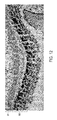
- FIG. 12 shows von Kossa staining of dentin-pulp stem cells on a synthetic-tubular-gelatin matrix after being subcutaneously implanted into nude mice for four weeks.
- FIG. 1A is a scanning electron microscope (“SEM”) image of human dentin 10 .
- the human dentin 10 includes a matrix 12 formed from a plurality of collagen fibers 14 .
- the matrix 12 also includes a plurality of pores or tubules 16 formed through the matrix 12 .
- FIG. 1B is an SEM image of a synthetic-tubular-gelatin matrix 100 , which is a biomimetic matrix approximating the human dentin 10 .
- the synthetic-tubular-gelatin matrix 100 comprises a matrix 102 formed from a plurality of gelatin nanofibers 104 (best seen in FIG. 1C ).
- the gelatin nanofibers 104 mimic the collagen fibers 14 (the same range of size and almost the same chemical composition) of the human dentin 10 .
- a plurality of tubules 106 are formed within the matrix 102 .
- the plurality of tubules 106 may be formed via laser ablation.
- the plurality of tubules 106 mimics the plurality of tubules 16 .
- the plurality of tubules 106 can be formed at various distances from one another and with various diameters depending on various design considerations.
- a diameter of one of the plurality of tubules 106 is approximately 2-3 ⁇ m, which is approximately the same diameter of the plurality of tubules 16 .
- the diameter of one of the plurality of tubules 106 ranges from 2-5 ⁇ m.
- FIG. 1C is a magnification of an SEM image showing one of the plurality of tubules 106 formed in the plurality of gelatin nanofibers 104 .
- FIG. 1D is a confocal image of the synthetic-tubular-gelatin matrix 100 , which shows a top view 108 , a side view 110 , and a side view 112 of the synthetic-tubular-gelatin matrix 100 .
- the side view 110 shows that plurality of tubules 106 pass completely through the synthetic-tubular-gelatin matrix 100 and that diameters of the plurality of tubules 106 changes along a length of the plurality of tubules 106 (similar to that of plurality of tubules 16 from a near-pulp region to a dental-enamel junction “DEJ” region).
- FIGS. 2A-2F control of a density of the plurality of tubules 106 and of a diameter of the plurality of tubules 106 is shown.
- FIGS. 2A-2C demonstrate that a tubular density—i.e., the number of tubules 106 per area—can be controlled.
- FIG. 2A depicts a relatively dense formation of tubules 106
- FIG. 2C depicts a relatively less dense formation of tubules 106
- FIG. 2B depicts a density of tubules 106 between the densities shown in FIGS. 2A and 2C .
- the density of the tubules 106 may be varied in accordance with various design parameters.
- the diameters of the tubules 106 may also be controlled as shown in FIGS. 2D-2F .
- the diameter of the tubules 106 may be varied between, for example, 300 nm and 30 ⁇ m.
- the diameter of the tubules 106 may be varied in accordance with various design parameters. In one embodiment, diameter variation is accomplished by manipulating, for example, an amount of time the laser is focused on the matrix 100 , an amount of energy supplied to the matrix 100 by the laser, and the like.
- FIGS. 3A and 3B show SEM images of the human dentin 10 and the synthetic-tubular-gelatin matrix 100 , respectively.
- the synthetic-tubular-gelatin matrix 100 mimics tubule diameter size, tubule gradient (i.e., a tapering of the tubule along its length, which results in a frustoconical shape), and tubule density.
- FIGS. 4A and 4B show SEM images of the synthetic-tubular-gelatin matrix 100 before and after mineralization, respectively. As shown in FIG. 4B , the plurality of gelatin nanofibers have become mineralized nanofibers 105 . The process of adding mineral to matrix is referred to as “mineralization.”
- FIG. 5A shows a dental pulp stem cell (“DPSC”) 202 cultured on a synthetic-gelatin matrix 200 .
- the synthetic-gelatin matrix 200 differs from the synthetic-tubular-gelatin matrix 100 in that it does not include a plurality of tubules.
- FIG. 5B shows a DPSC 114 cultured on the synthetic-tubular-gelatin matrix 100 . It is shown that a portion 116 of the DPSC 114 has descended into the tubule 106 . As compared to DPSC 202 , the DPSC 114 has obtained a superior attachment to the matrix.
- FIGS. 5C, 5D and 5E are confocal images of the synthetic-tubular-gelatin matrix 100 of FIG. 5B .
- the lighter portion of the image in FIG. 5C depicts the DPSC 114 .
- FIG. 5C shows a top view 118
- FIG. 5E shows a side view 120
- FIG. 5D shows a side view 122 of the synthetic-tubular-gelatin matrix 100 .
- the portion 116 of the DPSC 114 has descended into the tubule 106 to form a secure attachment to the synthetic-tubular-gelatin matrix 100 .
- FIG. 6A is a cross-sectional view of DPSCs 324 cultured on a synthetic-tubular-gelatin matrix 300 .
- FIG. 6B is an enhanced view of FIG. 6A , where the synthetic-tubular gelatin matrix 300 has been highlighted to better show a matrix 302 and tubules 306 , and the DBSCs 324 have been highlighted to better show F-actins 326 (shown as light gray layers stacked on top of the synthetic-tubular-gelatin matrix 300 ) and nuclei 328 (shown as bright spots within the light gray layers).
- FIG. 6C is a cross-sectional view of DPSCs 352 cultured on a synthetic-gelatin matrix 350 .
- FIG. 6D is an enhanced view of FIG. 6C , where the synthetic-gelatin matrix 350 has been highlighted to better show the matrix 350 , and the DPSCs 352 have been highlighted to better show F-actins 356 (shown as light gray layers stacked on top of the synthetic-tubular-gelatin matrix 350 ) and nuclei 358 (shown as bright spots within the light gray layers).
- FIGS. 6A and 6B show a significant increase in DPSC 324 growth and a significant improvement in the interface between the DPSCs 324 and the synthetic-tubular-gelatin matrix as compared to the DPSCs 352 shown in FIGS. 6C and 6D .
- FIG. 7A is a side view showing regenerated DPSCs 424 on a synthetic-tubular-gelatin matrix 400 after in-vitro culture for two weeks.
- FIG. 7B is a magnification of the image of FIG. 7A .
- F-actins 426 can be identified by the lighter gray colors of the image and nuclei 428 can be identified by the darker spots of the image.
- FIG. 7C is a side view showing regenerated DPSCs 452 on a synthetic-gelatin matrix 450 after in-vitro culture for two weeks.
- FIG. 7D is a magnification of the image of FIG. 7C .
- F-actins 456 can be identified by the lighter gray colors of the image and nuclei 458 can be identified by the darker spots of the image.
- FIGS. 7A and 7B show a significant increase in DPSC 424 growth and a significant improvement in the interface between the DPSCs 424 and the synthetic-tubular-gelatin matrix as compared to the DPSCs 452 shown in FIGS. 7C and 7D .
- FIG. 8A is an SEM image of DPSCs 524 cultured in vitro for two weeks on a synthetic-tubular-gelatin matrix 500 .
- FIG. 8B is an SEM image of DPSCs 552 cultured in vitro for two weeks on a synthetic-gelatin matrix 550 .
- FIG. 8A shows an improved interface between the DPSCs 524 and the synthetic-tubular-gelatin matrix 500 as compared to an interface between the DPSCs 552 and the synthetic-gelatin matrix 550 .
- FIG. 9A shows regenerated DPSCs 624 after in-vivo culturing for four weeks on a synthetic-tubular-gelatin matrix 600 .
- FIG. 9B is a magnification of the image in FIG. 9A .
- FIG. 9C shows regenerated DPSCs 552 after in-vivo culturing for four weeks on a synthetic-tubular-gelatin matrix 650 .
- FIG. 9D is a magnification of the image in FIG. 9C .
- FIG. 10A is an SEM image showing regenerated DPSCs 724 after in-vivo culturing for four weeks on a synthetic-tubular-gelatin matrix 700 .
- FIG. 10B is an SEM image showing regenerated DPSCs 752 after in-vivo culturing for four weeks on a synthetic-gelatin matrix 750 .
- FIG. 11 shows Haemotoxylin and Eosin (“H&E”) staining of DPSCs 824 and a synthetic-tubular-gelatin matrix 800 after being subcutaneously implanted into nude mice for four weeks.
- a tubular dentin tissue was successfully regenerated, and odontoblasts were aligned in a well-organized way along the tubular matrix, similar to that of natural tubular dentin.
- FIG. 12 shows von Kossa staining of DPSCs 924 and a synthetic-tubular-gelatin matrix 900 after being subcutaneously implanted into nude mice for four weeks. A mineralized tubular dentin tissue was clearly observed from the von Kossa staining.
- Nanofibrous synthetic matrix is fabricated by an electrospinning process using a high-voltage power supplier (Model: ES30P-SW, Gamma High Voltage Research Inc.). The diameter of the matrix nanofiber was tailored by the polymer concentration and electrospinning speed.
- a Leica Laser Microdissection 7000 (Leica microsystem, Germany) will be used to generate tubular structure on the nanofibrous matrix. The matrix will be tiled flat onto a glass coverslip.
- a software Leica laser microdissection V7.4.1 was used to design the pore distribution pattern. During the laser ablation process, the pore size was controlled by the laser aperture and laser pulse energy, and the pore density was modulated by the laser frequency and speed.
- the operation parameters of the equipment are as follows: laser aperture 30 Hz, laser pulse energy 30 Hz, laser speed 40 Hz, and laser pulse frequency 37 Hz. Using these parameters, more than 130000 tubular pores were created in each hour.
- the pulse frequency increased the number of pores generated in each unit time. Because the laser strength is the highest on the top surface of the matrix and the lowest on the bottom of the matrix, an inverted cone-like structure of each cylindrical pore will be created during the laser ablation process.
- One advantage of using this technology is its capability to precisely relocate to its previous position; therefore, the ablation process can be repeated multiple times to ensure that each pore in the matrix is open.
- the operation parameters will be modulated in the following ranges: laser aperture 20-45, laser pulse energy 15-35, laser speed 5-100, and laser pulse frequency 10-65 Hz.
- the new technology has been developed and the biomimetic synthetic matrix has been prepared and optimized.
- the pore size is larger on the top surface of the matrix relative to the bottom surface and progressively decreases in size along the depth of the matrix.
- the bottom surface of the matrix is contacted with a glass substrate prior to exposing the top surface of the matrix to the laser. Contacting the bottom surface of the matrix with a glass substrate causes more heat to be generated on the bottom of the matrix than on the top surface, which in turn generates larger pores on the bottom of the matrix relative to the top surface of the matrix.
Landscapes
- Engineering & Computer Science (AREA)
- Health & Medical Sciences (AREA)
- Mechanical Engineering (AREA)
- Textile Engineering (AREA)
- Life Sciences & Earth Sciences (AREA)
- Chemical & Material Sciences (AREA)
- Epidemiology (AREA)
- Public Health (AREA)
- Veterinary Medicine (AREA)
- Oral & Maxillofacial Surgery (AREA)
- Orthopedic Medicine & Surgery (AREA)
- Dentistry (AREA)
- General Health & Medical Sciences (AREA)
- Animal Behavior & Ethology (AREA)
- Dispersion Chemistry (AREA)
- Biomedical Technology (AREA)
- Developmental Biology & Embryology (AREA)
- Physics & Mathematics (AREA)
- Optics & Photonics (AREA)
- Ceramic Engineering (AREA)
- Chemical Kinetics & Catalysis (AREA)
- General Chemical & Material Sciences (AREA)
- Oil, Petroleum & Natural Gas (AREA)
- Plasma & Fusion (AREA)
- Materials For Medical Uses (AREA)
- Micro-Organisms Or Cultivation Processes Thereof (AREA)
Abstract
Description
Claims (6)
Priority Applications (1)
| Application Number | Priority Date | Filing Date | Title |
|---|---|---|---|
| US14/881,922 US9913700B2 (en) | 2014-10-13 | 2015-10-13 | Method of producing a polymer matrix |
Applications Claiming Priority (2)
| Application Number | Priority Date | Filing Date | Title |
|---|---|---|---|
| US201462063334P | 2014-10-13 | 2014-10-13 | |
| US14/881,922 US9913700B2 (en) | 2014-10-13 | 2015-10-13 | Method of producing a polymer matrix |
Publications (2)
| Publication Number | Publication Date |
|---|---|
| US20160184058A1 US20160184058A1 (en) | 2016-06-30 |
| US9913700B2 true US9913700B2 (en) | 2018-03-13 |
Family
ID=56162928
Family Applications (1)
| Application Number | Title | Priority Date | Filing Date |
|---|---|---|---|
| US14/881,922 Active US9913700B2 (en) | 2014-10-13 | 2015-10-13 | Method of producing a polymer matrix |
Country Status (1)
| Country | Link |
|---|---|
| US (1) | US9913700B2 (en) |
Families Citing this family (1)
| Publication number | Priority date | Publication date | Assignee | Title |
|---|---|---|---|---|
| NL2020124B1 (en) * | 2017-12-19 | 2019-06-26 | Innovative Mechanical Engineering Tech B V | Electrospinning device and method |
Citations (2)
| Publication number | Priority date | Publication date | Assignee | Title |
|---|---|---|---|---|
| US20060019389A1 (en) * | 2004-07-22 | 2006-01-26 | Avner Yayon | Porous plasma protein matrices and methods for preparation thereof |
| US20090074832A1 (en) * | 2005-04-04 | 2009-03-19 | Technion Research & Development Foundation Ltd. | Medical Scaffold, Methods of Fabrication and Using Thereof |
-
2015
- 2015-10-13 US US14/881,922 patent/US9913700B2/en active Active
Patent Citations (2)
| Publication number | Priority date | Publication date | Assignee | Title |
|---|---|---|---|---|
| US20060019389A1 (en) * | 2004-07-22 | 2006-01-26 | Avner Yayon | Porous plasma protein matrices and methods for preparation thereof |
| US20090074832A1 (en) * | 2005-04-04 | 2009-03-19 | Technion Research & Development Foundation Ltd. | Medical Scaffold, Methods of Fabrication and Using Thereof |
Also Published As
| Publication number | Publication date |
|---|---|
| US20160184058A1 (en) | 2016-06-30 |
Similar Documents
| Publication | Publication Date | Title |
|---|---|---|
| Xing et al. | Engineering complex anisotropic scaffolds beyond simply uniaxial alignment for tissue engineering | |
| Su et al. | 3D electrospun synthetic extracellular matrix for tissue regeneration | |
| Kong et al. | Biomechanical microenvironment in peripheral nerve regeneration: from pathophysiological understanding to tissue engineering development | |
| US12144716B2 (en) | Biomedical patches with aligned fibers | |
| Deng et al. | Micro/nanometer‐structured scaffolds for regeneration of both cartilage and subchondral bone | |
| DE10312144B4 (en) | Carrier material for tissue and cell culture and the production of implant materials | |
| Zhou et al. | Perspectives on the novel multifunctional nerve guidance conduits: from specific regenerative procedures to motor function rebuilding | |
| Zheng et al. | Advances in nerve guidance conduits for peripheral nerve repair and regeneration | |
| Seil et al. | Electrically active nanomaterials as improved neural tissue regeneration scaffolds | |
| Sankar et al. | Electrospun nanofibres to mimic natural hierarchical structure of tissues: application in musculoskeletal regeneration | |
| CN105688274B (en) | A kind of preparation process of polycaprolactone/gelatin electrospinning compound rest | |
| Mangano et al. | In vivo behavior of a custom-made 3D synthetic bone substitute in sinus augmentation procedures in sheep | |
| Laijun et al. | An enhanced periosteum structure/function dual mimicking membrane for in-situ restorations of periosteum and bone | |
| Oprea et al. | Electrospun nanofibers for tissue engineering applications | |
| Wang et al. | Geometric anisotropy on biomaterials surface for vascular scaffold design: engineering and biological advances | |
| WO2021087281A1 (en) | 3d-bioprinted scaffolds for tissue regeneration | |
| Ma et al. | Hierarchically structured biomaterials for tissue regeneration | |
| US9913700B2 (en) | Method of producing a polymer matrix | |
| US9974883B2 (en) | Method and apparatus to control the heterogeneous flow of bone cement and improve osseointegration of cemented implant | |
| JP7034523B2 (en) | Difference Tissue Engineering Nerves and Applications | |
| CN109248343A (en) | A kind of self assembly polypeptide hydrogel bracket and preparation method thereof | |
| US20230086561A1 (en) | Implantable guide element and methods of fabrication and use thereof | |
| Zheng et al. | Fabrication and surface characterization of titanium dioxide nanotubes on titanium implants | |
| CN118141565A (en) | Porous bionic Achilles tendon scaffold and preparation method thereof | |
| JP2024535441A (en) | Cellularized nerve regeneration graft and method for producing same |
Legal Events
| Date | Code | Title | Description |
|---|---|---|---|
| AS | Assignment |
Owner name: THE TEXAS A&M UNIVERSITY SYSTEM, TEXAS Free format text: ASSIGNMENT OF ASSIGNORS INTEREST;ASSIGNORS:LIU, XIAOHUA;MA, CHI;QU, TIEJUN;REEL/FRAME:036913/0548 Effective date: 20151023 |
|
| AS | Assignment |
Owner name: NATIONAL INSTITUTES OF HEALTH (NIH), U.S. DEPT. OF Free format text: CONFIRMATORY LICENSE;ASSIGNOR:TEXAS A&M UNIVERSITY;REEL/FRAME:045013/0287 Effective date: 20180102 |
|
| STCF | Information on status: patent grant |
Free format text: PATENTED CASE |
|
| MAFP | Maintenance fee payment |
Free format text: PAYMENT OF MAINTENANCE FEE, 4TH YR, SMALL ENTITY (ORIGINAL EVENT CODE: M2551); ENTITY STATUS OF PATENT OWNER: SMALL ENTITY Year of fee payment: 4 |
|
| MAFP | Maintenance fee payment |
Free format text: PAYMENT OF MAINTENANCE FEE, 8TH YR, SMALL ENTITY (ORIGINAL EVENT CODE: M2552); ENTITY STATUS OF PATENT OWNER: SMALL ENTITY Year of fee payment: 8 |