US9909309B1 - Glass anchoring system - Google Patents
Glass anchoring system Download PDFInfo
- Publication number
- US9909309B1 US9909309B1 US15/401,179 US201715401179A US9909309B1 US 9909309 B1 US9909309 B1 US 9909309B1 US 201715401179 A US201715401179 A US 201715401179A US 9909309 B1 US9909309 B1 US 9909309B1
- Authority
- US
- United States
- Prior art keywords
- blocks
- glass
- connecting bar
- panels
- pane
- Prior art date
- Legal status (The legal status is an assumption and is not a legal conclusion. Google has not performed a legal analysis and makes no representation as to the accuracy of the status listed.)
- Active
Links
Images


Classifications
-
- E—FIXED CONSTRUCTIONS
- E04—BUILDING
- E04B—GENERAL BUILDING CONSTRUCTIONS; WALLS, e.g. PARTITIONS; ROOFS; FLOORS; CEILINGS; INSULATION OR OTHER PROTECTION OF BUILDINGS
- E04B5/00—Floors; Floor construction with regard to insulation; Connections specially adapted therefor
- E04B5/46—Special adaptation of floors for transmission of light, e.g. by inserts of glass
-
- B—PERFORMING OPERATIONS; TRANSPORTING
- B32—LAYERED PRODUCTS
- B32B—LAYERED PRODUCTS, i.e. PRODUCTS BUILT-UP OF STRATA OF FLAT OR NON-FLAT, e.g. CELLULAR OR HONEYCOMB, FORM
- B32B17/00—Layered products essentially comprising sheet glass, or glass, slag, or like fibres
- B32B17/06—Layered products essentially comprising sheet glass, or glass, slag, or like fibres comprising glass as the main or only constituent of a layer, next to another layer of a specific material
- B32B17/10—Layered products essentially comprising sheet glass, or glass, slag, or like fibres comprising glass as the main or only constituent of a layer, next to another layer of a specific material of synthetic resin
- B32B17/10005—Layered products essentially comprising sheet glass, or glass, slag, or like fibres comprising glass as the main or only constituent of a layer, next to another layer of a specific material of synthetic resin laminated safety glass or glazing
- B32B17/10009—Layered products essentially comprising sheet glass, or glass, slag, or like fibres comprising glass as the main or only constituent of a layer, next to another layer of a specific material of synthetic resin laminated safety glass or glazing characterized by the number, the constitution or treatment of glass sheets
- B32B17/10036—Layered products essentially comprising sheet glass, or glass, slag, or like fibres comprising glass as the main or only constituent of a layer, next to another layer of a specific material of synthetic resin laminated safety glass or glazing characterized by the number, the constitution or treatment of glass sheets comprising two outer glass sheets
- B32B17/10045—Layered products essentially comprising sheet glass, or glass, slag, or like fibres comprising glass as the main or only constituent of a layer, next to another layer of a specific material of synthetic resin laminated safety glass or glazing characterized by the number, the constitution or treatment of glass sheets comprising two outer glass sheets with at least one intermediate layer consisting of a glass sheet
-
- B—PERFORMING OPERATIONS; TRANSPORTING
- B32—LAYERED PRODUCTS
- B32B—LAYERED PRODUCTS, i.e. PRODUCTS BUILT-UP OF STRATA OF FLAT OR NON-FLAT, e.g. CELLULAR OR HONEYCOMB, FORM
- B32B17/00—Layered products essentially comprising sheet glass, or glass, slag, or like fibres
- B32B17/06—Layered products essentially comprising sheet glass, or glass, slag, or like fibres comprising glass as the main or only constituent of a layer, next to another layer of a specific material
- B32B17/10—Layered products essentially comprising sheet glass, or glass, slag, or like fibres comprising glass as the main or only constituent of a layer, next to another layer of a specific material of synthetic resin
- B32B17/10005—Layered products essentially comprising sheet glass, or glass, slag, or like fibres comprising glass as the main or only constituent of a layer, next to another layer of a specific material of synthetic resin laminated safety glass or glazing
- B32B17/10165—Functional features of the laminated safety glass or glazing
- B32B17/10293—Edge features, e.g. inserts or holes
-
- B—PERFORMING OPERATIONS; TRANSPORTING
- B32—LAYERED PRODUCTS
- B32B—LAYERED PRODUCTS, i.e. PRODUCTS BUILT-UP OF STRATA OF FLAT OR NON-FLAT, e.g. CELLULAR OR HONEYCOMB, FORM
- B32B17/00—Layered products essentially comprising sheet glass, or glass, slag, or like fibres
- B32B17/06—Layered products essentially comprising sheet glass, or glass, slag, or like fibres comprising glass as the main or only constituent of a layer, next to another layer of a specific material
- B32B17/10—Layered products essentially comprising sheet glass, or glass, slag, or like fibres comprising glass as the main or only constituent of a layer, next to another layer of a specific material of synthetic resin
- B32B17/10005—Layered products essentially comprising sheet glass, or glass, slag, or like fibres comprising glass as the main or only constituent of a layer, next to another layer of a specific material of synthetic resin laminated safety glass or glazing
- B32B17/1055—Layered products essentially comprising sheet glass, or glass, slag, or like fibres comprising glass as the main or only constituent of a layer, next to another layer of a specific material of synthetic resin laminated safety glass or glazing characterized by the resin layer, i.e. interlayer
- B32B17/10761—Layered products essentially comprising sheet glass, or glass, slag, or like fibres comprising glass as the main or only constituent of a layer, next to another layer of a specific material of synthetic resin laminated safety glass or glazing characterized by the resin layer, i.e. interlayer containing vinyl acetal
-
- C—CHEMISTRY; METALLURGY
- C03—GLASS; MINERAL OR SLAG WOOL
- C03C—CHEMICAL COMPOSITION OF GLASSES, GLAZES OR VITREOUS ENAMELS; SURFACE TREATMENT OF GLASS; SURFACE TREATMENT OF FIBRES OR FILAMENTS MADE FROM GLASS, MINERALS OR SLAGS; JOINING GLASS TO GLASS OR OTHER MATERIALS
- C03C27/00—Joining pieces of glass to pieces of other inorganic material; Joining glass to glass other than by fusing
- C03C27/06—Joining glass to glass by processes other than fusing
- C03C27/10—Joining glass to glass by processes other than fusing with the aid of adhesive specially adapted for that purpose
-
- E—FIXED CONSTRUCTIONS
- E04—BUILDING
- E04B—GENERAL BUILDING CONSTRUCTIONS; WALLS, e.g. PARTITIONS; ROOFS; FLOORS; CEILINGS; INSULATION OR OTHER PROTECTION OF BUILDINGS
- E04B1/00—Constructions in general; Structures which are not restricted either to walls, e.g. partitions, or floors or ceilings or roofs
- E04B1/003—Balconies; Decks
-
- E—FIXED CONSTRUCTIONS
- E04—BUILDING
- E04B—GENERAL BUILDING CONSTRUCTIONS; WALLS, e.g. PARTITIONS; ROOFS; FLOORS; CEILINGS; INSULATION OR OTHER PROTECTION OF BUILDINGS
- E04B1/00—Constructions in general; Structures which are not restricted either to walls, e.g. partitions, or floors or ceilings or roofs
- E04B1/18—Structures comprising elongated load-supporting parts, e.g. columns, girders, skeletons
-
- E—FIXED CONSTRUCTIONS
- E04—BUILDING
- E04B—GENERAL BUILDING CONSTRUCTIONS; WALLS, e.g. PARTITIONS; ROOFS; FLOORS; CEILINGS; INSULATION OR OTHER PROTECTION OF BUILDINGS
- E04B5/00—Floors; Floor construction with regard to insulation; Connections specially adapted therefor
- E04B5/02—Load-carrying floor structures formed substantially of prefabricated units
- E04B5/023—Separate connecting devices for prefabricated floor-slabs
-
- E—FIXED CONSTRUCTIONS
- E04—BUILDING
- E04C—STRUCTURAL ELEMENTS; BUILDING MATERIALS
- E04C1/00—Building elements of block or other shape for the construction of parts of buildings
- E04C1/42—Building elements of block or other shape for the construction of parts of buildings of glass or other transparent material
-
- E—FIXED CONSTRUCTIONS
- E04—BUILDING
- E04F—FINISHING WORK ON BUILDINGS, e.g. STAIRS, FLOORS
- E04F15/00—Flooring
- E04F15/02—Flooring or floor layers composed of a number of similar elements
- E04F15/02005—Construction of joints, e.g. dividing strips
- E04F15/02011—Construction of joints, e.g. dividing strips with joint fillings integrated in the flooring elements
-
- E—FIXED CONSTRUCTIONS
- E04—BUILDING
- E04F—FINISHING WORK ON BUILDINGS, e.g. STAIRS, FLOORS
- E04F15/00—Flooring
- E04F15/02—Flooring or floor layers composed of a number of similar elements
- E04F15/02005—Construction of joints, e.g. dividing strips
- E04F15/02016—Construction of joints, e.g. dividing strips with sealing elements between flooring elements
-
- E—FIXED CONSTRUCTIONS
- E04—BUILDING
- E04F—FINISHING WORK ON BUILDINGS, e.g. STAIRS, FLOORS
- E04F15/00—Flooring
- E04F15/02—Flooring or floor layers composed of a number of similar elements
- E04F15/02044—Separate elements for fastening to an underlayer
-
- E—FIXED CONSTRUCTIONS
- E04—BUILDING
- E04F—FINISHING WORK ON BUILDINGS, e.g. STAIRS, FLOORS
- E04F15/00—Flooring
- E04F15/02—Flooring or floor layers composed of a number of similar elements
- E04F15/02177—Floor elements for use at a specific location
- E04F15/02183—Floor elements for use at a specific location for outdoor use, e.g. in decks, patios, terraces, verandas or the like
-
- E—FIXED CONSTRUCTIONS
- E04—BUILDING
- E04F—FINISHING WORK ON BUILDINGS, e.g. STAIRS, FLOORS
- E04F15/00—Flooring
- E04F15/02—Flooring or floor layers composed of a number of similar elements
- E04F15/08—Flooring or floor layers composed of a number of similar elements only of stone or stone-like material, e.g. ceramics, concrete; of glass or with a top layer of stone or stone-like material, e.g. ceramics, concrete or glass
- E04F15/082—Flooring or floor layers composed of a number of similar elements only of stone or stone-like material, e.g. ceramics, concrete; of glass or with a top layer of stone or stone-like material, e.g. ceramics, concrete or glass with a top layer of stone or stone-like material, e.g. ceramics, concrete or glass in combination with a lower layer of other material
-
- E—FIXED CONSTRUCTIONS
- E04—BUILDING
- E04F—FINISHING WORK ON BUILDINGS, e.g. STAIRS, FLOORS
- E04F15/00—Flooring
- E04F15/02—Flooring or floor layers composed of a number of similar elements
- E04F15/10—Flooring or floor layers composed of a number of similar elements of other materials, e.g. fibrous or chipped materials, organic plastics, magnesite tiles, hardboard, or with a top layer of other materials
- E04F15/107—Flooring or floor layers composed of a number of similar elements of other materials, e.g. fibrous or chipped materials, organic plastics, magnesite tiles, hardboard, or with a top layer of other materials composed of several layers, e.g. sandwich panels
-
- E—FIXED CONSTRUCTIONS
- E04—BUILDING
- E04F—FINISHING WORK ON BUILDINGS, e.g. STAIRS, FLOORS
- E04F15/00—Flooring
- E04F15/02—Flooring or floor layers composed of a number of similar elements
- E04F15/02044—Separate elements for fastening to an underlayer
- E04F2015/02105—Separate elements for fastening to an underlayer without load-supporting elongated furring elements between the flooring elements and the underlayer
- E04F2015/02111—Separate elements for fastening to an underlayer without load-supporting elongated furring elements between the flooring elements and the underlayer not adjustable
- E04F2015/02122—Separate elements for fastening to an underlayer without load-supporting elongated furring elements between the flooring elements and the underlayer not adjustable with fastening elements engaging holes or grooves in the side faces of the flooring elements
Landscapes
- Engineering & Computer Science (AREA)
- Architecture (AREA)
- Civil Engineering (AREA)
- Structural Engineering (AREA)
- Chemical & Material Sciences (AREA)
- Physics & Mathematics (AREA)
- Electromagnetism (AREA)
- Ceramic Engineering (AREA)
- Life Sciences & Earth Sciences (AREA)
- Chemical Kinetics & Catalysis (AREA)
- General Chemical & Material Sciences (AREA)
- Geochemistry & Mineralogy (AREA)
- Materials Engineering (AREA)
- Organic Chemistry (AREA)
- Load-Bearing And Curtain Walls (AREA)
Abstract
A glass anchoring system, for securing a pair of adjacent panels of structural glass to a mid support beam and creating a walkable glass. Each panel has a fastening edge and has an upper pane, a middle pane, and a lower pane. The middle pane has a cutout along the fastening edge. A pair of blocks fit within the cutouts and are laminated within the panels. When the panels are positioned upon the mid support beam, the blocks face each other across a gap between the adjacent panels. A connecting bar extends across the gap and into both of the blocks. A bolt extends in the gap, downwardly through the connecting bar, and tightens against the connecting bar as it secures to the mid support beam.
Description
The present disclosure relates generally to a glass anchoring. More particularly, the present disclosure relates to a system for securing multi-panel glass assemblies in a decking application against upward forces.
Structural glass panels being used as a walkable surface is a relatively new and unexplored application. The nature of glass as a building material presents new challenges to architects and structural engineers, and thus requires the development of new systems and concepts to overcome these challenges.
Among the challenges of using structural glass is the difficulty of fastening panels. Many conventional fastening systems cannot be used with structural glass. In addition, one of the sought after features of glass as a building material is it's transparency and seamless appearance. Most conventional fasteners will either spoil this seamless appearance or reveal their unsightly nature since the nature of the glass would be to reveal that which is ordinarily concealed by opaque building materials.
One such challenge is using structural glass as a walkable surface for outdoor structures such as balconies, decks, and other cantilevered platforms. Since structural glass is quite heavy, for many indoor structures, the weight of the glass itself can be sufficient to ensure it will remain in place on a horizontal surface. However, for outdoor installations, wind becomes a factor. In particular, when strong winds blow under such structures, the weight of the glass alone may be insufficient to withstand upward forces exerted upon the glass panels. Direct fastening of the glass is necessary to prevent the glass panels from lifting when subjected to heavy winds.
Various fastening systems have been proposed and are available for securing a variety of building materials. While these units may be suitable for the particular purpose employed, or for general use, they would not be as suitable for the purposes of the present disclosure as disclosed hereafter.
In the present disclosure, where a document, act or item of knowledge is referred to or discussed, this reference or discussion is not an admission that the document, act or item of knowledge or any combination thereof was at the priority date, publicly available, known to the public, part of common general knowledge or otherwise constitutes prior art under the applicable statutory provisions; or is known to be relevant to an attempt to solve any problem with which the present disclosure is concerned.
While certain aspects of conventional technologies have been discussed to facilitate the present disclosure, no technical aspects are disclaimed and it is contemplated that the claims may encompass one or more of the conventional technical aspects discussed herein.
An aspect of an example embodiment in the present disclosure is to provide a system that facilitates the use of structural glass in providing a walkable surface. Accordingly, the present disclosure provides an anchoring system for securing structural glass to supporting framework.
It is another aspect of an example embodiment in the present disclosure to allow large walkable surfaces to be created with multiple panels of structural glass. Accordingly, this anchoring system provides an effective solution for mid-span securing of adjacent glass panels.
It is yet another aspect of an example embodiment in the present disclosure to allow structural glass panels to be used in outdoor decking, while safeguarding against upward drafts from hurricane force winds. Accordingly, the anchoring system is configured to hold the panels securely in place when significant upward forces are exerted against the lowermost pane of each of the panels.
It is a still further aspect of an example embodiment to provide an anchoring system that has superior strength, while providing a nearly seamless, unobstructed appearance. Accordingly, the system employs blocks that are laminated into a middle pane of a multiple pane panel along their fastening edges. A fastener extends in a gap between the fastening edges of adjacent panes, connects the blocks of the adjacent panes, and secures them to a mid support beam upon which the panels rest.
Accordingly, the present disclosure describes a glass anchoring system, for securing a pair of adjacent panels of structural glass to a mid support beam and creating a walkable glass. Each panel has a fastening edge and has an upper pane, a middle pane, and a lower pane. The middle pane has a cutout along the fastening edge. A pair of blocks fit within the cutouts and are laminated within the panels. When the panels are positioned upon the mid support beam, the blocks face each other across a gap between the adjacent panels. A connecting bar extends across the gap and into both of the blocks. A bolt extends in the gap, downwardly through the connecting bar, and tightens against the connecting bar as it secures to the mid support beam.
The present disclosure addresses at least one of the foregoing disadvantages. However, it is contemplated that the present disclosure may prove useful in addressing other problems and deficiencies in a number of technical areas. Therefore, the claims should not necessarily be construed as limited to addressing any of the particular problems or deficiencies discussed hereinabove. To the accomplishment of the above, this disclosure may be embodied in the form illustrated in the accompanying drawings. Attention is called to the fact, however, that the drawings are illustrative only. Variations are contemplated as being part of the disclosure.
In the drawings, like elements are depicted by like reference numerals. The drawings are briefly described as follows.
The present disclosure now will be described more fully hereinafter with reference to the accompanying drawings, which show various example embodiments. However, the present disclosure may be embodied in many different forms and should not be construed as limited to the example embodiments set forth herein. Rather, these example embodiments are provided so that the present disclosure is thorough, complete and fully conveys the scope of the present disclosure to those skilled in the art.
Each panel has at least two panes 31 of heavy structural glass, namely a lowermost pane 31L, an uppermost pane 31U, and a middle pane 31M. The panels 30 and its panes 31 each have a fastening edge 32. The fastening edges 32 of the adjacent panels 30 and its panes face each other across a gap 200 between the panels 30. The panels 30 are secured together with a fastener 40 that includes a pair of blocks 50, a connecting bar 60 that extends into the blocks 50 and across the gap 200, and a bolt 65. The bolt 65 extends through the connecting bar 60, vertically through the gap 200, and secures the connecting bar 60 to the mid support beam 100.
Referring now to FIG. 6B , the block 50 is located within the cutout 33 of the middle pane 31M. The inside surface 51 is coextensive with the fastening edge 32, and the top surface 50T and bottom surface 50T are flush with the middle pane 31M. Now, with the block 50 in position within the cutout 33 of the middle pane 31M, the panes 31L, 31M, and 31U can be laminated to create the panel 30. The panel 30 is laminated using conventional laminating technology wherein the panes 31L, 31M, and 31U are bonded together, except in this case the block 50 is formed into the panel 30 during the lamination process. In particular, interlayer sheets are interposed between the panes 31 to bond to the glass surfaces using heat and pressure. The interlayer sheets are typically made of PVB (polyvinyl butyral), but any bonding material suitable for laminating structural glass may be used. As illustrated, a first interlayer sheet 71 extends between the uppermost pane 31U and a middle pane 31M and is bonded to the top surface 50T of the block 50. In addition, a second interlayer sheet 72 extends between the middle pane 31M and the lowermost pane 31L and is bonded to the bottom surface 50 of the block. Note that since the interlayer sheets 71, 72 are so thin, especially in proportion to panes 31L, 31M, 31U, they have been omitted in all other drawing figures for clarity. When the uppermost pane 31U, middle pane 31M, and lower pane 31L are laminated together, the block 50 is held securely and permanently within the panel 30, with the inside surface 51 coextensive with the fastening edge 32 as seen in FIG. 7 . Referring to FIG. 7 , with the block 50 bonded within the panel 30, the panel 30 is ready for installation. This lamination process is performed for two or more panels 30 that are to be positioned adjacent to each other, with their fastening edges 32 facing each other and separated by the gap 200, as seen in FIG. 8 .
With their associated panels 30 omitted for clarity, the relationship between the connecting bar 60 and blocks 50 is illustrated in FIGS. 5A, 5B, and 5C . In particular, the blocks 50 are shown spaced apart by a distance equivalent to the gap 200 between panels 30 in an actual installation as seen in FIG. 11 . Note that when the pair of blocks 50 oppose each other, the hollows 56 have complementary structure. That is, the first end 511, and it's corresponding shallow end 56S of the hollow 56 of one of the blocks 50 is directly across from the second end 512 of the other block 50 that it faces. The arcuate inside walls 56A of the blocks 50 substantially trace two quadrants of the same circle, a circle that is centered on the center 60C of the connecting bar 60 that extends between the blocks 50. Also of note, as seen in FIG. 5C the stop walls 56P of the facing blocks 50 are offset by a distance that is substantially the same as a transverse width 60W of the connecting bar 60. An initial relative position of the blocks 50 and connecting bar 60 are seen in FIG. 5A , wherein the connecting bar 60 extends substantially parallel to the inside surface 51 of the blocks 50. This position allows the connecting bar 60 to move vertically within the gap 200 so that it is vertically aligned with the hollows 56. Then, the connecting bar 60 is rotated clockwise into position, as seen in FIG. 5B , wherein the ends 60E sweep through the hollow 56, roughly following the arcuate inside walls 56A of the blocks 56. Finally, the connecting bar 60 reaches the position of FIG. 5C , where the connecting bar 60 extends against the stop wall 56P of the hollows 56 of both blocks 50, substantially parallel to said stop walls 56P and perpendicular to the inside surfaces 51. Note that in FIG. 5C , the connecting bar 5C is in the optimal position for anchoring the glass panels. Removing the fastener would require rotating the connecting bar 60 counterclockwise by ninety degrees, so that it once again extends parallel to the inside surface 51 as shown in FIG. 5A , such that it can be retrieved upwardly through the gap 200.
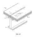
As illustrated in FIG. 9 , the bolt 65 has a fastening end 66 and a tightening end 68. The fastening end 66 may have a threaded portion 67, and the tightening end 68 may have an engagement head 69. In the embodiment illustrated, the fastening end 66 is configured to extend downwardly through a gasket bore 84 and into the mid support beam 80. In particular, in this embodiment, the mid support beam 80 has a threaded opening 104 in the top flange surface 101. Accordingly, during installation of this embodiment, the fastening end 66 of the bolt 65 is extended downwardly through the gap 200 between the blocks 50, through the gasket bore 84 of the glass setting gasket 80, and into the threaded opening 104 in the mid support beam 100. The tightening end 68 is then rotated clockwise until the threaded portion 67 of the fastening end 66 is secured within the threaded opening 104 of the mid support beam 100. Note that as the bolt 65 extends through the connecting bar 60, the bolt 65 generally slips within the connecting bar as the bolt 65 is rotated clockwise. When the bolt gets tight, however, and the tightening end 68 is nearly flush and tight against the connecting bar 60, as the bolt 65 is rotated in the clockwise direction, the tendency is for the connecting bar 60 to also rotate in the clockwise direction. Advantageously, any clockwise rotation of the connecting bar 60 only acts to ensure that it is properly positioned in the optimal anchoring position within the blocks 50, as indicated in FIG. 5C .
Referring again to FIG. 11 , with the bolt 65 secured to the mid support beam 100 and the connecting bar 60 held tightly in place when it extends into the blocks 50 of both of the adjacent panels 30, upward force upon the lowermost pane 31L will be exerted against the block 50, the connecting bar 60, the bolt 65, and thus borne by the mid support beam 100. With the panels 30 thereby secured to the beam 100, the installation may be completed by filling the gap above the bolt 65 with a sealant, such as a Dow Corning Structural Silicone.
It is understood that when an element is referred hereinabove as being “on” another element, it can be directly on the other element or intervening elements may be present therebetween. In contrast, when an element is referred to as being “directly on” another element, there are no intervening elements present.
Moreover, any components or materials can be formed from a same, structurally continuous piece or separately fabricated and connected.
It is further understood that, although ordinal terms, such as, “first,” “second,” “third,” are used herein to describe various elements, components, regions, layers and/or sections, these elements, components, regions, layers and/or sections should not be limited by these terms. These terms are only used to distinguish one element, component, region, layer or section from another element, component, region, layer or section. Thus, “a first element,” “component,” “region,” “layer” or “section” discussed below could be termed a second element, component, region, layer or section without departing from the teachings herein.
Spatially relative terms, such as “beneath,” “below,” “lower,” “above,” “upper” and the like, are used herein for ease of description to describe one element or feature's relationship to another element(s) or feature(s) as illustrated in the figures. It is understood that the spatially relative terms are intended to encompass different orientations of the device in use or operation in addition to the orientation depicted in the figures. For example, if the device in the figures is turned over, elements described as “below” or “beneath” other elements or features would then be oriented “above” the other elements or features. Thus, the example term “below” can encompass both an orientation of above and below. The device can be otherwise oriented (rotated 90 degrees or at other orientations) and the spatially relative descriptors used herein interpreted accordingly.
Example embodiments are described herein with reference to cross section illustrations that are schematic illustrations of idealized embodiments. As such, variations from the shapes of the illustrations as a result, for example, of manufacturing techniques and/or tolerances, are to be expected. Thus, example embodiments described herein should not be construed as limited to the particular shapes of regions as illustrated herein, but are to include deviations in shapes that result, for example, from manufacturing. For example, a region illustrated or described as flat may, typically, have rough and/or nonlinear features. Moreover, sharp angles that are illustrated may be rounded. Thus, the regions illustrated in the figures are schematic in nature and their shapes are not intended to illustrate the precise shape of a region and are not intended to limit the scope of the present claims.
In conclusion, herein is presented a glass anchoring system, for securing a pair of adjacent panels of structural glass. The disclosure is illustrated by example in the drawing figures, and throughout the written description. It should be understood that numerous variations are possible, while adhering to the inventive concept. Such variations are contemplated as being a part of the present disclosure.
Claims (13)
1. A glass anchoring system, for providing a horizontal and walkable glass decking surface, comprising:
a pair of adjacent structural glass panels, each structural glass panel having at least three panes of substantially the same size including an uppermost pane, a lowermost pane, and a middle pane, the structural glass panels each having a fastening edge, the panes of each glass panel also having fastening edges that are vertically aligned, the fastening edge of the two panels are next to and parallel to each other, separated by a gap, the middle pane of the glass panels each contain a cutout extending laterally from the gap into said panel;
a mid support beam, the pair of adjacent structural glass panels are supported by the mid support beam near their fastening edges such the gap extends over the beam; and
a fastening device that is secured to the beam, the fastening device includes a pair of blocks and extends upwardly through the gap, each of the blooks extend laterally beyond the fastening edge of one of the panels into the cutout of the middle pane of said one of the panels, such that upward force on the lowermost pane is exerted directly onto the fastening device.
2. The glass anchoring system as described in claim 1 , wherein the pair of blocks each having an inside wall having a first end and a second end, an end opening from near the first end to substantially midway toward the second end and a hollow that extends into said block, the hollow having a shallow end near the first end of the block and a deep end substantially midway between the first end and second end, the hollow having an arcuate inside wall between the shallow end and deep end and having a stop wall at the deep end that extends perpendicular to the inside surface; wherein the connecting bar extending against and parallel to the stop wall of both blocks, and wherein the blocks are adapted so that the connecting bar may be rotated counter clockwise with respect to a vertical axis to remove the connecting bar from the blocks.
3. The glass anchoring system as described in claim 2 , wherein the connecting bar has a pair of ends, the ends each extending within one of the blocks, and a center having a central bore; and further comprising a bolt, the bolt extending through the connecting bar and into the mid support beam for securing the connecting bar to the beam.
4. The glass anchoring system as described in claim 3 , wherein the blocks each have an outer wall, a top surface, and a bottom surface; wherein the top surface and the bottom surface are substantially flat; and wherein the middle pane of each panel has a thickness, the blocks have a height between the bottom surface and the top surface that is substantially the same as the thickness of the middle panel; wherein for each panel a first interlayer extends between the uppermost pane and a middle pane and is bonded to the top surface of the block, and a second interlayer extends between the middle pane and the lowermost pane and is bonded to the bottom surface of the block.
5. The glass anchoring system as described in claim 4 , wherein the blocks are each the shape of a half circle with the inside surface extending along a diameter of said half circle.
6. A glass anchoring system, for securing a pair of adjacent panels of structural glass upon a mid support beam, each panel having an uppermost pane, a lowermost pane, and a middle pane, the middle pane having a fastening edge and a cutout extending laterally into the middle pane from the fastening edge, the fastening edges of the middle panes of the adjacent panels parallel to each other and separated by a gap, comprising:
a connecting bar having a pair of ends and a center having a central bore through said center;
a pair of blocks adapted for extending in the cutout of one of the panels of glass, each block having an inside wall having a first end and a second end, an end opening from near the first end to substantially midway toward the second end and a hollow that extends into said block, the hollow having a shallow end near the first end of the block and a deep end substantially midway between the first end and second end, the hollow having an arcuate inside wall between the shallow end and deep end and having a stop wall at the deep end that extends perpendicular to the inside surface, the connecting bar extending into the hollow such that it may be rotated clockwise about a vertical axis extending through the center from the shallow end of both blocks to meet and extend against and parallel to the stop wall of both block; and
a bolt extending through the central bore of the connecting bar, adapted for extending vertically through the gap between the panels when the blocks are seated within the cutouts of the middle panes of the adjacent panels for securing to the mid support beam.
7. The glass anchoring system as described in claim 6 , wherein the blocks are each the shape of a half circle with the inside surface extending along a diameter of said half circle.
8. The glass anchoring system as described in claim 7 , wherein the hollows each have a hollow top and a hollow bottom that are substantially parallel and have a hollow height between said hollow top and hollow bottom; and wherein the connecting bar has a connecting bar thickness that is substantially the same as the hollow height with a clearance fit.
9. The glass anchoring system as recited in claim 8 , wherein the blocks each have an outer wall, a top surface, and a bottom surface; wherein the top surface and the bottom surface are substantially flat; and wherein the middle pane of each panel has a thickness, the blocks have a height between the bottom surface and the top surface that is substantially the same as the thickness of the middle pane.
10. The glass anchoring system as recited in claim 9 , wherein the bolt has a shaft, a fastening end and a tightening end, the bolt is threaded on the fastening end and has an engagement head on the tightening end, and wherein the shaft of the bolt extends through the central bore of the connecting bar.
11. A glass anchoring method, for securing a pair of panels of structural glass to a mid support beam, each panel having a fastening edge, an uppermost pane, a lowermost pane, and a middle pane having a cutout along the fastening edge, using a fastener having a pair of blocks that each have an inside wall and a hollow extending into said block from the inside wall, one of the blocks extending in the cutout of one of the panels with the inside wall aligned with the fastening edge, the fastener also having a connecting bar having a pair of ends and a central bore, and a bolt, comprising the steps of:
positioning the glass panels onto the beam with their fastening edges substantially parallel to each other and separated by a gap and with inside wall of the blocks facing each other across the gap;
extending the connecting bar into the blocks with the ends extending into the hollows of the blocks; and
fastening the panels to the beam by extending the bolt through the central bore to the beam and tightening the bolt.
12. The glass anchoring method as recited in claim 11 , wherein the step of extending the connecting bar into the blocks further comprises extending the connecting bar downwardly through the gap with the connecting bar substantially parallel to the fastening edges of the panels and rotating the connecting bar so the ends extend into the hollows of the blocks until the connecting bar is substantially perpendicular to the fastening edges.
13. The glass anchoring method as recited in claim 12 , wherein the step of extending the connecting bar downwardly through the gap further comprises extending the bolt downwardly through the gap.
Priority Applications (1)
| Application Number | Priority Date | Filing Date | Title |
|---|---|---|---|
| US15/401,179 US9909309B1 (en) | 2017-01-09 | 2017-01-09 | Glass anchoring system |
Applications Claiming Priority (1)
| Application Number | Priority Date | Filing Date | Title |
|---|---|---|---|
| US15/401,179 US9909309B1 (en) | 2017-01-09 | 2017-01-09 | Glass anchoring system |
Publications (1)
| Publication Number | Publication Date |
|---|---|
| US9909309B1 true US9909309B1 (en) | 2018-03-06 |
Family
ID=61257576
Family Applications (1)
| Application Number | Title | Priority Date | Filing Date |
|---|---|---|---|
| US15/401,179 Active US9909309B1 (en) | 2017-01-09 | 2017-01-09 | Glass anchoring system |
Country Status (1)
| Country | Link |
|---|---|
| US (1) | US9909309B1 (en) |
Cited By (6)
| Publication number | Priority date | Publication date | Assignee | Title |
|---|---|---|---|---|
| CN111485653A (en) * | 2020-04-22 | 2020-08-04 | 深圳机械院建筑设计有限公司 | Prefabricated floor convenient to firm installation |
| US10738483B1 (en) * | 2019-03-22 | 2020-08-11 | O'keefe's, Inc. | Framing device for a glass floor |
| US10953634B2 (en) * | 2019-02-12 | 2021-03-23 | sedak GmbH & Co. KG | Composite glass unit and use of a composite glass unit as a functional element of a building |
| US11021869B2 (en) * | 2019-01-14 | 2021-06-01 | Migua Fugensysteme Gmbh | Gap bridging device |
| US11519182B2 (en) * | 2018-06-04 | 2022-12-06 | Ely Holdings Limited | Fire rated glass flooring |
| US11643807B2 (en) * | 2017-11-21 | 2023-05-09 | I Deck S.R.L. | Clamp for connecting panels in surface coating structure, and manufacturing method |
Citations (20)
| Publication number | Priority date | Publication date | Assignee | Title |
|---|---|---|---|---|
| US2341777A (en) * | 1942-04-13 | 1944-02-15 | Universal Oil Prod Co | Insulating block |
| US4074488A (en) * | 1974-06-05 | 1978-02-21 | Liskey Archectural Mfg. Inc. | Elevated floor assembly |
| US4178656A (en) * | 1978-12-11 | 1979-12-18 | The Stanley Works | Glide for drapery traverse rod |
| DK172087B1 (en) * | 1988-08-25 | 1997-10-20 | Innovative Building Prod | Glass Block Records |
| EP0584659B1 (en) * | 1992-08-13 | 1998-07-22 | Petec Société Anonyme | A set of building elements for the construction of a wall made of glass-blocks |
| CA2373458A1 (en) * | 1999-05-11 | 2000-11-16 | Anthony A. Parker | Laminated glass floor tile and flooring made therefrom and method for making same |
| US20020069603A1 (en) * | 1998-12-14 | 2002-06-13 | Hexablock, Inc. | Building structures |
| US20040134150A1 (en) * | 2001-03-10 | 2004-07-15 | Rae Michael Scott | Fire rated glass flooring |
| JP2004316355A (en) * | 2003-04-18 | 2004-11-11 | Device:Kk | Support structure for glass floor |
| US20090110866A1 (en) * | 2007-10-30 | 2009-04-30 | Glass Xxi, S.A. | Structural glass system |
| AT12030U1 (en) * | 2010-10-27 | 2011-09-15 | Stefan Stinglmair | DEVICE FOR FIXING PROFILES TO A SUB-CONSTRUCTION |
| US20120297713A1 (en) * | 2009-10-05 | 2012-11-29 | Andreas Geith | Illuminated hallway floor assembly |
| US20120311952A1 (en) * | 2009-12-08 | 2012-12-13 | Decking Or Flooring System, And Components Therefor | Decking or flooring system, and components therefor |
| US20140007526A1 (en) * | 2012-07-05 | 2014-01-09 | Pergo (Europe) Ab | Devices, systems, and methods for exterior flooring |
| US8683764B2 (en) * | 2012-02-24 | 2014-04-01 | Extech/Exterior Technologies, Inc. | Snap-in glass block system |
| US20140096469A1 (en) * | 2012-10-09 | 2014-04-10 | Craig Warren Richard FOUNTAIN | Fastening Means |
| US8806829B2 (en) * | 2004-10-01 | 2014-08-19 | The Ipé Clip Fastener Company, LLC | Anchoring device |
| US20160168848A1 (en) * | 2013-06-10 | 2016-06-16 | Grands Magasins De La Samaritaine Maison Ernest Cognacq | Floor Slab and Floor Comprising Such a Slab |
| US9441378B1 (en) * | 2015-08-28 | 2016-09-13 | Wayne Conklin | Pedestal paver and skylight walkway |
| US20160362902A1 (en) * | 2015-06-15 | 2016-12-15 | Elmich Pte Ltd | Fastening system for decking boards |
-
2017
- 2017-01-09 US US15/401,179 patent/US9909309B1/en active Active
Patent Citations (22)
| Publication number | Priority date | Publication date | Assignee | Title |
|---|---|---|---|---|
| US2341777A (en) * | 1942-04-13 | 1944-02-15 | Universal Oil Prod Co | Insulating block |
| US4074488A (en) * | 1974-06-05 | 1978-02-21 | Liskey Archectural Mfg. Inc. | Elevated floor assembly |
| US4178656A (en) * | 1978-12-11 | 1979-12-18 | The Stanley Works | Glide for drapery traverse rod |
| DK172087B1 (en) * | 1988-08-25 | 1997-10-20 | Innovative Building Prod | Glass Block Records |
| EP0584659B1 (en) * | 1992-08-13 | 1998-07-22 | Petec Société Anonyme | A set of building elements for the construction of a wall made of glass-blocks |
| US20020069603A1 (en) * | 1998-12-14 | 2002-06-13 | Hexablock, Inc. | Building structures |
| CA2373458A1 (en) * | 1999-05-11 | 2000-11-16 | Anthony A. Parker | Laminated glass floor tile and flooring made therefrom and method for making same |
| US6413618B1 (en) * | 1999-05-11 | 2002-07-02 | Congoleum Corporation | Laminated glass floor tile and flooring made therefrom and method for making same |
| US20040134150A1 (en) * | 2001-03-10 | 2004-07-15 | Rae Michael Scott | Fire rated glass flooring |
| US7694475B2 (en) * | 2001-03-10 | 2010-04-13 | Wilde Contracts Limited | Fire rated glass flooring |
| JP2004316355A (en) * | 2003-04-18 | 2004-11-11 | Device:Kk | Support structure for glass floor |
| US8806829B2 (en) * | 2004-10-01 | 2014-08-19 | The Ipé Clip Fastener Company, LLC | Anchoring device |
| US20090110866A1 (en) * | 2007-10-30 | 2009-04-30 | Glass Xxi, S.A. | Structural glass system |
| US20120297713A1 (en) * | 2009-10-05 | 2012-11-29 | Andreas Geith | Illuminated hallway floor assembly |
| US20120311952A1 (en) * | 2009-12-08 | 2012-12-13 | Decking Or Flooring System, And Components Therefor | Decking or flooring system, and components therefor |
| AT12030U1 (en) * | 2010-10-27 | 2011-09-15 | Stefan Stinglmair | DEVICE FOR FIXING PROFILES TO A SUB-CONSTRUCTION |
| US8683764B2 (en) * | 2012-02-24 | 2014-04-01 | Extech/Exterior Technologies, Inc. | Snap-in glass block system |
| US20140007526A1 (en) * | 2012-07-05 | 2014-01-09 | Pergo (Europe) Ab | Devices, systems, and methods for exterior flooring |
| US20140096469A1 (en) * | 2012-10-09 | 2014-04-10 | Craig Warren Richard FOUNTAIN | Fastening Means |
| US20160168848A1 (en) * | 2013-06-10 | 2016-06-16 | Grands Magasins De La Samaritaine Maison Ernest Cognacq | Floor Slab and Floor Comprising Such a Slab |
| US20160362902A1 (en) * | 2015-06-15 | 2016-12-15 | Elmich Pte Ltd | Fastening system for decking boards |
| US9441378B1 (en) * | 2015-08-28 | 2016-09-13 | Wayne Conklin | Pedestal paver and skylight walkway |
Cited By (7)
| Publication number | Priority date | Publication date | Assignee | Title |
|---|---|---|---|---|
| US11643807B2 (en) * | 2017-11-21 | 2023-05-09 | I Deck S.R.L. | Clamp for connecting panels in surface coating structure, and manufacturing method |
| US11519182B2 (en) * | 2018-06-04 | 2022-12-06 | Ely Holdings Limited | Fire rated glass flooring |
| US11021869B2 (en) * | 2019-01-14 | 2021-06-01 | Migua Fugensysteme Gmbh | Gap bridging device |
| US10953634B2 (en) * | 2019-02-12 | 2021-03-23 | sedak GmbH & Co. KG | Composite glass unit and use of a composite glass unit as a functional element of a building |
| US10738483B1 (en) * | 2019-03-22 | 2020-08-11 | O'keefe's, Inc. | Framing device for a glass floor |
| CN111485653A (en) * | 2020-04-22 | 2020-08-04 | 深圳机械院建筑设计有限公司 | Prefabricated floor convenient to firm installation |
| CN111485653B (en) * | 2020-04-22 | 2021-06-04 | 深圳机械院建筑设计有限公司 | Prefabricated floor convenient to firm installation |
Similar Documents
| Publication | Publication Date | Title |
|---|---|---|
| US9909309B1 (en) | Glass anchoring system | |
| RU2586826C2 (en) | Prefabricated modules for building structure | |
| US6748709B1 (en) | Curtain wall support method and apparatus | |
| CA2740151C (en) | Toggle assembly for retaining a panel member | |
| US20100212238A1 (en) | Hybrid skylight and wall panel system | |
| US9453362B2 (en) | Shelter curtain wall system | |
| JPH05141152A (en) | Structure of mounting-section for fixing glass pane | |
| US20090277109A1 (en) | Method of infiltration and impact resistant construction for glazing in a barrier | |
| JPH0429824B2 (en) | ||
| WO2009018831A1 (en) | A pane module for use in a window | |
| EP0124608A4 (en) | Window unit. | |
| DE19518675C1 (en) | Support for natural stone building facade | |
| EP0799949A1 (en) | Natural stone element | |
| EP3101195A1 (en) | Rooflight with glazed unit | |
| US9091063B2 (en) | Hidden frame airloop window wall unit | |
| RU2144118C1 (en) | Glazing system for buildings | |
| CA2847181C (en) | Construction system providing structural integrity with integral seal | |
| US9797140B1 (en) | Skylight framing system | |
| US20050188634A1 (en) | Laminate suspension system | |
| US20120304585A1 (en) | Vision panel assembly mounted in a twin sheet door or window and method of installation | |
| CN108193813B (en) | Open type unit stone curtain wall | |
| WO2006135365A1 (en) | Laminate suspension system | |
| EP1885981A1 (en) | Insulated glass unit and arrangement for windows | |
| ES2163354B2 (en) | LAMINATED SECURITY CRYSTAL. | |
| US20240141642A1 (en) | Exterior wall panel system |
Legal Events
| Date | Code | Title | Description |
|---|---|---|---|
| STCF | Information on status: patent grant |
Free format text: PATENTED CASE |
|
| MAFP | Maintenance fee payment |
Free format text: PAYMENT OF MAINTENANCE FEE, 4TH YR, SMALL ENTITY (ORIGINAL EVENT CODE: M2551); ENTITY STATUS OF PATENT OWNER: SMALL ENTITY Year of fee payment: 4 |