US9907232B2 - Agricultural baler and method for preventing and removing a plugging in the feeder duct of an agricultural baler - Google Patents
Agricultural baler and method for preventing and removing a plugging in the feeder duct of an agricultural baler Download PDFInfo
- Publication number
- US9907232B2 US9907232B2 US15/299,057 US201615299057A US9907232B2 US 9907232 B2 US9907232 B2 US 9907232B2 US 201615299057 A US201615299057 A US 201615299057A US 9907232 B2 US9907232 B2 US 9907232B2
- Authority
- US
- United States
- Prior art keywords
- feeder duct
- bottom wall
- feeder
- duct
- top wall
- Prior art date
- Legal status (The legal status is an assumption and is not a legal conclusion. Google has not performed a legal analysis and makes no representation as to the accuracy of the status listed.)
- Active
Links
Images


Classifications
-
- A—HUMAN NECESSITIES
- A01—AGRICULTURE; FORESTRY; ANIMAL HUSBANDRY; HUNTING; TRAPPING; FISHING
- A01F—PROCESSING OF HARVESTED PRODUCE; HAY OR STRAW PRESSES; DEVICES FOR STORING AGRICULTURAL OR HORTICULTURAL PRODUCE
- A01F15/00—Baling presses for straw, hay or the like
- A01F15/08—Details
- A01F15/10—Feeding devices for the crop material e.g. precompression devices
- A01F15/101—Feeding at right angles to the compression stroke
-
- A—HUMAN NECESSITIES
- A01—AGRICULTURE; FORESTRY; ANIMAL HUSBANDRY; HUNTING; TRAPPING; FISHING
- A01F—PROCESSING OF HARVESTED PRODUCE; HAY OR STRAW PRESSES; DEVICES FOR STORING AGRICULTURAL OR HORTICULTURAL PRODUCE
- A01F15/00—Baling presses for straw, hay or the like
- A01F15/08—Details
- A01F15/10—Feeding devices for the crop material e.g. precompression devices
-
- A—HUMAN NECESSITIES
- A01—AGRICULTURE; FORESTRY; ANIMAL HUSBANDRY; HUNTING; TRAPPING; FISHING
- A01F—PROCESSING OF HARVESTED PRODUCE; HAY OR STRAW PRESSES; DEVICES FOR STORING AGRICULTURAL OR HORTICULTURAL PRODUCE
- A01F15/00—Baling presses for straw, hay or the like
- A01F15/04—Plunger presses
- A01F15/042—Plungers
-
- A—HUMAN NECESSITIES
- A01—AGRICULTURE; FORESTRY; ANIMAL HUSBANDRY; HUNTING; TRAPPING; FISHING
- A01F—PROCESSING OF HARVESTED PRODUCE; HAY OR STRAW PRESSES; DEVICES FOR STORING AGRICULTURAL OR HORTICULTURAL PRODUCE
- A01F15/00—Baling presses for straw, hay or the like
- A01F15/08—Details
- A01F15/10—Feeding devices for the crop material e.g. precompression devices
- A01F15/101—Feeding at right angles to the compression stroke
- A01F2015/102—Feeding at right angles to the compression stroke the pressing chamber is fed from the bottom side
-
- A—HUMAN NECESSITIES
- A01—AGRICULTURE; FORESTRY; ANIMAL HUSBANDRY; HUNTING; TRAPPING; FISHING
- A01F—PROCESSING OF HARVESTED PRODUCE; HAY OR STRAW PRESSES; DEVICES FOR STORING AGRICULTURAL OR HORTICULTURAL PRODUCE
- A01F15/00—Baling presses for straw, hay or the like
- A01F15/08—Details
- A01F15/10—Feeding devices for the crop material e.g. precompression devices
- A01F2015/107—Means for withdrawing knives, rotor or walls of the feeding chamber in case of plugging or congestion
Definitions
- the present invention relates to agricultural balers, and more specifically to rectangular balers, i.e. balers which produce bales of crop material which are rectangular in side view, and to a method relating to the operation of such a baler.
- a rectangular baler of basically conventional design in that it comprises a bale chamber in which a bale of crop material is formed, having an inlet opening formed therein communicating with a feeder duct.
- feeder means are operable to accumulate a charge of crop material in the feeder duct and then stuff that accumulated charge into the bale chamber for compression by a reciprocally movable plunger operating within the bale chamber.
- the bale chamber has a bottom wall in which the inlet opening is formed.
- the feeder duct has an upper end facing generally upwardly and communicating with the inlet opening in the bale chamber and a lower end facing generally in a forward direction.
- the upper boundary and the lower boundary of the feeder duct are formed by a top wall and a bottom wall, respectively, extending between the lower end and the upper end of the feeder duct.
- the feeder duct is provided with an opening in the bottom wall thereof and with releasable closure means for the opening.
- the releasable closure means for the opening are in the form of two doors.
- the doors are hingedly attached to respective opposed edges of the opening in the bottom wall of the feeder duct.
- a leading or front door as seen relative to the direction of flow through the feeder duct, is hingedly attached to an edge of a lower end part of the bottom wall.
- a trailing or rear door is hingedly attached to an edge of an upper end part of the bottom wall.
- the doors close the opening in the feeder duct.
- the feeder means are stopped and the doors are opened, allowing a plug of crop material to discharge onto the ground. Once the plug of crop material has been discharged to the ground, the doors are closed to resume normal operation.
- the method according to the present invention comprises increasing the distance between the top wall and the bottom wall of the feeder duct in at least a part of the feeder duct, in particular in at least the part of the feeder duct where the plugging has occurred, while leaving the upper boundary provided by the top wall of the feeder duct and the lower boundary provided by the bottom wall of the feeder duct intact, and causing the feeder means to operate in the feeder duct with the increased distance between the top wall and the bottom wall.
- This method according to the invention allows for dislodging a plug of crop material stuck in the part of the feeder duct wherein the distance between the top wall and the bottom wall of the feeder duct is increased by means of the feeder means that are operable in the feeder duct and subsequently remove the dislodged plug of crop material from the feeder duct by means of the feeder means by transferring the dislodged plug of crop material into the bale chamber.
- Dislodging the plug of crop material by means of the feeder means that are operable in the feeder duct is made possible by increasing the distance between the top wall and the bottom wall of the feeder duct in at least a part of the feeder duct, thereby releasing the pressure from a plug of crop material stuck in said part of the feeder duct and thereby proving space for a stuck plug of crop material to move.
- Subsequent removal of the dislodged plug of crop material from the feeder duct by means of the feeder means by transferring the dislodged plug of crop material into the bale chamber is made possible by the upper boundary and lower boundary of the feeder duct provided by the top wall and bottom wall, respectively, being left intact.
- the method according to the invention thus provides an alternative for discharging the plug of crop material onto the ground.
- This has as an advantage over prior art methods, as for instance described in EP0339733, that after removing the plug of crop material, there is no plug of crop material laying on the ground underneath the feeder duct, that, as described in EP0339733, hinders the doors of the feeder duct to be closed and the baler from being moved. There is no need for the plug of crop material laying on the ground to be removed from underneath the feeder duct for normal operation of the baler to resume.
- the distance between the top wall and the bottom wall of the feeder duct is preferably at least increased in the part of the feeder duct where a plugging has occurred.
- the distance between the top wall and the bottom wall of the feeder duct is additionally increased in the part of the feeder duct down stream, as seen in the direction of conveying, of the part of the feeder duct where the plugging has occurred. This prevents the dislodged plug of crop material to get stuck again while being conveyed by means of the feeder means from the part of the feeder duct where it was dislodged towards the upper end of the feeder duct.
- the distance between the top wall and the bottom wall of the feeder duct is increased over substantially the whole length of said down stream part.
- the distance between the top wall and the bottom wall of the feeder duct in at least part of the feeder duct is increased by moving the bottom wall away from the top wall in said at least part of the feeder duct.
- the method according to the invention is advantageously applied to a baler comprising a conveying channel communicating with the lower end of the feeder duct for crop material to be conveyed to the feeder duct, and conveying means operable in the conveying channel to convey the crop material along a bottom wall of the conveying channel to the feeder duct, wherein an edge of the bottom wall of the conveying channel is adjacent an edge of the lower end part of the bottom wall of the feeder duct.
- the distance between the top wall and the bottom wall of the feeder duct is preferably increased in at least said lower end of the feeder duct by moving the lower end part of the feeder duct away from the top wall of the feeder duct, and in addition the bottom wall of the conveying duct is moved such that the adjacent edges of the bottom wall of the conveying duct and of the lower end part of the bottom wall of the feeder duct remain mutually adjacent. This advantageously increases the space available in the end part of the feeder duct.
- the method comprises detecting the occurrence of a plugging of the feeder duct and after detecting the occurrence of a plugging of the feeder duct, increasing the distance between the top wall and the bottom wall of the feeder duct along substantially the whole length of the feeder duct.
- Increasing the distance between the top wall and the bottom wall of the feeder duct along substantially the whole length of the feeder duct after detecting the occurrence of a plugging of the feeder duct is suitable for dislodging and removing a plug of crop material irrespective of the location along the length of the feeder duct where the plugging has occurred.
- this embodiment to be effective mere detection of the occurrence of a plugging is sufficient.
- the method comprises detecting the occurrence of a plugging of the feeder duct, detecting the part of the feeder duct where the plugging has occurred, and increasing the distance between the top wall and the bottom wall of the feeder duct in at least the part of the feeder duct wherein the plugging is detected.
- This embodiment allows for not increasing the distance between the top wall and the bottom wall of the feeder duct in parts of the feeder duct where it is not necessary to increase the distance.
- the distance between the top wall and the bottom wall of the feeder duct is additionally increased in the part of the feeder duct downstream of the part wherein the plugging is detected, preferably along substantially the whole length of the remaining downstream part of the feeder duct. Again as discussed herein above this helps to prevent the dislodged plug of crop material to get stuck again while being conveyed by means of the feeder means from the part of the feeder duct where it was dislodged towards the upper end of the feeder duct.
- the method comprises monitoring the crop pressure in the feeder duct, and increasing the distance between the top wall and the bottom wall of the feeder duct along substantially the whole length of the feeder duct in case the crop pressure exceeds a predetermined pressure. This allows for preventing plugging to occur, by increasing the distance between the top wall and the bottom wall of the feeder duct and thereby decreasing the crop pressure in the feeder duct, in case the crop pressure increases as an indication of a plugging about to occur.
- the method comprises monitoring the crop pressure in the feeder duct as a function of the location along the length of the feeder duct, and increasing the distance between the top wall and the bottom wall of the feeder duct in at least the part of the feeder duct where the crop pressure exceeds a predetermined pressure.
- the distance between the top wall and the bottom wall of the feeder duct is additionally increased in the part of the feeder duct downstream of the part where the crop pressure exceeds a predetermined pressure. This allows for preventing the exceeding crop pressure in a part of the feeder duct to occur again in the part of the crop material in which the exceeding crop pressure was detected while said part of the crop material is conveyed downstream towards the upper end of the feeder duct.
- the crop pressure is monitored by measuring the load on the feeder means during operation thereof in the feeder duct.
- the load on the feeder duct during operation thereof in the feeder duct is an effective indicator of crop pressure in the feeder duct.
- the present invention also relates to a baler, in particular a rectangular baler, said baler comprising means for moving at least one of the top wall and the bottom wall of the feeder duct relative to the other one of the top wall and the bottom wall of the feeder duct in at least part of the feeder duct.
- the baler according to the invention allows, in accordance with the method according to the invention, to increase the distance between the top wall and the bottom wall of the feeder duct in at least a part of the feeder duct, while leaving the upper boundary provided by the top wall of the feeder duct and the lower boundary provided by the bottom wall of the feeder duct intact, such that the feeder means can be caused to operate in the feeder duct with the increased distance between the top wall and the bottom wall in order to prevent or remove a plugging of the feeder duct.
- At least one of the top wall and the bottom wall of the feeder duct is divided in sections along the length of the feeder duct, said means for moving at least one of the top wall and the bottom wall of the feeder duct are adapted for selectively moving said sections relative to the other one of the top wall and the bottom wall of the feeder duct, wherein for each pair of adjacent sections, adjacent edges of the sections are mutually attached such that when moving the sections adjacent edges of the sections remain adjacent to one another, or said means for moving are adapted to move the sections such that adjacent edges of the sections remain adjacent to one another.
- This arrangement provides that when moving the sections in order to increase the distance between the top wall and the bottom wall of the feeder duct, the upper or lower boundary of the feeder duct provided by said sections remains intact.
- At least one of the sections is in the form of a door, said door section having at least one edge that is selectively movable away from an adjacent edge of an adjacent section in order to provide an opening between said adjacent edges.
- the means for moving at least one of the top wall and the bottom wall of the feeder duct comprise at least one actuator acting on at least a part of at least one of the top wall and the bottom wall of the feeder duct, a controller connected to the actuator, and optionally sensor means adapted for detecting a plugging of the feeder duct or for sensing crop pressure in the feeder duct, wherein said controller is configured to control said actuator in accordance with an embodiment of the method according to the invention as described herein above.
- the means for moving at least one of the top wall and the bottom wall of the feeder duct comprise at least one manually operated member acting on at least a part of at least one of the top wall and the bottom wall of the feeder duct, said manually operated member preferably defining predefined positions of the part on which it acts.
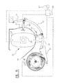
- FIG. 1 shows a schematic side view of an embodiment of a baler according to the invention adapted to execute the method according to the invention, drawn and driven by a tractor;
- FIGS. 2 and 3 show in schematic side view the feeding duct of the baler of FIG. 1 during normal operation
- FIGS. 4 to 6 show in schematic side view the feeding duct of the baler of FIG. 1 for illustrating an embodiment of the method according to the invention for removing a stuck plug of crop material from the feeder duct;
- FIG. 7 shows in schematic side view an alternative embodiment of the method according to the invention
- FIG. 8 shows in schematic side view a preferred embodiment of the feeder duct of the baler of FIG. 1 that is configured for executing the method according to the invention as illustrated by FIGS. 4 to 6 ;
- FIG. 9 shows in schematic side view the feeding duct of the baler of FIG. 8 while executing the method according to the invention as illustrated by FIGS. 4 to 6 ;
- FIG. 10 shows in schematic side view the feeding duct of the baler of FIG. 8 in case the method according to the invention as illustrated by FIGS. 4 to 6 does not succeed;
- FIG. 11 shows an alternative embodiment of the feeder duct of the baler of FIG. 1 that is configured for executing the method according to the invention as illustrated by FIGS. 4 to 6 .
- FIG. 1 shows a rectangular agricultural baler 1 .
- Baler 1 can be moved forward over ground surface 3 by means of a tractor 5 .
- In baler 1 is provided with a plunger 7 that during operation is moved reciprocally along a linear path A in bale chamber 9 by means of a crank mechanism 11 connected to plunger 7 .
- Crank mechanism 11 is connected for driving via a drive shaft 13 to the motor of tractor 5 .
- Tractor 5 is provided for this purpose with a power take-off device, also referred to as PTO.
- Drive shaft 13 connects an output shaft of the PTO of tractor 5 to an input shaft 15 of crank mechanism 11 .
- a flywheel 17 is arranged on the input shaft of the crank mechanism.
- the bale chamber 9 has an inlet opening 19 formed in the bottom wall 21 thereof.
- a feeder duct 23 communicates with the bale chamber 9 through the inlet opening 19 for charges of crop material to be transferred from the feeder duct 23 into the bale chamber 9 .
- Feeder means 25 are operable within the feeder duct 23 to accumulate a charge of crop material therein and then stuff that accumulated charge into the bale chamber 9 .
- the feeder duct 23 has an upper end 27 facing generally upwardly and communicating with the inlet opening 19 in the bale chamber 9 and a lower end 29 facing generally in a forward direction and communicating with a cutting unit 31 .
- the cutting unit 31 is arranged for cutting crop material supplied by a pick-up device 33 and to convey the cut crop material into the feeder duct 23 .
- feeder duct 23 is shown in more detail during normal operation.
- the feeder duct 23 is defined between a feeder duct top wall 35 and feeder duct bottom wall 37 .
- the feeder duct top wall 35 provides an upper boundary for the feeder duct 23 .
- the feeder duct bottom wall 37 provides a lower boundary for the feeder duct 23 .
- feeder means 25 are operable.
- the feeder means 25 include a rotatable drum 39 having sets of tines 41 , 43 arranged thereon. In operation the drum 39 is rotated in the direction of arrow B about axis of rotation 45 .
- the feeder means 25 further include a schematically shown drive 26 .
- the drive 26 is arranged for rotating the drum 39 in the direction of arrow B about axis of rotation 45 .
- the drive 26 further includes a mechanism for rotating the respective sets of tines 41 , 43 relative to the drum 39 about a respective axis of rotation 49 , 51 , while the drum 39 is rotated in the direction of arrow B about axis of rotation 45 . This causes the outer ends of the tines 41 , 43 to be moved along a path of movement.
- This path of movement may be a fixed path of movement or an adjustable path of movement, wherein the drive 26 comprises a mechanism for adjusting the path of movement of the sets of tines 41 , 43 , while the drum 39 is rotated in the direction of arrow B about axis of rotation 45 .
- the outer ends of the tines 41 , 43 are caused to be moved along a path of movement through the feeder duct 23 in the direction indicated by arrow B, thereby conveying cut crop material that has been conveyed by the cutting unit 31 (shown in FIG. 1 ) into the lower end 29 of the feeder duct 23 , from the lower end 29 of the feeder duct 23 toward the upper end 27 thereof.
- the feeder means 25 first accumulate a charge of crop material 28 in the feeder duct 23 .
- the outer ends of the tines 43 are caused to be moved along a path of movement through the feeder duct 23 in the direction indicated by arrow B, thereby stuffing, i.e. conveying, the accumulated charge of crop material 28 through the opening 19 into the bale chamber 9 .
- FIG. 4 In FIG. 4 is shown a situation wherein during accumulation of the charge of crop material 28 , a plug 30 of crop material gets stuck in the feeder duct 23 between the top wall 35 and bottom wall 37 , causing the feeding means 25 to become inoperable.
- the distance between the bottom wall 37 and the top wall 35 of the feeder duct 23 is increased by moving the bottom wall 37 away from the top wall 35 of the feeder duct 23 in the direction of arrow X while maintaining continuous the lower boundary defined by the bottom wall 37 .
- additional space is provided in the feeder duct 23 that relieves the pressure exerted on the stuck plug 30 of crop material and that allows for more movement of the stuck plug 30 of crop material and the crop material 28 downstream thereof.
- the feeder means 25 are caused to resume operation wherein the outer ends of the tines 41 , 43 are caused to move along a path of movement through the feeder duct 23 in the direction indicated by arrow B.
- the outer ends of the tines 43 are caused to be moved along a path of movement through the feeder duct 23 in the direction indicated by arrow B, thereby stuffing, i.e. conveying, the accumulated charge of crop material 28 including the dislodged plug 30 of crop material through the opening 19 into the bale chamber 9 .
- the bottom wall 37 is moved back towards the upper wall 35 of the feeder duct 23 in the direction of arrow Y, such that the feeder means 25 can accumulate a next charge of crop material in the feeder duct 23 .
- FIG. 7 is schematically shown that as an alternative to the embodiment of the method of the present invention as described under reference to FIGS. 4 to 6 , the distance between the bottom wall 37 and the top wall 35 of the feeder duct 23 is increased by moving the top wall 35 away from the bottom wall 37 of the feeder duct 23 in the direction of arrow Z while maintaining continuous the upper boundary defined by the upper wall 35 .
- a plugging of the feeder duct 23 may advantageously be prevented by increasing the distance between the bottom wall 37 and the top wall 35 of the feeder duct 23 in case there is an indication that a plugging of the feeder duct 23 is about to occur.
- increasing the distance between the bottom wall 37 and the top wall 35 of the feeder duct 23 may advantageously prevent the plugging to occur.
- FIG. 8 a preferred embodiment of the feeder duct 23 of the baler 1 of FIG. 1 is shown that is configured for executing the method according to the invention as described under reference to FIGS. 4 to 6 .
- the feeder duct is defined between a feeder duct top wall 35 and feeder duct bottom wall 37 .
- the feeder duct top wall 35 provides an upper boundary for the feeder duct 23 .
- the feeder duct bottom wall 37 provides a lower boundary for the feeder duct 23 .
- feeder means 25 are operable.
- the feeder means 25 include a rotatable drum 39 having sets of tines 41 , 43 arranged thereon. In operation the drum 39 is rotated in the direction of arrow B about axis of rotation 45 .
- the feeder means are configured for causing the outer ends of the tines to be moved along a path of movement through the feeder duct 23 , thereby conveying crop material that has been conveyed by the cutting unit 31 into the lower end 29 of the feeder duct 23 , from the lower end 29 of the feeder duct 23 toward the upper end 27 thereof.
- the cutting unit 31 is provided with cutter means in the form of a rotor 47 carrying a set of tines 49 .
- a cutting unit bottom 51 distant from the rotor 47 forms a bottom wall 51 of a conveying channel 53 through the cutting unit 31 .
- Cutting blades 55 protrude from the cutting unit bottom 51 through the conveying channel 53 .
- the rotor 47 is rotated in the direction of arrow C about axis of rotation 57 .
- Crop material fed to the cutting unit 31 by means of the pickup device 33 (shown in FIG. 1 ) in the direction of arrow D is conveyed by means of the rotor 47 through the conveying channel 53 along the cutting blades such that the crop material is cut.
- the rotor 47 conveys the cut crop material further towards the inlet of the feeder duct at the lower end 29 of the feeder duct 23 in the direction of arrow E.
- the cut crop material is engaged by the tines 41 , 43 of the feeder means for conveying the cut crop material from the lower end 29 of the feeder duct 23 toward the upper end 27 thereof in the direction of arrow F.
- the feeder duct the cut crop material is accumulated in the upper end thereof to form a charge of cut crop material.
- the feeder means 25 stuff the charge of crop material through the inlet 19 of the bale chamber 9 at the upper end 27 of the feeder duct 23 into the bale chamber 9 .
- the feeder duct 23 is provided with two doors: a front door 59 and a rear door 61 .
- the front door 59 and the rear door 61 are shown in their closed position.
- the front door 59 is formed by a lower end part of the bottom wall 37 .
- the front door 59 extends between an inlet 63 of the feeder duct 23 at the lower end 29 thereof and the rear door 61 .
- Front door 59 is at one edge 65 thereof attached to the bottom wall 51 of the cutting unit 31 .
- the other edge 67 of the front door 59 is adjacent an edge 69 of the rear door 61 . As shown in FIG. 8 , the adjacent edges 67 , 69 overlap in the closed position of the doors 59 , 61 .
- the rear door 61 is formed by a central part of the bottom wall that extends between the front door 59 and an upper end part 71 of the bottom wall 37 .
- the rear door 61 has one edge 69 adjacent the front door 59 .
- the rear door is hingedly attached to the upper end part 71 of the bottom wall 37 by means of a hinge 75 defining a pivot axis 77 .
- the upper end part 71 of the bottom wall 37 is at its edge 79 opposite to the edge 73 to which the rear door 61 is attached, hingedly attached at the end 27 of the feeder duct 23 near the inlet 19 of the bale chamber 9 by means of a hinge 81 defining a pivot axis 83 .
- Rear door 61 and the upper end part 71 of the bottom wall to which the rear door 61 is hingedly attached are held in the closed position thereof by means of a first latch 85 engaging the rear door 61 near its edge 69 that is adjacent the front door 59 , and by means of a second latch 87 engaging the upper end part 71 of the bottom wall 37 near its edge 89 to which the rear door 61 is hingedly attached.
- Front door 59 is at one edge 65 thereof held in the closed position by being attached to the bottom wall 51 of the cutting unit 31 .
- the front door 59 is held in the closed position by means of the first latch 85 by virtue of a stepped overlap between the edge 67 of the front door 59 and the edge 69 of the rear door 61 , wherein the edge 69 of the rear door 61 engages underneath the edge 67 of the front door 59 .
- the first latch 85 is provided with a lever 91 , that allows the point where the first latch 85 engages the rear door 61 to be manually moved away from the top wall 35 of the feeder duct 23 in the direction of arrow G, thereby moving the rear door 61 away from the top wall 35 of the feeder duct 23 in the direction of arrow H by rotation about the axis of rotation 77 .
- the upper end part 71 of the bottom wall 37 may be moved by means of the second latch 87 .
- the second latch 87 is provided with a lever 93 , that allows the point where the second latch 87 engages the upper end part 71 of the bottom wall 37 to be manually moved away from the top wall 35 of the feeder duct 23 in the direction of arrow G′, thereby moving the upper end part 71 of the bottom wall 37 away from the top wall 35 of the feeder duct 23 in the direction of arrow H′ by rotation about the axis of rotation 83 .
- the bottom wall 51 of the cutting unit 31 is hingedly attached to a frame part of the baler by means of a hinge 95 defining a pivot axis 97 , and movable by means of a linear actuator 99 in the direction of arrow I away from the rotor cutter 47 .
- a linear actuator 99 By moving the bottom wall 51 of the cutting unit 31 by means of a linear actuator 99 in the direction of arrow I, the front door 59 that is attached to the bottom wall 51 of the cutting unit 31 can be moved away from the top wall 35 of the feeder duct 23 in the direction of arrow I.
- the front door 59 and rear door 61 are in the shown closed position.
- the front door 59 , the rear door 61 , and upper end part 71 of the bottom wall 37 are moved away from the top wall 35 of the feeder duct 23 by means of the linear actuator 99 and the latches 85 , 87 , thereby increasing the distance between the top wall 35 and the bottom wall 37 of the feeder duct 23 .
- the front door 59 , the rear door 61 , and the upper end part 71 of the bottom wall 37 are position in a partly opened position.
- the latches 85 , 87 thus provide means adapted for selectively moving the rear door 61 and the upper end part 71 of the bottom wall 37 between a closed position and a partly opened position.
- the linear actuator 99 provide means adapted for selectively moving the adjacent front door 59 between a closed position and a partly opened position.
- the front door 59 , rear door 61 and upper end 71 of the bottom wall 37 thus are sections of the bottom wall 37 , that are movable relative to the top wall 35 of the feeder duct 23 .
- the adjacent sections formed by the rear door 61 and upper end 71 of the bottom wall 37 are mutually hingedly attached along adjacent edges, such that when moving the rear door 61 and upper end 71 of the bottom wall 37 the adjacent edges of the rear door 61 and upper end 71 of the bottom wall 37 remain adjacent to one another, such that no opening of the part of the lower boundary provided by the rear door 61 and upper end 71 of the bottom wall 37 results.
- the linear actuator 99 and the latches 85 , 87 are configured to move the front door 59 , the rear door 61 and upper end 71 of the bottom wall 37 into the partly opened position in such a way, that the adjacent edges of the adjacent sections formed by the front door 59 and the rear door 61 despite not being mutually hingedly attached remain adjacent to one another, such that no opening of the part of the lower boundary provided by the front door 59 and the rear door 61 results.
- the space in the feeder duct is increased relative to the situation shown in FIG. 8 with the front door 59 and rear door 61 in the closed position thereof.
- the increased space in the feeder duct 23 releases the pressure on the plug of crop material and provides additional space for the plug of crop material to move.
- the front door 59 , rear door 61 , and upper end part 71 of the feeder duct 23 can be positioned in an open position in which they do no longer provide the lower boundary of the feeder duct 23 .
- the rear door 61 is releasable from the first latch 85
- the upper end part 71 of the bottom wall 37 is releasable from the second latch 87 , such that the rear door 61 and the upper end part of the bottom wall 71 can be moved further away from the top wall of the feeder duct in the direction of arrow H and H′.
- the front door 59 can be moved further away from the top wall 35 of the feeder duct 23 by further moving the bottom wall 51 of the cutting unit 31 by means of the linear actuator 99 in the direction of arrow I. The result is shown in FIG. 10 .
- a plug of crop material stuck in the feeder duct 23 can in this position of the front door 59 , rear door 61 , and upper end part 71 of the feeder duct discharge onto the ground underneath the feeder duct 23 through the opening 103 between the adjacent edges 65 , 67 of the front door 59 and the rear door 61 , either under influence of its own weight or by additional dislodging, for instance by oscillating or rocking the drive train 13 , 15 , 17 (shown in FIG. 1 ) to the feeder means.
- the front door 59 , rear door 61 , and upper end part 71 of the feeder duct can be positioned in the closed position again.
- the front door 59 can be positioned in the closed position by means of the linear actuator 99 .
- the rear door 61 and upper part 71 of the bottom wall 37 can be positioned in the closed position by engaging the first and second latches 85 , 87 and subsequently operating the latches 85 , 87 to move the rear door 61 and upper part 71 of the bottom wall 37 into the closed position.
- FIG. 11 an alternative embodiment of the feeder duct 23 of the baler 1 shown in FIGS. 8 to 10 is shown, wherein the manually operated, first and second latches 85 , 87 , have been replaced by a first and second linear actuator 185 , 187 .
- the first and second linear actuators 185 , 187 replace the latches as means for holding the rear door 61 and the upper end part 71 of the bottom wall to which the rear door 61 is hingedly attached in the closed position.
- the linear actuators 185 , 187 are adapted for selectively moving the rear door 61 and the upper end part 71 of the bottom wall to which the rear door 61 is hingedly attached between the shown closed position and the partly opened position shown in FIG. 9 .
- the linear actuators 185 , 187 , as well as the linear actuator 99 , are connected to a controller 105 for controlling the linear actuators 99 , 185 , 187 .
- Sensor means 107 are provided, that are connected to the controller 105 and adapted for detecting plugging of the feeder duct 23 .
- the controller 105 is configured of controlling the linear actuators, 99 , 185 , 187 such that the front door 59 , the rear door 61 , and the end part 71 of the bottom wall 37 are moved into the partly opened position that is shown in FIG. 9 when a plugging of the feeder duct 23 is detected by said sensor means 107 .
- the rear door 61 is releasable from the first linear actuator 185
- the upper end part 71 of the bottom wall 37 is releasable from the second linear actuator 187 , such that the rear door 61 and the upper end part of the bottom wall 71 can be moved into the opened position that is shown in FIG. 9 .
- the first linear actuator 185 and the second linear actuator 187 are configured and arranged for moving the rear door 61 and the upper end part 71 of the bottom wall 37 from the partly opened position that is shown in FIG. 9 into the opened position that is shown in FIG. 10 .
- the controller 105 is also connected to the drive 26 of the feeder means 25 .
- the controller 105 may be configured for causing the drive 26 to stop the operation of the feeder means 25 when a plugging of the feeder duct 23 is detected and for causing the drive 26 to resume the operation of the feeder means 25 after the front door 59 , the rear door 61 , and the end part 71 of the bottom wall 37 have been moved into the partly opened position.
- the sensor means 107 may be configured to detect the location along the feeder duct 23 where the plugging has occurred. This would allow the controller 105 to be configured to only cause the rear door 61 , and the end part 71 of the bottom wall 37 to be moved into the partly opened position when the plugging is detected in the end part of the feeder duct 23 .
Landscapes
- Life Sciences & Earth Sciences (AREA)
- Environmental Sciences (AREA)
- Harvester Elements (AREA)
- Fertilizing (AREA)
- Combines (AREA)
Abstract
Description
Claims (15)
Applications Claiming Priority (2)
| Application Number | Priority Date | Filing Date | Title |
|---|---|---|---|
| BE2015/5677 | 2015-10-20 | ||
| BE2015/5677A BE1023244B1 (en) | 2015-10-20 | 2015-10-20 | AGRICULTURAL BALL PRESS AND METHOD FOR PREVENTING AND REMOVING A Clogging in the feed tube of an agricultural baler |
Publications (2)
| Publication Number | Publication Date |
|---|---|
| US20170105354A1 US20170105354A1 (en) | 2017-04-20 |
| US9907232B2 true US9907232B2 (en) | 2018-03-06 |
Family
ID=55221181
Family Applications (1)
| Application Number | Title | Priority Date | Filing Date |
|---|---|---|---|
| US15/299,057 Active US9907232B2 (en) | 2015-10-20 | 2016-10-20 | Agricultural baler and method for preventing and removing a plugging in the feeder duct of an agricultural baler |
Country Status (4)
| Country | Link |
|---|---|
| US (1) | US9907232B2 (en) |
| EP (2) | EP3300588B1 (en) |
| BE (1) | BE1023244B1 (en) |
| BR (1) | BR102016024324B1 (en) |
Cited By (5)
| Publication number | Priority date | Publication date | Assignee | Title |
|---|---|---|---|---|
| US20180317395A1 (en) * | 2015-10-20 | 2018-11-08 | Cnh Industrial America Llc | Agricultural Baler |
| US10645875B2 (en) * | 2017-10-19 | 2020-05-12 | Cnh Industrial America Llc | Method and system for unloading harvested crop from an agricultural harvester |
| US11044851B2 (en) * | 2016-12-16 | 2021-06-29 | Agco Corporation | Adjustable stuffer chute |
| US11191216B2 (en) * | 2016-12-14 | 2021-12-07 | Mchale Engineering | Conveying device and a method for conveying material, through a conveying channel |
| US20210400880A1 (en) * | 2020-06-30 | 2021-12-30 | Deere & Company | Large square baler with pre-compression chamber having removeable access panel |
Families Citing this family (1)
| Publication number | Priority date | Publication date | Assignee | Title |
|---|---|---|---|---|
| EP3662743B1 (en) * | 2018-12-03 | 2023-02-08 | CNH Industrial Belgium NV | An agricultural baler |
Citations (6)
| Publication number | Priority date | Publication date | Assignee | Title |
|---|---|---|---|---|
| US4275550A (en) | 1979-10-15 | 1981-06-30 | Hesston Corporation | Crop baler |
| US4569282A (en) | 1983-03-22 | 1986-02-11 | Regie Nationale Des Usines Renault | Plunger hay baler |
| US4862684A (en) | 1988-01-21 | 1989-09-05 | Ford New Holland, Inc. | Variable feeder duct for balers |
| US4956967A (en) * | 1988-04-28 | 1990-09-18 | Ford New Holland, Inc. | Agricultural baler with feeder door |
| US4962632A (en) | 1988-04-28 | 1990-10-16 | Ford New Holland, Inc. | Agricultural baler with movable feeder floor |
| WO2014129892A1 (en) | 2013-02-22 | 2014-08-28 | Forage Innovations B.V. | Conveying arrangement with knives which can be pivoted vertically and shifted laterally |
-
2015
- 2015-10-20 BE BE2015/5677A patent/BE1023244B1/en active
-
2016
- 2016-10-18 BR BR102016024324-6A patent/BR102016024324B1/en not_active IP Right Cessation
- 2016-10-19 EP EP17197692.1A patent/EP3300588B1/en active Active
- 2016-10-19 EP EP16194624.9A patent/EP3158856B1/en active Active
- 2016-10-20 US US15/299,057 patent/US9907232B2/en active Active
Patent Citations (7)
| Publication number | Priority date | Publication date | Assignee | Title |
|---|---|---|---|---|
| US4275550A (en) | 1979-10-15 | 1981-06-30 | Hesston Corporation | Crop baler |
| US4569282A (en) | 1983-03-22 | 1986-02-11 | Regie Nationale Des Usines Renault | Plunger hay baler |
| US4862684A (en) | 1988-01-21 | 1989-09-05 | Ford New Holland, Inc. | Variable feeder duct for balers |
| US4956967A (en) * | 1988-04-28 | 1990-09-18 | Ford New Holland, Inc. | Agricultural baler with feeder door |
| US4962632A (en) | 1988-04-28 | 1990-10-16 | Ford New Holland, Inc. | Agricultural baler with movable feeder floor |
| WO2014129892A1 (en) | 2013-02-22 | 2014-08-28 | Forage Innovations B.V. | Conveying arrangement with knives which can be pivoted vertically and shifted laterally |
| US20160001294A1 (en) | 2013-02-22 | 2016-01-07 | Forage Innovations B.V. | Conveying arrangement with knives which can be pivoted vertically and shifted laterally |
Non-Patent Citations (1)
| Title |
|---|
| EP16194624, Extended European Search Report, dated Mar. 16, 2017, 12 pages. |
Cited By (7)
| Publication number | Priority date | Publication date | Assignee | Title |
|---|---|---|---|---|
| US20180317395A1 (en) * | 2015-10-20 | 2018-11-08 | Cnh Industrial America Llc | Agricultural Baler |
| US10485182B2 (en) * | 2015-10-20 | 2019-11-26 | Cnh Industrial America Llc | Agriculture baler |
| US11191216B2 (en) * | 2016-12-14 | 2021-12-07 | Mchale Engineering | Conveying device and a method for conveying material, through a conveying channel |
| US11044851B2 (en) * | 2016-12-16 | 2021-06-29 | Agco Corporation | Adjustable stuffer chute |
| US10645875B2 (en) * | 2017-10-19 | 2020-05-12 | Cnh Industrial America Llc | Method and system for unloading harvested crop from an agricultural harvester |
| US20210400880A1 (en) * | 2020-06-30 | 2021-12-30 | Deere & Company | Large square baler with pre-compression chamber having removeable access panel |
| US11382277B2 (en) * | 2020-06-30 | 2022-07-12 | Deere & Company | Large square baler with pre-compression chamber having removeable access panel |
Also Published As
| Publication number | Publication date |
|---|---|
| BE1023244B1 (en) | 2017-01-06 |
| US20170105354A1 (en) | 2017-04-20 |
| EP3158856A1 (en) | 2017-04-26 |
| BR102016024324B1 (en) | 2021-10-26 |
| BR102016024324A2 (en) | 2017-05-02 |
| EP3300588A1 (en) | 2018-04-04 |
| EP3300588B1 (en) | 2019-08-21 |
| EP3158856B1 (en) | 2018-12-19 |
Similar Documents
| Publication | Publication Date | Title |
|---|---|---|
| US9907232B2 (en) | Agricultural baler and method for preventing and removing a plugging in the feeder duct of an agricultural baler | |
| EP3364742B1 (en) | Agricultural baler | |
| US10485182B2 (en) | Agriculture baler | |
| US9756790B2 (en) | Agricultural baler and method for removing a plug of crop material stuck in the feeder duct of an agricultural baler | |
| EP2992753A1 (en) | Harvester with rear active bottom floor | |
| EP3515177B1 (en) | Apparatus and method for forming and ejecting a bale depending on a ramp sensor | |
| EP3158855B1 (en) | Rotor feeder unit for agricultural machines and method for operating a rotor feeder | |
| DE102014008068B4 (en) | Self-propelled forage harvester | |
| EP3590324B1 (en) | Loader wagon and method for unloading a loader wagon | |
| JP2003125643A (en) | Conveyer for roll baler | |
| BR102022026681A2 (en) | SYSTEM FOR DETECTING A CONDITION INDICATIVE OF CLOGGING IN AN AGRICULTURAL COMBINATION |
Legal Events
| Date | Code | Title | Description |
|---|---|---|---|
| STCF | Information on status: patent grant |
Free format text: PATENTED CASE |
|
| AS | Assignment |
Owner name: CNH INDUSTRIAL AMERICA LLC, PENNSYLVANIA Free format text: ASSIGNMENT OF ASSIGNORS INTEREST;ASSIGNOR:CNH INDUSTRIAL BELGIUM NV;REEL/FRAME:044984/0969 Effective date: 20161017 |
|
| AS | Assignment |
Owner name: CNH INDUSTRIAL BELGIUM NV, BELGIUM Free format text: ASSIGNMENT OF ASSIGNORS INTEREST;ASSIGNORS:KINDT, DIETER;ROSSEEL, BRAM;REEL/FRAME:047805/0053 Effective date: 20151020 Owner name: CNH INDUSTRIAL BELGIUM NV, BELGIUM Free format text: ASSIGNMENT OF ASSIGNORS INTEREST;ASSIGNORS:DEVROE, JEROEN;LIEFOOGHE, DRIES;REEL/FRAME:047950/0074 Effective date: 20151020 |
|
| AS | Assignment |
Owner name: BLUE LEAF I.P., INC., DELAWARE Free format text: ASSIGNMENT OF ASSIGNORS INTEREST;ASSIGNOR:CNH INDUSTRIAL AMERICA LLC;REEL/FRAME:048973/0770 Effective date: 20190117 |
|
| MAFP | Maintenance fee payment |
Free format text: PAYMENT OF MAINTENANCE FEE, 4TH YEAR, LARGE ENTITY (ORIGINAL EVENT CODE: M1551); ENTITY STATUS OF PATENT OWNER: LARGE ENTITY Year of fee payment: 4 |
|
| MAFP | Maintenance fee payment |
Free format text: PAYMENT OF MAINTENANCE FEE, 8TH YEAR, LARGE ENTITY (ORIGINAL EVENT CODE: M1552); ENTITY STATUS OF PATENT OWNER: LARGE ENTITY Year of fee payment: 8 |