US990509A - Photographic shutter. - Google Patents
Photographic shutter. Download PDFInfo
- Publication number
- US990509A US990509A US41744208A US1908417442A US990509A US 990509 A US990509 A US 990509A US 41744208 A US41744208 A US 41744208A US 1908417442 A US1908417442 A US 1908417442A US 990509 A US990509 A US 990509A
- Authority
- US
- United States
- Prior art keywords
- shutter
- lever
- master
- retarder
- detent
- Prior art date
- Legal status (The legal status is an assumption and is not a legal conclusion. Google has not performed a legal analysis and makes no representation as to the accuracy of the status listed.)
- Expired - Lifetime
Links
Images


Classifications
-
- G—PHYSICS
- G03—PHOTOGRAPHY; CINEMATOGRAPHY; ANALOGOUS TECHNIQUES USING WAVES OTHER THAN OPTICAL WAVES; ELECTROGRAPHY; HOLOGRAPHY
- G03B—APPARATUS OR ARRANGEMENTS FOR TAKING PHOTOGRAPHS OR FOR PROJECTING OR VIEWING THEM; APPARATUS OR ARRANGEMENTS EMPLOYING ANALOGOUS TECHNIQUES USING WAVES OTHER THAN OPTICAL WAVES; ACCESSORIES THEREFOR
- G03B9/00—Exposure-making shutters; Diaphragms
- G03B9/08—Shutters
- G03B9/10—Blade or disc rotating or pivoting about axis normal to its plane
- G03B9/18—More than two members
- G03B9/22—More than two members each moving in one direction to open and then in opposite direction to close, e.g. iris type
Definitions
- WITNESS-s v QINVENTom 1H: Ncnms Perales ca, wasmncmrl. s. c
- rlhis invention relates to photographic shutters, and more particularly to automatic shutters that are adapted to make time and bulb exposures, and instantaneous exposures of different lengths.
- rlhe object of the invention is to produce an efficient device of this character that is exceedingly compact and in which all the working parts, except parts of the regulator, pump connection and finger lever, are inclosed in the shutter casing.
- novel feature of the device resides in an arrangement whereby, upon a single movement of the indicating pointer, the shutter is thrown open and locked in that position for the purpose of focusing an image upon the ground-glass of a camera.
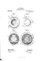
- FIG. 1 is a front elevation of the complete mechanism
- Fig. 2 is a front elevation of a part hereinafter designated as the cam plate set for a time exposure, as it would appear were the front plate of the shutter-case removed
- Fig. 3 is a front view of the shutter with all the parts removed except the shutter blades
- Fig. 4 is a similar view with certain parts in place which are omitted from Fig. 8
- Figs. 5, 6, and 7, are similar views, with additional parts in place
- Fig. 8 is a vertical section on the line 8 8 of Fig. 7
- Fig. 9 is a view showing the same parts as Fig. 4, when the shutter is open during an instantaneous exposure
- Fig. 4 is a front elevation of the complete mechanism
- Fig. 3 is a front view of the shutter with all the parts removed except the shutter blades
- Fig. 4 is a similar view with certain parts in place which are omitted from Fig. 8
- Figs. 5, 6, and 7, are similar
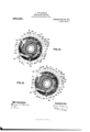
- Fig. 10 shows the shutter after the first movement for a time exposure, certain parts being removed;
- Fig. 11 shows the same after the second movement for time exposure, but before the shutter has closed;
- Fig. 12 shows the same parts after the first movement of a bulb exposure;
- Fig. 13 shows the same parts after the finger-lever is released in a bulb exposure, but before the shutter has closed;
- Figs. 14 and 15 show the Specification of Letters Patent.
- Fig. 16 shows the parts illustrated in Fig. 2, when set to hold the shutter open for focusing;
- Fig. 17 is the same when set for a bulb exposure;
- Figs. 18 and 19 are the same parts, set for fast and slow instantaneous exposures, respectively; and
- Fig. 2O is a front elevation of the master-lever.
- he shutter casing 1 is circular, and of sufficient depth to contain all the moving parts.
- the front plate 2, on which are the scales 2a and 2b, for the setting of the shutter and of the iris diaphragm, respectively, is fastened to the body (Fig. 8) of the casing 1 in any suitable manner.
- iris diaphragm 5 Fixed to the inside of the back of the casing are two plates 8 and 4, perforated to permit passage of light through the lens.
- the iris diaphragm 5 is supported between these two plates, and is operated by an arm 6 which extends through a suitable slot 7 in the lower edge o-f the casing 1 and has an upturned end in proximity to the scale 2b (Fig. 1).
- Projecting forwardly from the back-plate 4 are the pivots upon which are hung all the moving parts of the device.
- the shutter blades 9, 9, (Fig. 3) which constitute the shutter proper. Said blades are adapted to move in opposite directions, and are operated simultaneously by the movement of the shutter lever 10 (Fig. 4) that is pivoted at 11.
- the lever 10 carries at its upper end a pin 12 which projects into diagonally-disposed slots 13, 13, one in the upper part of each shutter-blade 9, 9.
- the upward movement of the shutter lever' 10 causes the blades 9, 9 to move away from each other, thus admitting light to the lens, and the downward movement of said lever, which is accomplished by the action of a spring 14, causes the blades 9, 9 to approach each other, thus cutting' off light from the lens.
- a lug 15 Upon the lower extremity of the lever 10 is a lug 15, that is adapted to be engaged by a master-lever 1G hung upon a pivot 17 (Figs. 5 and 20).
- the lug 15 is beveled on its trent tace so that as the master-lever 1G moves tovvard the right, the spring arm 1Ga or the master-lever slides up the bereled face ot' said lug and no movement or the arm 10 results.
- the lug 15 On the mov-ement ot the master-lever 1G toward the lett., the lug 15 is engaged by said lever, and the arm 10 is moved about its pivot 117 thus carrying the pin 1Q upward and opening the bladesl t), 9; and since the master-lever 1G and the shutter lever 10 are not concentric, the arm 1Ga vvill slip off the lug 15 and release the sluitter blad-es so that they can close under the action ot the shutter spring 1st.
- Pivoted at 1S upon the master-lever 18 is a bar 19 (Fig ⁇ hereinafter designated as the retarder-actuator, Aits loWer end has tvvo points 2O and Q1.
- the point Q0 is held against a projection 22 on the master-lever 1G by means of a spring that is coiled about the pivot 17. Said spring at all times tends to move said bar 19 and, therefore, the master-l ever also, toward the lett, which motion. it' permitted to occur, causes the opening of the shutter7 before described.
- rlhe point 21 ot the bar 19 is adapted, in certain positions, to engage the extremity 2l of a retarder lever' E25 that is pivoted at QG.
- the left end of said lever 25 is pivotally attached to a plunger 27 of a dash-pot QS, which constitutes a retarder that is brought into operation during all except the shortest instantaneous exposures of the shutter.
- the dash-pot 28 swings on a pin Q9, obviating the necessity of a link connection betvveen the plunger QT and the lever 25.
- a retarder motor such as the spring 30, Wound upon the pivot QG and reacting against a pin 31, tends to pull the plunger 27 out ot the dash-pot QS by pressing against a projection 32 on the lever Q5.
- ileans vvhich normally prev-ent the latter occurrence are provided as follows: On the pivot 17 (Fig. ll) is a lever 34 that has an upwardly projecting portion 35, in which is a stud Bti. Said stud is acted upon by a spring 23T. which tends to move the upper' end or arm 34e ot the lever Si toward the lett. This motion .is controlled by the cam plate betore mentioned, vvhich is clearly illustrated in Figs. 16.r 17.y 1S and 19.
- Said cani plat-e is a ring Btl, surrounding a collar 53.() that is screived upon the trout plate Q.
- Said ring or cam plate is revolved around said collar by means ot the controlling lever or indicating-pointer arm 10, which, in the press ent case, is integral with the ring.
- 'lfl'ie greatest part of the outer periphery ot the am plate 3S is concentric vvith the inner periphery thereof, but a certain portion is formed into a cam curve 41, the center ot which is not coincident with the center ot the said plate.
- This curvetl there'ttue constitutes a cam, which engages the stud 16 aforesaid, and moves the latter away troni the center oit the shutter when the controlling lever or indicating-pointer Lt0 is carried tovvard the right. llflhen said pointer is moved tovv; rd the lett. the stud 3G is held closely against the cam Lt1 by the action oit the spring Si.
- the innermost end ot the curve 11 is a slight projection 1Q, and beyond said projection a notch elli, the bottoni oit which is much nearer to the center of the cani plate 3S than is any portion oit the curve wi1.
- the pointer 1Y0 is moved to the extreme lett, so that it rests at O on the scale 2', the stud 36 rides over the projection and is forced into the notch -lby the action ot' the spring 25T 1(5). lllhen this movement occurs, the upper end Erle" oit the lever 3st presses against the lug 13 of the shutter lever 10 and the latter is moved thereby, throwing open the shutterblades f), 9.
- cam lll. i normally held out oit operation, and the lever 3%!- With its lovver end 30 is the retarder-controller.
- the action ot the rctarder parts, as att'ecting instantaneous exposures7 will be described below.
- the master-lever lo has a lug itlV on its upper end, adjacent to its pivot 1H, and this lug is adapted to be engaged by the upper end -15 ot' the trip lever liti (Fig. (3). Said trip lever pivoted at il?, and hasl au elongated loiver end 18, which. by striking the stationary pin 31, limits the movement ot the trip lever in one direction.
- the trip lever 1G is ctuated to move the master-lever 1G by means ot an 4operating lever -l-S) (Fig. T), that is pivoted upon the piu 11.
- Said operating lever may be moved about the pin 11 either by means ot' the tinger-lever o() which. when depressed. acts ou the lug 51. on the oi erating lever -l-). or bv means ot' the pump 52, the plunger .ot which strikes the lower end ot' said lever lli). and is operated by air treni a compressible bulb as usual and attached to the connectingtip 53.
- the tinger 5ft slips otta tbe upger edge ot the lug M7. and the spring 23 Fig. 5) carries the master-lever 16, and therefore the trip lever 46 also, back toward the left (Fig. 12). Said master-lever then engages the lug 15 on the shutter arm 19, and holds the shutterblades 9, 9 open until the lower end 48 of the trip lever 46 is stopped by the pin 31, at which point the upper end oir the masterlever has moved so far that its arm 16a has disengaged from the lug 15 of the shutter arm 10, and this permits the spring 14 to close the shutter-blades again.
- Means are provided for the purpose of making time 7 and bulb 7 exposures, whereby the master-lever 16 is retained at will in such a position that the lug 15 rests upon its upper end, thereby holding the shutter-blades open until said master-lever is permitted to move farther toward the left, when it will be clear of said lug and the shutter may close.
- the time detent 57 On the pivot 56 which carries the fingerlever 50, is hung the time detent 57, normally pressed downward by a spring 58 that engages a pin 59 on the detent (Fig. ln the extremity of said detent is a notch 6G, and below said notch is a shoulder 61, which is adapted to engage a lug 62 on the upper end of the master-lever 16, and to stop the return of the lat-ter, so as to hold the shutter open.
- a lug 63 Extending rearwardly from the operating lever 49 is a lug 63 (Fig. 7), which, in the normal position of said lever, rests outside of but near the notch 60 aforesaid.
- the lug 63 enters the notch 69 (Fig. 11), and, engaging the side thereof, raises the time detent 57 against the action of the spring 58, and prevents said detent from stopping the return of the master-lever 16.
- the bulb detent 64 is hung upon the pivot 56, in front of the time detent 57, and is normally pressed downward by a spring 65 that engages a lug 66 on the same. rIhe end 67 of the bulb detent 64 is adapted to engage the lug 62 on the master-lever 16 when depressed by the spring 65. Normally, however, said bulb detent is held up to the position shown in Fig. 6 by means of a shoulder 68 on the operating lever 49 that supports the lug 66. )When said operating lever is depressed, the said shoulder 68 moves downward, and the spring 65 presses the bulb detent 64 downward also. As the operating lever 49 is returned to no-rmal position (Fig. 7), by means of the spring 49a, the shoulder 68 thereon strikes the under side of the projection 66, and raises the end 67 of the bulb detent out of the path of the lug 62 on the master-lever 16.
- rlhe cam plate 38 has in its edge, near the indicating-pointer 40, a notch 69.
- the pin 59 on the time detent and the projection 66 on the bulb detent both rest in said notch (Fig. 2), and the detents 57 and 64 may then operate as described.
- the pin 59 rides up on the periphery of the cam plate at 70, and the time detent is thus held up and out of normal operation (Fig. 17).
- Further movement of the pointer 40 to 1/100 on the scale brings the portion under the projection 66 on the time detent 64 (Fig. 18), and thus raises the lat-ter out of the path of the lug 62 on the master-lever 16, as before described.
- rlhe operation ot' the parts for a time exposure is as follows: The pointer 40 is moved to T on the scale 2a. rlhe lingerlever 50 being depressed, strikes the lug 51 and moves the operating lever 49 about its pivot 11, causing the tripping finger 54 to engage the lug 55 on the trip lever 46. Said trip lever is thus swung toward the right, and its upper end 45 presses against the lug 44 on the master-lever 16 and so moves the latter in the same direction. rlhe upper end of said master-lever slips over the beveled edge of the lug 15 on the shutter lever 10, and continues its motion until the tripping linger 54 slips past the lug 55.
- the spring 23 throws the master-lever 16 toward the left, and the upper end thereof strikes the right side of the lug 15 and opens the shutter-blades 9, 9.
- the lug 63 on the operating lever engages the time detent 57 and raises it, while the shoulder 68 on said lever moves downward, allowing the spring 65 to move the end 67 of the bulb detent 64 into t-he path of the lug 62.
- the master-lever 16 is thus stopped, and the shutter held open.
- the operating lever 49 Upon releasing the finger-lever 50 the operating lever 49 is moved upward by means of its spring 49, carrying with it the bulb detent 64, and causing the end 67 of the latter to rise out of the path or" the lug 62. But this does not permit the master-lever 16 to slip from under the lug 15 on the shutter arm, for during the time that the detent 64 is being carried upward, the lug 63 on the operating lever 49 is moving downward, and the spring 58 forces the time detent 57 downward also.
- the detent 64 projects slightly beyond the shoulder (i1 on the detent 57.
- the detent (il being thus rendered inoperative, and the detent 57 being carried uilriward by the lng (33 otl the operating lever Lt9, there is nothing in the path of the lug (S2 to prevent its further movement, and the master-lever 16 is therefore carried (by the aetion ot the spring 28) past the bottom ot the shutter lever (see Fig. 11), and the spring 1-1 connected thereto immediately causes the shutter-blades 9, 9, to close.
- the master-lever 16 engages the lug and moves the shutter lever 10, open ing the blades 9, 9.
- the lug (32 then strikes the end o1'l the bulb detent (3st-, and the masterlever is held stationary, the shutter lever 10 resting upon its upper end and retaining the shutter-blades open as long as the iingerlever is held down.
- the bulb detent (S11- is carried upward by the engage-- ment ot the shoulder (5S of the operating lever with the lng G6 on said detent, and the master-lever 16 may their iinish its movement, passing from under the shutter lever l() (see 13) and permitting the blades 9, 9, to close.
- the indicating-pointer Ll0 is placed at 1/100 i on the scale 2, the pin 59 and the projection (3G both rest upon the top of the portion ot the cam plate 3S, thereby holding the detents 5T and (3i-t out ot. action (lffig. 1S).
- the master-lever 1G moves toward the right, the point 21 of the retardei.'-aetua tor slips over and rests upon the top et' the lug 251-, and when said master-lever moves bael toward the lett (which movement opens the shutter), the point 21 moves downward and depresses the short end of the retarder lever 25. rlhe end of said lever to which the plunger Q7 is attached is thus moved npward, and said plunger presses against the cushion et air in the dash-pot 2S.
- the plunger 2T tits the dash-pot 28 rather loosely, and the air contained in said dash-pot may theretore leak out slowly past said plunger, permitting the latter to move upward slowly.
- the length of time that is required to push the plunger 27 into the dash-pot Q8 is directly proptn'tional to the extent to which it is pulled out of said dash-pot.
- the latter movement is determined by the position ot the lower' end 341') ot the retarder-controller
- the retarder-eontroller, as betere described, is moved to att'cctthe ietarderdever 25 by the engagement etl the curve t1 on the cam plate with the stud 3G.
- the trip lever t6 is intermediate between the master lever 16 and the operating lever 49, and that the stop for the trip lever, in its normal position of rest, is the pin 31, lwhile the stop for the master-lever, in its normal position of rest, is the post or pin et?. lhen the shutter is setl for one of the slower instantaneous speeds, the operating lever in its return movement, under the iniiuence of its springs 49 (see Fig. 7), does not apply any force to the master-lever that would vtend to change and increase the speed of the masterlever and of the shutter, but leaves the master-lever free to act under the influence of its own spring and the retarder.
- T he force of the operating lever in its said return movement is applied through the tripping finger 54 and the lug 55 to the trip lever 46, which may move with the operating lever independently of and away from the masterlever.
- the independence of the trip lever i6 produces a certainty of speed of action which could not occur if the operating lever in its return movement had any contact with the master-lever directly.
- iVhat claim is l.
- a spring closed shutter a master-lever for opening the shutter having connect-ions with the shutter including a slip-off device; a trip lever engaging the master-lever; an operating lever having a slip-off connection with the trip lever; a retarder; a retarder lever; a retarder actuator engaging the master-lever and the retarder lever; a retardercontroller for varying the action of the retarder; a bulb detent for stopping the master-lever with the shutter open; means for releasing the bulb detent upon a release action of the operating lever; a time detent for stopping' the master-lever after release from the bulb detent; means for disengaging the time detent by a separate action of the operating lever; and setting means for throwing the time detent out of action, for throwing both detents out of action, for varying the action of the retarder-controller, and for locking the operating lever against action when the shutter is open for focusing.
- a spring closed shutter a master-lever for opening the shutter having connections with the shutter including a slip-off device; a trip lever engaging the master-lever; an operating lever having a slip-off connection with the trip lever; a retarder; a retarder lever; a retarder actuator engaging the masterlever and the retarder lever; a retarder controller for stopping the movement of the retarder lever at variable stopping points; a bulb detent for stopping the master-lever with the shutter open; a time detent for stopping the master-lever after 'release from the bulb detent; means for disengaging the detents by the operating lever; and setting means for throwing one or both detents out of act-ion and for varying the action of the retarder controller.
- a photographic shutter mechanism a shutter; a spring-actuated shutter lever for closing the shutter; a master-lever for opening the shutter having a slip-off connection with the shutter lever; a trip-lever engaging the master-lever; an operating lever having a slip-off connection with the trip lever; a retarder; a retarder lever; a retarder actuator engaging the master-lever and the retarder lever; a retarder controller for varying the action of the retarder; a bulb detent for stopping the master-lever with the shutter open; means for releasing the bulb detent upon a release action of the operating lever; a time detent for stopping the master-lever after release from the bulb detent; means for disengaging the time detent b-y a separate action of the operating lever; and setting means for throwing the time detent out of action, for throwing bot-h detents out of action, for varying the action of the retarder-controller, and for locking the operating lever against action when the shutter is open for focusing.
- a shutter a spring actuated shutter lever for closing the shutter; a master-lever for opening the shutter having a slip-oif connection with the shutter lever; a trip lever engaging the master-lever; an operating lever having a slip-off connection with the trip lever; a retarder; a retarder lever; a retarder actuator engaging the master-lever and the retarder lever; a retarder controller for stopping the movement of the retarder lever at variable stopping points; a bulb detent tor stopping the master-lever with the shutter open; a time detentfor stopping the master-lever after release trom the bulb detent; means tor disengaging the detents by the operating lever; and setting means tor throwing one or both detents out ot action and tor varying the action ot the retarder controller.
- a photographic shutter mechanism a spring closed shutter; a master-lever tor opening the shutter having connections with the shutter including a slip-ott' device; a trip lever engaging the master-lever; an operating lever having a slip-ott connection with the trip lever; a retarder; a retarder motor; a retarder actuator engaging the masterlever and energizing the retarder motor; a retarder controller tor varying the action ot the retarder; a bulb detent tor stopping the inaster-lever with the shutter open; a time detent tor stopping the masterlever ait'ter release trom the bulb detent; means tor disengaging the detents trom the master-lever; and setting means tor throwing one or both ot the detents out ot action and for varying the extent ot action oit the retarder motor.
- G. lfn a crab shutter mechanism a shutter; a spring actuated shutter lever tor closing the shutter; a master-lever tor open ing the shutter having a slip-ottl connection with the shutter lever; a trip lever engaging the master-lever; an operating lever having a slip-ott connection with the trip lever; a retarder; a retarder motor; a retarder actuator engaging the master-lever and energizing the retarder motor; a retarder controller for varying the action ot the retarder; a bulb detent for stopping the master-lever with the shutter open; a time detent for stopping the 1naster-lever after release trom the bulb detent; ⁇ means :tor disengaging the detents trom the inaster-lever; and setting means for throwing one or both ot the detents outI oit action and tor varying the extent ot action ot the retarder motor.
- a photographic shutter mecl'ianisln a shutter; a spring actuated shutter lever tor closing the shutter; a master-lever provided with a spring arm having a slip-oli" connection With said shutter lever; for opening the shutter b v movement in one direction; a trip lever engaging the master-lever tor moving it in the other direction; a n operating lever having a slip-ott connection with the trip lever for moving it in the last mentioned direction; a bulb detent tor stopping the master-lever With the shutter open; a time detent for stopping the master-lever atter release from the bulb detent; means tor disengaging the bulb detent upon a release action oft the operating lever; means for disengaging the time detent bv a separate action of the operating lever; and setting means for throwing the time detent out ot action; and tor throiving both dctents ont of action.
- a photographic shutter i echanism; a shutter; means tor actuating the shutter to produce exposures; means for opening' the shutter and holding it open tor focusing; and a regulating device connected ivith both ot said means tor controlling the actuation ot said shutter thereby.
- l0. ln a photographic shutter mechanism; a shutter; shutter actuating mechanism comprising an operating lever; means tor producing automatically-timed exposures. and means tor opening the shutter and holding it open for focusing; and means tor automatically locking said lever when the shutter is opened for focusing.
- a In atician shutter mechanism, a shutter; shutter-operating mechanism tor produc-ting time. bulb and automaticallytimed exposures including an operating lever; means for detern'iining the desired exposure; and means for opening the shutter and holding it open .'t'or tocusing; and means tor automatically locking said lever when the shutter is opened tor focusing.
- a photographic shutter mechanism a shutter; mechanism for actuating the shutter to produce exposures including an operating lever; means for opening the shutter and holding it open tior focusing a regulating device for controlling the exposure mechanism; and means tor automaticallv locking said lever when the shutter ⁇ is opened tor focusing.
- 1S. n a photographic shutter meclianism; a shutter; shutter-operating mechanism inventing cluding shutter actuating means, unitary means for both varying the exposure action of the shutter and controlling the opening and retaining open of the shutter for focusing, and means for locking the shutter-actuating mechanism When the shutter is open for focusing.
- a photographic shutter mechanism, a shutter, shutter-operating mechanism including means for producing automaticallytimed exposures, unitary means for both varying the time of exposure and controlling the opening and retaining open of the shutter for focusing, and means for locking the shutter actuating mechanism When the shutter is so opened.
- a shutter mechanism for actuating the shutter; shutter opening means for opening the shutter and holding it open for focusing; a regulating device for controlling the actuation of said shutter-actuating mechanism and for controlling the operation of the shutter-opening means; and means for preaction of the slnitter-actuating mechanism when the shutter is opened for focusing.
- a photographic shutter mechanism, a shutter, and means for producing time, bulb and auto-timed exposures, and for opening and holding open the shutter for focusing including a unitary, manually-operable member for both determining the desired exposure and controlling the opening and retaining open of the shutter for focusing.
- a shutter and means for producing autotimed exposures and for opening and holding open the shutter for focusing including a unitary, manually-operable member for controlling the action of the timing means and the opening and retaining open of the shutter for focusing.
- a shutter means for producing exposures of different characters, means for opening and holding open the shutter for focusing; and a unitary, manually-operable member for both varying the action of the shutter-actuating means with respect to the character of the exposure, and controlling the opening and retaining open of the shutter for focusing.
- a shutter means for causing various exposure actions of the shutter and for opening the shutter and retaining it open for focusing, said means including an operatino: lever for actuating the shutter to produce exposures and means for automatically locking said lever When the shutter is opened for focusing.
- a shutter means for producing time, bulb and automatically-timed exposures, means for opening and retaining open the shutter for focusing; unitary, manually-operable means for both determining the desired exposure and controlling the opening and retaining open of the shutter for focusing, and means for locking the shutter operating mechanism against exposure action when the shutter is so opened.
- a photographic shutter mechanism a spring closed shutter; a master-lever for opening the shutter, having connections with the shutter including a slip-off device; a trip lever engaging the master-lever; an operating lever having a slip-oli' connection with the trip lever; and shutter-opening means including acontrolling member which in certain positions varies theshutter action, and which controls the opening' of the shutter for focusing.
- a spring closen shutter in a photographic shutter mechanism, a spring closen shutter; a master-lever for opening the shutter, having connections with the shutter including a slip-off device; a trip lever engaging the master-lever; an operating lever having a slp-oil' connection with the trip lever; and shutter-opening means including a controlling member, Which, in certain positions, varies the shutter action, and which controls the opening of the shutter for focusing, and also locks the operating lever When the shutter is so opened.
- a photographic shutter mechanism a spring closed shutter, a master-lever for opening the shutter, having connections With the shutter including a slip-off device; a trip lever engaging the master-lever; an operating lever having a slip-off connection with the trip lever; a retarder meclianism for controlling the action of the master lever; and shutter-opening mechanism including a controlling member Which, in certain positions, varies the action of the retarder mechanism, and in another position controls the opening of the shutter for focusing.
- a spring closed shutter a spring closed shutter; a master-lever for opening the shutter, having connections With the shutter including a slip-off device; a trip lever engaging the master-lever; an operating lever having a slip-off connection with the trip lever; a retarder mechanism for controlling the 'action of the master lever; and shutter opening mechanism including a controlling member which, in certain positions, varies the action of the retarder mechanism, and Which controls the opening of the shutter for focusing, and also locks the operating lever when the shutter is so opened.
- a photographic shutter mechanism a spring closed shutter; a master lever for opening the shutter; a trip lever engaging the master-lever; an operating lever for actuating ⁇ the trip lever; and shutter-opening means including a controlling member which, in certain positions. varies the shutter action, and which controls the opening et' the shutter l'or focusing.
- shatter-opening means including a controlling member which, in certain positions, varieslthe shutter action, and which controls the opening of the shutter for focusing, and which also locks the operating lever When the shutter is so opened.
- 2T. ln a photographic shutter mechanism, a ⁇ spring closed. slutter; a master-lever for opening the shutt r; a trip lever engaging the master-lever; an operating lever for actuating the trip lever; a retarder mechanism; and shutter opening means including a unitary controlling member which, in certain positions, varies the retarder' action. and which controls the opening ot' the shutter for focusing.
- 2S. ln a photographic shutter mechanism, a spring closed shutter; a master-lever for opening the shutter; a trip lever engaging the master-lever; an operating lever for actuating the trip lever; a retarder mechanism; and shutter-opening means including a controlling member which, in certain positions, varies the retarder action, and which controls the opening of the shutter for tocusing, and also locks the operatingl lever when the shutter is soy opened.
- ln a ⁇ photographic shutter mechanism a spring closed shutter; means for actuating the shutter to make exposures; separate opening means Jfor the shutter; and movable means which in certain positions holds said opening means out of action, and varies the shutter action, and in another position per* mits the operation ot said opening means.
- a photographic shutter mechanism a spring closed shutter; means for actuating the shutter to make exposures; separate opening means for the shutter; and mo Vahle means which in certain positions holds said opening means out of action, and varies the shutter action, and in another position pf mits the operation of said opening means and locls said shutter-actuatingmeans.
- a photographic slmttcr meclnuiismc a shutter, slmtter-actuating means; a controlling lever; means controlled b v said lever both for varying the exposure actions of the shutter and also for opening' the shutter tor focusing; an operati ng lever il'or said shutter-actuating means; and means tor automaticall;1 locking said operating lever when the shutter is open for tocusing.
- a photographic shutter mechanism a shutter.r shutter actuating means; a controlling lever; means controlled la.' said lever both for varying the exposure actions oi" the shutter and also for opening' ther sluitter and retaining ⁇ it open for l'ocusing; an operating lever ttor said shutter-actuaring means; and means tor automaticallvv lockingv said operating lever when the shutter is open for focusing.
- ln a photographic shutter mechanism. a shutter, sln'itter-actnating' mechanism. a controlling lever; means controlled h v said lever hoth for varying the exposure actions of the shutter and also for opening the shutter for focusing; and means for locking the shutter-actaating mechanism when the shutter is open for focusing.
- a photographic shutter mechanism a shutter, slmtter-actuating means: a controlling lever; means controlled hy said lever both for var ving the exposure actions olf the shutter and also for opening the shutter tor focusing; an operating lever tor said slmttcr-actuating means; and means Yfor autmnatically locking said operating lever l l when the shutter is opened for 'toerisme'.
Landscapes
- Physics & Mathematics (AREA)
- General Physics & Mathematics (AREA)
- Focusing (AREA)
Description
A. WOLLENSAK.
PHOTOGRAPHIC SHUTTBR.
APPLIOATION FILED M1124, 190s.
990,509. Patented A191125, 1911.
7 SHEETS-SHEET l.
WITNEssEsA: INvENToR:
f 0 MM A. WOLLENSAK.
PHOTOGRAPHIG SHUTTBR.-
APPLICATION FILED PEB. 24,1908.
990,509. Patented Apr. 25, 1911.
7 SHEETS-SHEET 2.
WITNESS-s: v QINVENTom 1H: Ncnms Perales ca, wasmncmrl. s. c
A. WOLLENSAK. PHOTOGRAPIG SHUTTER.
APPLICATION FILED PEB. 24, 1908.
Patented A111125, 1911.
7 SHEETS--SHEET 3.
FIG.7.
lNvENToR:
-rus NaRRls PETERS ca., wAsmNn'oN, n. c.
lA. WOLLENSAK.
PHOTOGRAPHIG SHU'ITER.` APPLIOATION FILED 11113.24, '1908.
990,5()9.l Patented A111225, 1911.
TSHBETS-SHEBT 5.
v s 49 WITNEssEs: INVENTOR:
l an
nu: mamas PErsRs ca., wAsmNaraN. uA c.
A. WOLLBNSAK. PHQTOGRAPHIG sHuTrEn.
APPLIGATON FILED FSLN, 1908.
` Patented Apr. 25, 1911.
'I SHEETS-SHEET 6.
F'IG.I4.
.Hz nanars PETERS ca., wAsmrwraN. n. 'c.
A. WOLLENSAK.
PHOTOGRAPHIG SHUTTER.
APPLIOATION FILED 121113.24, 190s.
990,509. Patented Apr.l25, 1911.
7 SHEETS-SHEET 7.
F'IGJB. F|G.l9.
FIGZO.
WlTNl-:sslas: INVENTOR;
WAM/Lee E @www f W3 Uler rafrnnr Fries..
ANDREW WOLLENSAK, OF ROCHESTR', NEW YORK, ASSIGNGR. TO WOLLENSAK OPTICAL COMPANY, OF ROCHESTER, NEV YORK.
PHOTO GRAPHIC SHUTTER.
To all whom it may concern:
Be it known that I, ANDREW VOLLExsxx, a citizen of the United States, and resident of Rochester, in the county of Monroe and State of New York, have invented certain new and useful Improvements in Photographic Shutters, of which the following is a specification.
rlhis invention relates to photographic shutters, and more particularly to automatic shutters that are adapted to make time and bulb exposures, and instantaneous exposures of different lengths.
rlhe object of the invention is to produce an efficient device of this character that is exceedingly compact and in which all the working parts, except parts of the regulator, pump connection and finger lever, are inclosed in the shutter casing.
A. novel feature of the device resides in an arrangement whereby, upon a single movement of the indicating pointer, the shutter is thrown open and locked in that position for the purpose of focusing an image upon the ground-glass of a camera.
1n the drawings :-Figure 1 is a front elevation of the complete mechanism; Fig. 2 is a front elevation of a part hereinafter designated as the cam plate set for a time exposure, as it would appear were the front plate of the shutter-case removed; Fig. 3 is a front view of the shutter with all the parts removed except the shutter blades; Fig. 4 is a similar view with certain parts in place which are omitted from Fig. 8; Figs. 5, 6, and 7, are similar views, with additional parts in place; Fig. 8 is a vertical section on the line 8 8 of Fig. 7; Fig. 9 is a view showing the same parts as Fig. 4, when the shutter is open during an instantaneous exposure; Fig. 10 shows the shutter after the first movement for a time exposure, certain parts being removed; Fig. 11 shows the same after the second movement for time exposure, but before the shutter has closed; Fig. 12 shows the same parts after the first movement of a bulb exposure; Fig. 13 shows the same parts after the finger-lever is released in a bulb exposure, but before the shutter has closed; Figs. 14 and 15 show the Specification of Letters Patent.
Application filed February 24, 1908.
Patented Apr. 25, 1911.
Serial No. 417,442.
same parts while the shutter is closing, in instantaneous exposures of fast and slow speed, respectively; Fig. 16 shows the parts illustrated in Fig. 2, when set to hold the shutter open for focusing; Fig. 17 is the same when set for a bulb exposure; Figs. 18 and 19 are the same parts, set for fast and slow instantaneous exposures, respectively; and Fig. 2O is a front elevation of the master-lever.
he shutter casing 1 is circular, and of sufficient depth to contain all the moving parts. The front plate 2, on which are the scales 2a and 2b, for the setting of the shutter and of the iris diaphragm, respectively, is fastened to the body (Fig. 8) of the casing 1 in any suitable manner.
Fixed to the inside of the back of the casing are two plates 8 and 4, perforated to permit passage of light through the lens. The iris diaphragm 5 is supported between these two plates, and is operated by an arm 6 which extends through a suitable slot 7 in the lower edge o-f the casing 1 and has an upturned end in proximity to the scale 2b (Fig. 1). Projecting forwardly from the back-plate 4 are the pivots upon which are hung all the moving parts of the device.
Upon the pivots 8, 8, are supported the shutter blades 9, 9, (Fig. 3) which constitute the shutter proper. Said blades are adapted to move in opposite directions, and are operated simultaneously by the movement of the shutter lever 10 (Fig. 4) that is pivoted at 11. The lever 10 carries at its upper end a pin 12 which projects into diagonally-disposed slots 13, 13, one in the upper part of each shutter-blade 9, 9. The upward movement of the shutter lever' 10 (accomplished by means about to be described), causes the blades 9, 9 to move away from each other, thus admitting light to the lens, and the downward movement of said lever, which is accomplished by the action of a spring 14, causes the blades 9, 9 to approach each other, thus cutting' off light from the lens.
Upon the lower extremity of the lever 10 is a lug 15, that is adapted to be engaged by a master-lever 1G hung upon a pivot 17 (Figs. 5 and 20). The lug 15 is beveled on its trent tace so that as the master-lever 1G moves tovvard the right, the spring arm 1Ga or the master-lever slides up the bereled face ot' said lug and no movement or the arm 10 results. On the mov-ement ot the master-lever 1G toward the lett., the lug 15 is engaged by said lever, and the arm 10 is moved about its pivot 117 thus carrying the pin 1Q upward and opening the bladesl t), 9; and since the master-lever 1G and the shutter lever 10 are not concentric, the arm 1Ga vvill slip off the lug 15 and release the sluitter blad-es so that they can close under the action ot the shutter spring 1st.
Pivoted at 1S upon the master-lever 18 is a bar 19 (Fig` hereinafter designated as the retarder-actuator, Aits loWer end has tvvo points 2O and Q1. The point Q0 is held against a projection 22 on the master-lever 1G by means of a spring that is coiled about the pivot 17. Said spring at all times tends to move said bar 19 and, therefore, the master-l ever also, toward the lett, which motion. it' permitted to occur, causes the opening of the shutter7 before described.
rlhe point 21 ot the bar 19 is adapted, in certain positions, to engage the extremity 2l of a retarder lever' E25 that is pivoted at QG. The left end of said lever 25 is pivotally attached to a plunger 27 of a dash-pot QS, which constitutes a retarder that is brought into operation during all except the shortest instantaneous exposures of the shutter. The dash-pot 28 swings on a pin Q9, obviating the necessity of a link connection betvveen the plunger QT and the lever 25. A retarder motor, such as the spring 30, Wound upon the pivot QG and reacting against a pin 31, tends to pull the plunger 27 out ot the dash-pot QS by pressing against a projection 32 on the lever Q5. ileans vvhich normally prev-ent the latter occurrence are provided as follows: On the pivot 17 (Fig. ll) is a lever 34 that has an upwardly projecting portion 35, in which is a stud Bti. Said stud is acted upon by a spring 23T. which tends to move the upper' end or arm 34e ot the lever Si toward the lett. This motion .is controlled by the cam plate betore mentioned, vvhich is clearly illustrated in Figs. 16.r 17.y 1S and 19. Said cani plat-e is a ring Btl, surrounding a collar 53.() that is screived upon the trout plate Q. Said ring or cam plate is revolved around said collar by means ot the controlling lever or indicating-pointer arm 10, which, in the press ent case, is integral with the ring. 'lfl'ie greatest part of the outer periphery ot the am plate 3S is concentric vvith the inner periphery thereof, but a certain portion is formed into a cam curve 41, the center ot which is not coincident with the center ot the said plate. This curvetl there'ttue constitutes a cam, which engages the stud 16 aforesaid, and moves the latter away troni the center oit the shutter when the controlling lever or indicating-pointer Lt0 is carried tovvard the right. llflhen said pointer is moved tovv; rd the lett. the stud 3G is held closely against the cam Lt1 by the action oit the spring Si.
t the innermost end ot the curve 11 is a slight projection 1Q, and beyond said projection a notch elli, the bottoni oit which is much nearer to the center of the cani plate 3S than is any portion oit the curve wi1. the pointer 1Y0 is moved to the extreme lett, so that it rests at O on the scale 2', the stud 36 rides over the projection and is forced into the notch -lby the action ot' the spring 25T 1(5). lllhen this movement occurs, the upper end Erle" oit the lever 3st presses against the lug 13 of the shutter lever 10 and the latter is moved thereby, throwing open the shutterblades f), 9.
s shoivn in Fig. 4l. except when the st i t3 is movel to its outermost position by the mluis the retarder mechanism is igainst the end Q4 ot the retarder-lever 23,
cam lll. i normally held out oit operation, and the lever 3%!- With its lovver end 30 is the retarder-controller. The action ot the rctarder parts, as att'ecting instantaneous exposures7 will be described below.
The master-lever lo has a lug itlV on its upper end, adjacent to its pivot 1H, and this lug is adapted to be engaged by the upper end -15 ot' the trip lever liti (Fig. (3). Said trip lever pivoted at il?, and hasl au elongated loiver end 18, which. by striking the stationary pin 31, limits the movement ot the trip lever in one direction.
The trip lever 1G is ctuated to move the master-lever 1G by means ot an 4operating lever -l-S) (Fig. T), that is pivoted upon the piu 11. Said operating lever may be moved about the pin 11 either by means ot' the tinger-lever o() which. when depressed. acts ou the lug 51. on the oi erating lever -l-). or bv means ot' the pump 52, the plunger .ot which strikes the lower end ot' said lever lli). and is operated by air treni a compressible bulb as usual and attached to the connectingtip 53.
(in the right side ot the operating lever elif) is a dovvnvvardly-projecting trippingl tin- ,f'er :-l- (Figs. T and 12) that strikes a lug` 5.3 on the trip lever to (see Fig. :7) when said operating lever is deilnessed. ln this operation. the finger it carries the upper end oi1 the trip lever -l toward Vthe right. and the latter engages the lug lit ot the masterlever 1G as be't'ore described, and carries it along in the same direction. llllien the operating lever reaches its limit ot travel. the tinger 5ft slips otta tbe upger edge ot the lug M7. and the spring 23 Fig. 5) carries the master-lever 16, and therefore the trip lever 46 also, back toward the left (Fig. 12). Said master-lever then engages the lug 15 on the shutter arm 19, and holds the shutterblades 9, 9 open until the lower end 48 of the trip lever 46 is stopped by the pin 31, at which point the upper end oir the masterlever has moved so far that its arm 16a has disengaged from the lug 15 of the shutter arm 10, and this permits the spring 14 to close the shutter-blades again.
Means are provided for the purpose of making time 7 and bulb 7 exposures, whereby the master-lever 16 is retained at will in such a position that the lug 15 rests upon its upper end, thereby holding the shutter-blades open until said master-lever is permitted to move farther toward the left, when it will be clear of said lug and the shutter may close.
On the pivot 56 which carries the fingerlever 50, is hung the time detent 57, normally pressed downward by a spring 58 that engages a pin 59 on the detent (Fig. ln the extremity of said detent is a notch 6G, and below said notch is a shoulder 61, which is adapted to engage a lug 62 on the upper end of the master-lever 16, and to stop the return of the lat-ter, so as to hold the shutter open.
Extending rearwardly from the operating lever 49 is a lug 63 (Fig. 7), which, in the normal position of said lever, rests outside of but near the notch 60 aforesaid. When said operating lever is depressed, the lug 63 enters the notch 69 (Fig. 11), and, engaging the side thereof, raises the time detent 57 against the action of the spring 58, and prevents said detent from stopping the return of the master-lever 16.
The bulb detent 64 is hung upon the pivot 56, in front of the time detent 57, and is normally pressed downward by a spring 65 that engages a lug 66 on the same. rIhe end 67 of the bulb detent 64 is adapted to engage the lug 62 on the master-lever 16 when depressed by the spring 65. Normally, however, said bulb detent is held up to the position shown in Fig. 6 by means of a shoulder 68 on the operating lever 49 that supports the lug 66. )When said operating lever is depressed, the said shoulder 68 moves downward, and the spring 65 presses the bulb detent 64 downward also. As the operating lever 49 is returned to no-rmal position (Fig. 7), by means of the spring 49a, the shoulder 68 thereon strikes the under side of the projection 66, and raises the end 67 of the bulb detent out of the path of the lug 62 on the master-lever 16.
rlhe cam plate 38 has in its edge, near the indicating-pointer 40, a notch 69. When the pointer 40 is at T on the scale, the pin 59 on the time detent and the projection 66 on the bulb detent both rest in said notch (Fig. 2), and the detents 57 and 64 may then operate as described. lf the pointer 40 is moved to B on the scale, the pin 59 rides up on the periphery of the cam plate at 70, and the time detent is thus held up and out of normal operation (Fig. 17). Further movement of the pointer 40 to 1/100 on the scale brings the portion under the projection 66 on the time detent 64 (Fig. 18), and thus raises the lat-ter out of the path of the lug 62 on the master-lever 16, as before described.
rlhe operation ot' the parts for a time exposure is as follows: The pointer 40 is moved to T on the scale 2a. rlhe lingerlever 50 being depressed, strikes the lug 51 and moves the operating lever 49 about its pivot 11, causing the tripping finger 54 to engage the lug 55 on the trip lever 46. Said trip lever is thus swung toward the right, and its upper end 45 presses against the lug 44 on the master-lever 16 and so moves the latter in the same direction. rlhe upper end of said master-lever slips over the beveled edge of the lug 15 on the shutter lever 10, and continues its motion until the tripping linger 54 slips past the lug 55. Then this occurs, the spring 23 throws the master-lever 16 toward the left, and the upper end thereof strikes the right side of the lug 15 and opens the shutter-blades 9, 9. During this first downward movement of the {ingerlever 59, the lug 63 on the operating lever engages the time detent 57 and raises it, while the shoulder 68 on said lever moves downward, allowing the spring 65 to move the end 67 of the bulb detent 64 into t-he path of the lug 62. The master-lever 16 is thus stopped, and the shutter held open. Upon releasing the finger-lever 50 the operating lever 49 is moved upward by means of its spring 49, carrying with it the bulb detent 64, and causing the end 67 of the latter to rise out of the path or" the lug 62. But this does not permit the master-lever 16 to slip from under the lug 15 on the shutter arm, for during the time that the detent 64 is being carried upward, the lug 63 on the operating lever 49 is moving downward, and the spring 58 forces the time detent 57 downward also. The shoulder 61 on the latter reaches a position where the lug 62 on the master-lever 16 rests against it, just before the end 67 of the bulb detent 64 rises out of the path ot' said lug, and the masterlever 16 is stopped thereby with the shutter arm 10 resting on its upper end. The shutter is thus held open, with the parts in the position shown in Fig. 10, and remains open until the lever 50 is again depressed. The second depression of the leverl 5() raises the detent 57 and lowers the detent 64 as before. But the latter now falls upon the top of the lug 62, because said lug has advanced beyond the end 67. By reference to Fig. 6, it
may be seen that the detent 64 projects slightly beyond the shoulder (i1 on the detent 57. The detent (il being thus rendered inoperative, and the detent 57 being carried uilriward by the lng (33 otl the operating lever Lt9, there is nothing in the path of the lug (S2 to prevent its further movement, and the master-lever 16 is therefore carried (by the aetion ot the spring 28) past the bottom ot the shutter lever (see Fig. 11), and the spring 1-1 connected thereto immediately causes the shutter-blades 9, 9, to close.
TWhen the parts are set for bulb eX- posure, the pin 59,011 the time detent 57 rests upon the top ot the portion 70 oi the cam plate 3S, thus rendering the time detent 5T inoperative by holding the shoulder (31 there oft out ot the path ot' the lug G2 on the master-lever 1G. Upon depressing the lever 50, the operating lever is moved as before, permitting the end G7 ot' the bulb detent (Se to move downward into the path ot the lng on tue master-lever 16 (Fig 12). lvlhen the tripping linger 5l slips ott the lug 55 oit the trip lever 4G, the master-lever 16 engages the lug and moves the shutter lever 10, open ing the blades 9, 9. The lug (32 then strikes the end o1'l the bulb detent (3st-, and the masterlever is held stationary, the shutter lever 10 resting upon its upper end and retaining the shutter-blades open as long as the iingerlever is held down. immediately on the release of the said iinger-lever the bulb detent (S11- is carried upward by the engage-- ment ot the shoulder (5S of the operating lever with the lng G6 on said detent, and the master-lever 16 may their iinish its movement, passing from under the shutter lever l() (see 13) and permitting the blades 9, 9, to close. lit the indicating-pointer Ll0 is placed at 1/100 i on the scale 2, the pin 59 and the projection (3G both rest upon the top of the portion ot the cam plate 3S, thereby holding the detents 5T and (3i-t out ot. action (lffig. 1S). YUpon depressing the tinlever 5t), the movements ot the operating lever 19, trip lever tG, and master-lever 1G occur as before, except that the latter is not stopped on its return movement, but strikes the lng 15, opening' the shutter and continuing its movement until it passes trom under said lug, thus eansing an instantaneous opening and closing ot the shutter-blades 9, 9. With the pointer 4r() moved over to 1/ 7 or C1/2 etc., on the indicating scale. the detents 5r and Gil are still held inoperative (Fig. 19). rlhe curved edge 41 on the cam plate 8S then forces the stud 3G outwardly. The said stud being upon the retarder-controller 341-, the latter is moved therewith, and its lower end 3l" rises itar enough trom its former position to allow the retarder lever 25 to be carried downward by the action ot the spring 30. ln moving downward, the long end ot' said lever pulls the plunger 27 part. way out of the dash-pot :28. The opposite end oit the retarder lever rises, and presses the lug 211 against the under side oit the retarder-controller lever 3% ln this position the lng 2f/ t is in the path ot the point 21 on the lower end ot the retarder-actuator 19. Then the master-lever 1G moves toward the right, the point 21 of the retardei.'-aetua tor slips over and rests upon the top et' the lug 251-, and when said master-lever moves bael toward the lett (which movement opens the shutter), the point 21 moves downward and depresses the short end of the retarder lever 25. rlhe end of said lever to which the plunger Q7 is attached is thus moved npward, and said plunger presses against the cushion et air in the dash-pot 2S. The plunger 2T tits the dash-pot 28 rather loosely, and the air contained in said dash-pot may theretore leak out slowly past said plunger, permitting the latter to move upward slowly. The air cannot leal: out tast enough, however, to allow rapid movement oit' the plunger. Therefore, as the point on the retarder actuator 19 pr sses upon the lug 2l on the retarder lever the short end ot the lever 25 moves slowly downward, the upper end of the master-lever 1G meanwhile moving` slowly toward the lei't and retaining the shuttersblades in open position. As soon as the point 21 slips otta the extremity or the lug` Q-i, the master-lever rapidly linishes its movement under the impulse ot the spring 2?), passing `from under the lever 10, and the shutter blades are then closed by the spring .14.
The length of time that is required to push the plunger 27 into the dash-pot Q8 is directly proptn'tional to the extent to which it is pulled out of said dash-pot. The latter movement is determined by the position ot the lower' end 341') ot the retarder-controller The retarder-eontroller, as betere described, is moved to att'cctthe ietarderdever 25 by the engagement etl the curve t1 on the cam plate with the stud 3G. .as said cam plate is moved by the indicator-pointer slt), it itollows that as said pointer is moved 'farther toward the right, the stud 3G is pushed :farther away trom the center ot the shutter. The shutter therefore ren'iains open longest when the pointer et() is atthe cxtreme right end of the scale, and remains open for a constantly decreasing interval ot time as said pointer is moved back toward the lett.
lilith the pointer l() at the extreme lett end ot the scale, at the point marked 0, the shutter-blades 9, 9 ar-e thrown open automatically, as before described, by means or" the upper end 3st" ot the lever 'S-l'. The shutter cannot be closed while the pointer 4t() is in this position, but is loelced open by means of a` stud 71 on the back ot the cam plate 3S. wnieh lies elose against the under side ot the lug 51 on the operating lever 49.
l lt) rlhis is indica-ted by dotted lines in Fig. 7. ln any other position of the pointer l0, the stud 'T1 clears the front side of said operating lever', and so is operative only in the aforementioned position.
1t will be noticed that the trip lever t6 is intermediate between the master lever 16 and the operating lever 49, and that the stop for the trip lever, in its normal position of rest, is the pin 31, lwhile the stop for the master-lever, in its normal position of rest, is the post or pin et?. lhen the shutter is setl for one of the slower instantaneous speeds, the operating lever in its return movement, under the iniiuence of its springs 49 (see Fig. 7), does not apply any force to the master-lever that would vtend to change and increase the speed of the masterlever and of the shutter, but leaves the master-lever free to act under the influence of its own spring and the retarder. T he force of the operating lever in its said return movement is applied through the tripping finger 54 and the lug 55 to the trip lever 46, which may move with the operating lever independently of and away from the masterlever. The independence of the trip lever i6 produces a certainty of speed of action which could not occur if the operating lever in its return movement had any contact with the master-lever directly.
It will be noticed that there is nothing on the outside of the ease of the shutter except those devices which are absolutely necessary, namely, a finger lever 50, adjusting pointers el() for the shutter and 6 for the diaphragm, and the connection 53 for the tube of the usual pneumatic bulb. The pistons and cylinders of the retarder, and of the pneumatic reieaser, are inside the case, protected from the access of dust and dirt, and thus securing a greater certainty of action than if outside the casing. This is particularly true of the retarder pump 28, which must move with uniformity, and, therefore, with perfect freedom; small particles of dust and grit in the cylinder o piston would change the retarding action, and, therefore, would vary the speed of the shutter. By protecting the retarder from dust, a greater certainty of action is provided than in the present shutters having pneumatic retarders.
iVhat claim is l. In a photographic shutter mechanism, a spring closed shutter; a master-lever for opening the shutter having connect-ions with the shutter including a slip-off device; a trip lever engaging the master-lever; an operating lever having a slip-off connection with the trip lever; a retarder; a retarder lever; a retarder actuator engaging the master-lever and the retarder lever; a retardercontroller for varying the action of the retarder; a bulb detent for stopping the master-lever with the shutter open; means for releasing the bulb detent upon a release action of the operating lever; a time detent for stopping' the master-lever after release from the bulb detent; means for disengaging the time detent by a separate action of the operating lever; and setting means for throwing the time detent out of action, for throwing both detents out of action, for varying the action of the retarder-controller, and for locking the operating lever against action when the shutter is open for focusing.
2. In a photographic shutter mechanism, a spring closed shutter; a master-lever for opening the shutter having connections with the shutter including a slip-off device; a trip lever engaging the master-lever; an operating lever having a slip-off connection with the trip lever; a retarder; a retarder lever; a retarder actuator engaging the masterlever and the retarder lever; a retarder controller for stopping the movement of the retarder lever at variable stopping points; a bulb detent for stopping the master-lever with the shutter open; a time detent for stopping the master-lever after 'release from the bulb detent; means for disengaging the detents by the operating lever; and setting means for throwing one or both detents out of act-ion and for varying the action of the retarder controller.
3. 1n a photographic shutter mechanism; a shutter; a spring-actuated shutter lever for closing the shutter; a master-lever for opening the shutter having a slip-off connection with the shutter lever; a trip-lever engaging the master-lever; an operating lever having a slip-off connection with the trip lever; a retarder; a retarder lever; a retarder actuator engaging the master-lever and the retarder lever; a retarder controller for varying the action of the retarder; a bulb detent for stopping the master-lever with the shutter open; means for releasing the bulb detent upon a release action of the operating lever; a time detent for stopping the master-lever after release from the bulb detent; means for disengaging the time detent b-y a separate action of the operating lever; and setting means for throwing the time detent out of action, for throwing bot-h detents out of action, for varying the action of the retarder-controller, and for locking the operating lever against action when the shutter is open for focusing.
4. In a photographic shutter mechanism, a shutter, a spring actuated shutter lever for closing the shutter; a master-lever for opening the shutter having a slip-oif connection with the shutter lever; a trip lever engaging the master-lever; an operating lever having a slip-off connection with the trip lever; a retarder; a retarder lever; a retarder actuator engaging the master-lever and the retarder lever; a retarder controller for stopping the movement of the retarder lever at variable stopping points; a bulb detent tor stopping the master-lever with the shutter open; a time detentfor stopping the master-lever after release trom the bulb detent; means tor disengaging the detents by the operating lever; and setting means tor throwing one or both detents out ot action and tor varying the action ot the retarder controller.
5. ln a photographic shutter mechanism, a spring closed shutter; a master-lever tor opening the shutter having connections with the shutter including a slip-ott' device; a trip lever engaging the master-lever; an operating lever having a slip-ott connection with the trip lever; a retarder; a retarder motor; a retarder actuator engaging the masterlever and energizing the retarder motor; a retarder controller tor varying the action ot the retarder; a bulb detent tor stopping the inaster-lever with the shutter open; a time detent tor stopping the masterlever ait'ter release trom the bulb detent; means tor disengaging the detents trom the master-lever; and setting means tor throwing one or both ot the detents out ot action and for varying the extent ot action oit the retarder motor.
G. lfn a photographie shutter mechanism; a shutter; a spring actuated shutter lever tor closing the shutter; a master-lever tor open ing the shutter having a slip-ottl connection with the shutter lever; a trip lever engaging the master-lever; an operating lever having a slip-ott connection with the trip lever; a retarder; a retarder motor; a retarder actuator engaging the master-lever and energizing the retarder motor; a retarder controller for varying the action ot the retarder; a bulb detent for stopping the master-lever with the shutter open; a time detent for stopping the 1naster-lever after release trom the bulb detent; `means :tor disengaging the detents trom the inaster-lever; and setting means for throwing one or both ot the detents outI oit action and tor varying the extent ot action ot the retarder motor.
7. ln a photographic shutter mecl'ianisln; a shutter; a spring actuated shutter lever tor closing the shutter; a master-lever provided with a spring arm having a slip-oli" connection With said shutter lever; for opening the shutter b v movement in one direction; a trip lever engaging the master-lever tor moving it in the other direction; a n operating lever having a slip-ott connection with the trip lever for moving it in the last mentioned direction; a bulb detent tor stopping the master-lever With the shutter open; a time detent for stopping the master-lever atter release from the bulb detent; means tor disengaging the bulb detent upon a release action oft the operating lever; means for disengaging the time detent bv a separate action of the operating lever; and setting means for throwing the time detent out ot action; and tor throiving both dctents ont of action.
S. ln al photographic shutter mechanism; a shutter; a spring actuated shutter lever tor closing the shutter; a master-lever provided With a spring arm having a slip-olf connection with said shutter lever; ttor opening the shutter by movement in one direction; a trip lever engaging the master-lever :tor moving it in the other direction; an Operating lever having a slip-ottI connection ivith the trip lever for moving it in the last mentioned direction; a bulb detent tor stopping the master-lever ivith the shutter open; a time detent tor stopping the master-lever atter release trom the bulb detent; means ttor disengaging the bulb detent upon a rclease action ot the operating lever; means for disengaging the time detent by a separate action ot the operating lever; setting means tor throwing the time detent out ot actioin and for throwing both detents outy ot action; a retarder; a retarder lever; a retarder actuator engaging the master-lever and the retarder lever; a retarder controller tor varying the action ot the retarder; and means moving with said setting means tor varying the action ot the retarder controller.
9. in a photographic shutter i echanism; a shutter; means tor actuating the shutter to produce exposures; means for opening' the shutter and holding it open tor focusing; and a regulating device connected ivith both ot said means tor controlling the actuation ot said shutter thereby.
l0. ln a photographic shutter mechanism; a shutter; shutter actuating mechanism comprising an operating lever; means tor producing automatically-timed exposures. and means tor opening the shutter and holding it open for focusing; and means tor automatically locking said lever when the shutter is opened for focusing.
ll. In a photographie shutter mechanism, a shutter; shutter-operating mechanism tor produc-ting time. bulb and automaticallytimed exposures including an operating lever; means for detern'iining the desired exposure; and means for opening the shutter and holding it open .'t'or tocusing; and means tor automatically locking said lever when the shutter is opened tor focusing.
12. ln a photographic shutter mechanism; a shutter; mechanism for actuating the shutter to produce exposures including an operating lever; means for opening the shutter and holding it open tior focusing a regulating device for controlling the exposure mechanism; and means tor automaticallv locking said lever when the shutter `is opened tor focusing.
1S. n a photographic shutter meclianism; a shutter; shutter-operating mechanism inventing cluding shutter actuating means, unitary means for both varying the exposure action of the shutter and controlling the opening and retaining open of the shutter for focusing, and means for locking the shutter-actuating mechanism When the shutter is open for focusing.
14. ln a photographic shutter mechanism, a shutter, shutter-operating mechanism including means for producing automaticallytimed exposures, unitary means for both varying the time of exposure and controlling the opening and retaining open of the shutter for focusing, and means for locking the shutter actuating mechanism When the shutter is so opened.
15. In a photographic shutter mechanism, a shutter, mechanism for actuating the shutter; shutter opening means for opening the shutter and holding it open for focusing; a regulating device for controlling the actuation of said shutter-actuating mechanism and for controlling the operation of the shutter-opening means; and means for preaction of the slnitter-actuating mechanism when the shutter is opened for focusing.
16. ln a photographic shutter mechanism, a shutter, and means for producing time, bulb and auto-timed exposures, and for opening and holding open the shutter for focusing including a unitary, manually-operable member for both determining the desired exposure and controlling the opening and retaining open of the shutter for focusing.
17. In a photographic shutter mechanism, a shutter, and means for producing autotimed exposures and for opening and holding open the shutter for focusing including a unitary, manually-operable member for controlling the action of the timing means and the opening and retaining open of the shutter for focusing.
18. in a photographic shutter mechanism, a shutter, means for producing exposures of different characters, means for opening and holding open the shutter for focusing; and a unitary, manually-operable member for both varying the action of the shutter-actuating means with respect to the character of the exposure, and controlling the opening and retaining open of the shutter for focusing.
19. In a photographic shutter mechanism, a shutter, means for causing various exposure actions of the shutter and for opening the shutter and retaining it open for focusing, said means including an operatino: lever for actuating the shutter to produce exposures and means for automatically locking said lever When the shutter is opened for focusing.
20. In a shutter mechanism, a shutter, means for producing time, bulb and automatically-timed exposures, means for opening and retaining open the shutter for focusing; unitary, manually-operable means for both determining the desired exposure and controlling the opening and retaining open of the shutter for focusing, and means for locking the shutter operating mechanism against exposure action when the shutter is so opened.
21. ln a photographic shutter mechanism, a spring closed shutter; a master-lever for opening the shutter, having connections with the shutter including a slip-off device; a trip lever engaging the master-lever; an operating lever having a slip-oli' connection with the trip lever; and shutter-opening means including acontrolling member which in certain positions varies theshutter action, and which controls the opening' of the shutter for focusing.
9.2. in a photographic shutter mechanism, a spring closen shutter; a master-lever for opening the shutter, having connections with the shutter including a slip-off device; a trip lever engaging the master-lever; an operating lever having a slp-oil' connection with the trip lever; and shutter-opening means including a controlling member, Which, in certain positions, varies the shutter action, and which controls the opening of the shutter for focusing, and also locks the operating lever When the shutter is so opened.
23. n a photographic shutter mechanism, a spring closed shutter, a master-lever for opening the shutter, having connections With the shutter including a slip-off device; a trip lever engaging the master-lever; an operating lever having a slip-off connection with the trip lever; a retarder meclianism for controlling the action of the master lever; and shutter-opening mechanism including a controlling member Which, in certain positions, varies the action of the retarder mechanism, and in another position controls the opening of the shutter for focusing.
24. In a photographic shutter mechanism, a spring closed shutter; a master-lever for opening the shutter, having connections With the shutter including a slip-off device; a trip lever engaging the master-lever; an operating lever having a slip-off connection with the trip lever; a retarder mechanism for controlling the 'action of the master lever; and shutter opening mechanism including a controlling member which, in certain positions, varies the action of the retarder mechanism, and Which controls the opening of the shutter for focusing, and also locks the operating lever when the shutter is so opened.
25. ln a photographic shutter mechanism, a spring closed shutter; a master lever for opening the shutter; a trip lever engaging the master-lever; an operating lever for actuating` the trip lever; and shutter-opening means including a controlling member which, in certain positions. varies the shutter action, and which controls the opening et' the shutter l'or focusing.
2G. in a photographic slintter mechanisni, a spring` closed shatter; a master-lever l'or opening the shutter; a trip lever engaging the master-lever; an operating lever ter actuating the trip lever; and shatter-opening means including a controlling member which, in certain positions, varieslthe shutter action, and which controls the opening of the shutter for focusing, and which also locks the operating lever When the shutter is so opened.
2T. ln a photographic shutter mechanism, a` spring closed. slutter; a master-lever for opening the shutt r; a trip lever engaging the master-lever; an operating lever for actuating the trip lever; a retarder mechanism; and shutter opening means including a unitary controlling member which, in certain positions, varies the retarder' action. and which controls the opening ot' the shutter for focusing.
2S. ln a photographic shutter mechanism, a spring closed shutter; a master-lever for opening the shutter; a trip lever engaging the master-lever; an operating lever for actuating the trip lever; a retarder mechanism; and shutter-opening means including a controlling member which, in certain positions, varies the retarder action, and which controls the opening of the shutter for tocusing, and also locks the operatingl lever when the shutter is soy opened. l
ln a` photographic shutter mechanism, a spring closed shutter; means for actuating the shutter to make exposures; separate opening means Jfor the shutter; and movable means which in certain positions holds said opening means out of action, and varies the shutter action, and in another position per* mits the operation ot said opening means.
30. ln a photographic shutter mechanism, a spring closed shutter; means for actuating the shutter to make exposures; separate opening means for the shutter; and mo Vahle means which in certain positions holds said opening means out of action, and varies the shutter action, and in another position pf mits the operation of said opening means and locls said shutter-actuatingmeans.
31. ln a photographic slmttcr meclnuiismc a shutter, slmtter-actuating means; a controlling lever; means controlled b v said lever both for varying the exposure actions of the shutter and also for opening' the shutter tor focusing; an operati ng lever il'or said shutter-actuating means; and means tor automaticall;1 locking said operating lever when the shutter is open for tocusing.
32. ln a photographic shutter mechanism, a shutter.r shutter actuating means; a controlling lever; means controlled la.' said lever both for varying the exposure actions oi" the shutter and also for opening' ther sluitter and retaining` it open for l'ocusing; an operating lever ttor said shutter-actuaring means; and means tor automaticallvv lockingv said operating lever when the shutter is open for focusing.
Q9. ln a photographic shutter mechanism. a shutter, sln'itter-actnating' mechanism. a controlling lever; means controlled h v said lever hoth for varying the exposure actions of the shutter and also for opening the shutter for focusing; and means for locking the shutter-actaating mechanism when the shutter is open for focusing.
34. ln a photographie shutter mechanism, a shutter, slmtter-actnating means; m ,ins )oth 'for varying the exposure actions ot the shutter and also tor opening the shutter Ytor focusing; an operating lever Ytor said actu-- ating means; and means tor automatically locking said lever when the shutter is opened for "focusing,
35. ln a photographic shutter mechanism; a shutter, slmtter-actuating means: a controlling lever; means controlled hy said lever both for var ving the exposure actions olf the shutter and also for opening the shutter tor focusing; an operating lever tor said slmttcr-actuating means; and means Yfor autmnatically locking said operating lever l l when the shutter is opened for 'toerisme'.
Avion av ivoLLnvsait. illitnesses D. GURNEE, L. THOR.
Copies of this patent may be obtained for ve cents eacn,
Washington, D. C.
Priority Applications (1)
| Application Number | Priority Date | Filing Date | Title |
|---|---|---|---|
| US41744208A US990509A (en) | 1908-02-24 | 1908-02-24 | Photographic shutter. |
Applications Claiming Priority (1)
| Application Number | Priority Date | Filing Date | Title |
|---|---|---|---|
| US41744208A US990509A (en) | 1908-02-24 | 1908-02-24 | Photographic shutter. |
Publications (1)
| Publication Number | Publication Date |
|---|---|
| US990509A true US990509A (en) | 1911-04-25 |
Family
ID=3058846
Family Applications (1)
| Application Number | Title | Priority Date | Filing Date |
|---|---|---|---|
| US41744208A Expired - Lifetime US990509A (en) | 1908-02-24 | 1908-02-24 | Photographic shutter. |
Country Status (1)
| Country | Link |
|---|---|
| US (1) | US990509A (en) |
-
1908
- 1908-02-24 US US41744208A patent/US990509A/en not_active Expired - Lifetime
Similar Documents
| Publication | Publication Date | Title |
|---|---|---|
| US798595A (en) | Photographic shutter. | |
| US2322602A (en) | Recording device | |
| US990509A (en) | Photographic shutter. | |
| US993047A (en) | Camera. | |
| US2206132A (en) | Focusing attachment for shutters | |
| US348301A (en) | tisdel | |
| US1035762A (en) | Photographic shutter. | |
| US764421A (en) | Photographic shutter. | |
| US1629534A (en) | Photographic shutter | |
| US574435A (en) | k kroedel | |
| US647208A (en) | Photographic shutter. | |
| US529369A (en) | delug- | |
| US666006A (en) | Photographic shutter. | |
| US720217A (en) | Photographic camera. | |
| US1645929A (en) | Photographic shutter | |
| US831202A (en) | Photographic shutter. | |
| US501931A (en) | Photographic camera | |
| US674525A (en) | Photographic shutter. | |
| US749162A (en) | A corpora | |
| US428448A (en) | Camera | |
| US946657A (en) | Photographic shutter. | |
| US668965A (en) | Photographic shutter. | |
| US642861A (en) | Photographic shutter. | |
| US1279164A (en) | Photographic camera. | |
| US608875A (en) | Atthdotv |