US9903164B2 - Drill bits and drilling apparatuses including the same - Google Patents
Drill bits and drilling apparatuses including the same Download PDFInfo
- Publication number
- US9903164B2 US9903164B2 US14/667,410 US201514667410A US9903164B2 US 9903164 B2 US9903164 B2 US 9903164B2 US 201514667410 A US201514667410 A US 201514667410A US 9903164 B2 US9903164 B2 US 9903164B2
- Authority
- US
- United States
- Prior art keywords
- cutting
- drill bit
- roof
- cutting element
- Prior art date
- Legal status (The legal status is an assumption and is not a legal conclusion. Google has not performed a legal analysis and makes no representation as to the accuracy of the status listed.)
- Active
Links
- 238000005553 drilling Methods 0.000 title description 57
- 230000008878 coupling Effects 0.000 claims abstract description 88
- 238000010168 coupling process Methods 0.000 claims abstract description 88
- 238000005859 coupling reaction Methods 0.000 claims abstract description 88
- 238000005520 cutting process Methods 0.000 claims description 235
- 229910003460 diamond Inorganic materials 0.000 claims description 27
- 239000010432 diamond Substances 0.000 claims description 27
- 239000000463 material Substances 0.000 claims description 23
- 230000007704 transition Effects 0.000 claims description 17
- 239000000758 substrate Substances 0.000 claims description 15
- 239000012530 fluid Substances 0.000 claims description 5
- 230000015572 biosynthetic process Effects 0.000 description 24
- 238000005755 formation reaction Methods 0.000 description 24
- 229910000831 Steel Inorganic materials 0.000 description 21
- 239000010959 steel Substances 0.000 description 21
- 239000002245 particle Substances 0.000 description 19
- 238000000034 method Methods 0.000 description 17
- UONOETXJSWQNOL-UHFFFAOYSA-N tungsten carbide Chemical compound [W+]#[C-] UONOETXJSWQNOL-UHFFFAOYSA-N 0.000 description 16
- 239000003054 catalyst Substances 0.000 description 12
- 230000008569 process Effects 0.000 description 11
- 238000005219 brazing Methods 0.000 description 10
- 239000002904 solvent Substances 0.000 description 10
- PXHVJJICTQNCMI-UHFFFAOYSA-N Nickel Chemical compound [Ni] PXHVJJICTQNCMI-UHFFFAOYSA-N 0.000 description 8
- 238000000926 separation method Methods 0.000 description 6
- 239000000956 alloy Substances 0.000 description 5
- 229910045601 alloy Inorganic materials 0.000 description 5
- 238000003754 machining Methods 0.000 description 5
- XEEYBQQBJWHFJM-UHFFFAOYSA-N Iron Chemical compound [Fe] XEEYBQQBJWHFJM-UHFFFAOYSA-N 0.000 description 4
- 230000001747 exhibiting effect Effects 0.000 description 4
- 238000002386 leaching Methods 0.000 description 4
- 229910052751 metal Inorganic materials 0.000 description 4
- 239000002184 metal Substances 0.000 description 4
- 238000005065 mining Methods 0.000 description 4
- 229910052759 nickel Inorganic materials 0.000 description 4
- 230000002093 peripheral effect Effects 0.000 description 4
- 239000002253 acid Substances 0.000 description 3
- 239000010941 cobalt Substances 0.000 description 3
- 229910017052 cobalt Inorganic materials 0.000 description 3
- GUTLYIVDDKVIGB-UHFFFAOYSA-N cobalt atom Chemical compound [Co] GUTLYIVDDKVIGB-UHFFFAOYSA-N 0.000 description 3
- 238000012986 modification Methods 0.000 description 3
- 230000004048 modification Effects 0.000 description 3
- 239000011435 rock Substances 0.000 description 3
- WFKWXMTUELFFGS-UHFFFAOYSA-N tungsten Chemical compound [W] WFKWXMTUELFFGS-UHFFFAOYSA-N 0.000 description 3
- 229910052721 tungsten Inorganic materials 0.000 description 3
- 239000010937 tungsten Substances 0.000 description 3
- RYGMFSIKBFXOCR-UHFFFAOYSA-N Copper Chemical compound [Cu] RYGMFSIKBFXOCR-UHFFFAOYSA-N 0.000 description 2
- KRHYYFGTRYWZRS-UHFFFAOYSA-N Fluorane Chemical compound F KRHYYFGTRYWZRS-UHFFFAOYSA-N 0.000 description 2
- KDLHZDBZIXYQEI-UHFFFAOYSA-N Palladium Chemical compound [Pd] KDLHZDBZIXYQEI-UHFFFAOYSA-N 0.000 description 2
- ATJFFYVFTNAWJD-UHFFFAOYSA-N Tin Chemical compound [Sn] ATJFFYVFTNAWJD-UHFFFAOYSA-N 0.000 description 2
- 229910052802 copper Inorganic materials 0.000 description 2
- 239000010949 copper Substances 0.000 description 2
- 230000001934 delay Effects 0.000 description 2
- 229910052742 iron Inorganic materials 0.000 description 2
- 150000002739 metals Chemical class 0.000 description 2
- 238000003801 milling Methods 0.000 description 2
- 238000005245 sintering Methods 0.000 description 2
- 229910052718 tin Inorganic materials 0.000 description 2
- GRYLNZFGIOXLOG-UHFFFAOYSA-N Nitric acid Chemical compound O[N+]([O-])=O GRYLNZFGIOXLOG-UHFFFAOYSA-N 0.000 description 1
- BQCADISMDOOEFD-UHFFFAOYSA-N Silver Chemical compound [Ag] BQCADISMDOOEFD-UHFFFAOYSA-N 0.000 description 1
- HCHKCACWOHOZIP-UHFFFAOYSA-N Zinc Chemical compound [Zn] HCHKCACWOHOZIP-UHFFFAOYSA-N 0.000 description 1
- QZPSXPBJTPJTSZ-UHFFFAOYSA-N aqua regia Chemical compound Cl.O[N+]([O-])=O QZPSXPBJTPJTSZ-UHFFFAOYSA-N 0.000 description 1
- 239000011230 binding agent Substances 0.000 description 1
- 238000005266 casting Methods 0.000 description 1
- 239000003245 coal Substances 0.000 description 1
- 230000000295 complement effect Effects 0.000 description 1
- 238000001816 cooling Methods 0.000 description 1
- 238000006073 displacement reaction Methods 0.000 description 1
- 238000009826 distribution Methods 0.000 description 1
- -1 ferrous metals Chemical class 0.000 description 1
- 239000011888 foil Substances 0.000 description 1
- 238000005242 forging Methods 0.000 description 1
- 238000007654 immersion Methods 0.000 description 1
- 238000004519 manufacturing process Methods 0.000 description 1
- 150000002736 metal compounds Chemical class 0.000 description 1
- 238000000465 moulding Methods 0.000 description 1
- 229910017604 nitric acid Inorganic materials 0.000 description 1
- 229910052763 palladium Inorganic materials 0.000 description 1
- 239000000843 powder Substances 0.000 description 1
- 239000011347 resin Substances 0.000 description 1
- 229920005989 resin Polymers 0.000 description 1
- 229910052709 silver Inorganic materials 0.000 description 1
- 239000004332 silver Substances 0.000 description 1
- 238000004513 sizing Methods 0.000 description 1
- 239000011135 tin Substances 0.000 description 1
- XLYOFNOQVPJJNP-UHFFFAOYSA-N water Substances O XLYOFNOQVPJJNP-UHFFFAOYSA-N 0.000 description 1
- 238000003466 welding Methods 0.000 description 1
- 229910052725 zinc Inorganic materials 0.000 description 1
- 239000011701 zinc Substances 0.000 description 1
Images


Classifications
-
- E—FIXED CONSTRUCTIONS
- E21—EARTH OR ROCK DRILLING; MINING
- E21B—EARTH OR ROCK DRILLING; OBTAINING OIL, GAS, WATER, SOLUBLE OR MELTABLE MATERIALS OR A SLURRY OF MINERALS FROM WELLS
- E21B10/00—Drill bits
- E21B10/42—Rotary drag type drill bits with teeth, blades or like cutting elements, e.g. fork-type bits, fish tail bits
- E21B10/43—Rotary drag type drill bits with teeth, blades or like cutting elements, e.g. fork-type bits, fish tail bits characterised by the arrangement of teeth or other cutting elements
-
- E—FIXED CONSTRUCTIONS
- E21—EARTH OR ROCK DRILLING; MINING
- E21B—EARTH OR ROCK DRILLING; OBTAINING OIL, GAS, WATER, SOLUBLE OR MELTABLE MATERIALS OR A SLURRY OF MINERALS FROM WELLS
- E21B10/00—Drill bits
- E21B10/46—Drill bits characterised by wear resisting parts, e.g. diamond inserts
- E21B10/56—Button-type inserts
- E21B10/567—Button-type inserts with preformed cutting elements mounted on a distinct support, e.g. polycrystalline inserts
- E21B10/573—Button-type inserts with preformed cutting elements mounted on a distinct support, e.g. polycrystalline inserts characterised by support details, e.g. the substrate construction or the interface between the substrate and the cutting element
- E21B10/5735—Interface between the substrate and the cutting element
-
- E—FIXED CONSTRUCTIONS
- E21—EARTH OR ROCK DRILLING; MINING
- E21B—EARTH OR ROCK DRILLING; OBTAINING OIL, GAS, WATER, SOLUBLE OR MELTABLE MATERIALS OR A SLURRY OF MINERALS FROM WELLS
- E21B10/00—Drill bits
- E21B10/46—Drill bits characterised by wear resisting parts, e.g. diamond inserts
- E21B10/54—Drill bits characterised by wear resisting parts, e.g. diamond inserts the bit being of the rotary drag type, e.g. fork-type bits
- E21B10/55—Drill bits characterised by wear resisting parts, e.g. diamond inserts the bit being of the rotary drag type, e.g. fork-type bits with preformed cutting elements
-
- E—FIXED CONSTRUCTIONS
- E21—EARTH OR ROCK DRILLING; MINING
- E21B—EARTH OR ROCK DRILLING; OBTAINING OIL, GAS, WATER, SOLUBLE OR MELTABLE MATERIALS OR A SLURRY OF MINERALS FROM WELLS
- E21B10/00—Drill bits
- E21B10/46—Drill bits characterised by wear resisting parts, e.g. diamond inserts
- E21B10/56—Button-type inserts
- E21B10/567—Button-type inserts with preformed cutting elements mounted on a distinct support, e.g. polycrystalline inserts
- E21B10/5673—Button-type inserts with preformed cutting elements mounted on a distinct support, e.g. polycrystalline inserts having a non planar or non circular cutting face
-
- E—FIXED CONSTRUCTIONS
- E21—EARTH OR ROCK DRILLING; MINING
- E21B—EARTH OR ROCK DRILLING; OBTAINING OIL, GAS, WATER, SOLUBLE OR MELTABLE MATERIALS OR A SLURRY OF MINERALS FROM WELLS
- E21B10/00—Drill bits
- E21B10/46—Drill bits characterised by wear resisting parts, e.g. diamond inserts
- E21B10/56—Button-type inserts
- E21B10/567—Button-type inserts with preformed cutting elements mounted on a distinct support, e.g. polycrystalline inserts
- E21B10/573—Button-type inserts with preformed cutting elements mounted on a distinct support, e.g. polycrystalline inserts characterised by support details, e.g. the substrate construction or the interface between the substrate and the cutting element
Definitions
- Cutting elements are traditionally utilized for a variety of material removal processes, such as machining, cutting, and drilling.
- tungsten carbide cutting elements have been used for machining metals and on drilling tools for drilling subterranean formations.
- polycrystalline diamond compact (PDC) cutters have been used to machine metals (e.g., non-ferrous metals) and on subterranean drilling tools, such as drill bits, reamers, core bits, and other drilling tools.
- Drill bit bodies to which cutting elements are attached are often formed of steel or of molded tungsten carbide.
- Drill bit bodies formed of molded tungsten carbide are typically fabricated by preparing a mold that embodies the inverse of the desired topographic features of the drill bit body to be formed. Tungsten carbide particles are then placed into the mold and a binder material, such as a metal including copper and tin, is melted or infiltrated into the tungsten carbide particles and solidified to form the drill bit body.
- Steel drill bit bodies are typically fabricated by machining a piece of steel to form the desired external topographic features of the drill bit body.
- Steel drill bit bodies may also be fabricated by casting or forging a steel part and then machining the part to have the desired topographic features.
- drill bits employing cutting elements may be used in subterranean mining to drill roof-support holes.
- tunnels must be formed underground.
- the roofs of the tunnels must be supported in order to reduce the chances of a roof cave-in and/or to block various debris falling from the roof.
- boreholes are typically drilled into the roof using a drilling apparatus.
- the drilling apparatus typically includes a drill bit attached to a drilling rod (commonly referred to as a “drill steel”). Roof bolts are then inserted into the boreholes to support the roof and/or to anchor a support panel to the roof.
- the drilled boreholes may be filled with a hardenable resin prior to inserting the bolts, or the bolts may have self-expanding portions, in order to anchor the bolts to the roof.
- PDC cutters have been employed for drilling boreholes for roof bolts.
- PDC cutters often comprise a substantially cylindrical or semi-cylindrical diamond “table” formed on and bonded under high-pressure and high-temperature (HPHT) conditions to a supporting substrate, such as a cemented tungsten carbide (WC) substrate.
- HPHT high-pressure and high-temperature
- heat may be generated in the cutting elements due to friction between the cutting elements and a mining formation being drilled. Additionally, the cutting elements may be subjected to various compressive, tensile, and shear stresses as the cutting elements are forced against rock material during drilling operations. The combination of stresses and/or heat generated during drilling may cause cutting elements to become dislodged from drill bits. For example, if a roof-bolt drill bit is used improperly, stresses and heat may weaken a braze joint holding a cutting element to a bit body, resulting in displacement of the cutting element from the bit body. Such problems may cause delays and increase expenses during drilling operations. Avoiding such delays may reduce unnecessary downtime and production losses, which may be particularly important during bolting operations in mine tunnels due to various safety hazards present in these environments.
- a roof-bolt drill bit may comprise a bit body rotatable about a central axis and at least one coupling pocket defined in the bit body.
- the at least one coupling pocket may be defined by a pocket back surface, a first pocket side surface comprising a substantially planar surface extending from the pocket back surface, and a second pocket side surface comprising a substantially planar surface extending from the pocket back surface, with the second pocket side surface being nonparallel to the first pocket side surface.
- At least one cutting element may be at least partially disposed in the at least one coupling pocket.
- the at least one cutting element may comprise a cutting face, an element back surface opposite the cutting face, with the element back surface abutting the pocket back surface, and an element side surface extending around an outer periphery of the cutting face.
- the element side surface may include a first element side surface and a second element side surface. At least one of the first element side surface and the second element side surface may comprise a substantially planar surface. The first element side surface may be adjacent to the first pocket side surface and the second element side surface may be adjacent to the second pocket side surface.
- the first element side surface may comprise a substantially planar surface that is substantially parallel to the first pocket side surface and/or the second element side surface may comprise a substantially planar surface that is substantially parallel to the second pocket side surface.
- the second element side surface may be arcuate and the second pocket side surface may extend tangentially relative to a region of the second element side surface contacting the second pocket side surface.
- the at least one cutting element may further comprise a third element side surface extending between the first element side surface and the second element side surface.
- the at least one coupling pocket may be further defined by a pocket transition region extending between the first pocket side surface and the second pocket side surface.
- the third element side surface may comprise a substantially planar surface.
- the third element side surface may be arcuate.
- the pocket transition region may be arcuate.
- the cutting element may further comprise a chamfer extending around a peripheral portion of the at least one cutting element between the cutting face and a portion of the element side surface.
- the at least one cutting element may comprise a superabrasive table (e.g., a polycrystalline diamond table) bonded to a substrate.
- at least one fluid delivery port may be defined in the bit body.
- At least one debris opening and a vacuum hole extending from the at least one debris opening may be defined within the bit body.
- a portion of the cutting element may be at least partially disposed in the at least one debris opening.
- the at least one cutting element may comprise two cutting elements positioned circumferentially substantially 180° apart with substantially the same back rake angles and side rake angles. The at least one cutting element may be positioned with a back rake angle of between approximately 5° and approximately 45° and a side rake angle of between approximately 0° and approximately 20°.
- a roof-bolt drilling apparatus may comprise a drill steel and a drill bit mounted to the drill steel.
- the drill bit may comprise a bit body rotatable about a central axis and at least one coupling pocket defined in the bit body.
- the at least one coupling pocket may be defined by a pocket back surface, a first pocket side surface comprising a substantially planar surface extending from the pocket back surface, and a second pocket side surface comprising a substantially planar surface extending from the pocket back surface, with the second pocket side surface being nonparallel to the first pocket side surface.
- At least one cutting element may be at least partially disposed in the at least one coupling pocket.
- the at least one cutting element may comprise a cutting face, an element back surface opposite the cutting face, with the element back surface abutting the pocket back surface, and an element side surface extending around an outer periphery of the cutting face.
- the element side surface may include a first element side surface and a second element side surface. At least one of the first element side surface and the second element side surface may comprise a substantially planar surface. The first element side surface may be adjacent to the first pocket side surface and the second element side surface may be adjacent to the second pocket side surface.
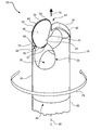
- FIG. 1 is a perspective view of an exemplary drill bit according to at least one embodiment.
- FIG. 2 is a perspective view of an exemplary cutting element according to at least one embodiment.
- FIG. 3A is a perspective view of an exemplary cutting element according to at least one embodiment.
- FIG. 3B is a front view of the exemplary cutting element illustrated in FIG. 3A .
- FIG. 4 is a perspective view of an exemplary bit body according to at least one embodiment.
- FIG. 5A is a perspective view of a portion of the exemplary bit body illustrated in FIG. 4 according to at least one embodiment.
- FIG. 5B is a partial cross-sectional view of a portion of the exemplary bit body illustrated in FIG. 4 .
- FIG. 6 is a perspective view of a portion of an exemplary drill bit that includes a cutting element coupled to the bit body illustrated in FIG. 5A according to at least one embodiment.
- FIG. 7 is a front view of the portion of the exemplary drill bit illustrated in FIG. 6 .
- FIG. 8 is a perspective view of an exemplary drilling apparatus according to at least one embodiment.
- FIG. 9 is a perspective view of an exemplary bit body according to at least one embodiment.
- FIG. 10 is a perspective view of an exemplary drill bit that includes the exemplary bit body illustrated in FIG. 9 according to at least one embodiment.
- FIG. 11 is a perspective view of an exemplary bit body according to at least one embodiment.
- FIG. 12 is a perspective view of an exemplary drill bit that includes the exemplary bit body illustrated in FIG. 11 according to at least one embodiment.
- a drill bit such as a roof-bolt drill bit
- a drilling apparatus configured to rotate the drill bit relative to a subterranean formation.
- Cutting elements for cutting the subterranean formation may be mounted to a bit body of the drill bit.
- the word “cutting,” as used in this specification and claims, refers broadly to machining processes, drilling processes, boring processes, or any other material removal process.
- FIG. 1 is a perspective view of a portion of an exemplary drill bit 20 according to at least one embodiment.
- Drill bit 20 may represent any type or form of earth-boring or drilling tool, including, for example, a roof-bolt drill bit.
- Drill bit 20 may be formed of any material or combination of materials, such as steel or molded tungsten carbide, without limitation.
- drill bit 20 may comprise a bit body 22 having a forward end 24 , a rearward end 26 , and a rotational axis 28 .
- At least one cutting element 34 may be coupled to bit body 22 .
- a plurality of cutting elements 34 may be coupled to forward end 24 of bit body 22 .
- Cutting elements 34 may each be mounted and secured in corresponding coupling pockets 36 defined in bit body 22 .
- the at least one cutting element may be positioned with a back rake angle of between approximately 5° and approximately 45° and a side rake angle of between approximately 0° and approximately 20°.
- two cutting elements 34 may be positioned on bit body 22 circumferentially substantially 180° apart with substantially the same back rake angles and substantially the same side rake angles.
- an internal passage 30 may be defined within bit body 22 .
- Internal passage 30 may extend from a rearward opening defined in rearward end 26 of bit body 22 to at least one side opening 32 defined in a side portion of bit body 22 .
- drill bit 20 may be configured for use in dry-drilling environments where cutting debris is removed from a borehole by applying a vacuum to internal passage 30 .
- a vacuum applied to internal passage 30 may generate suction near side opening 32 , thereby drawing cutting debris away from the borehole and through side opening 32 .
- a vacuum applied to internal passage 30 may also facilitate cooling of cutting elements 34 and/or other portions of drill bit 20 through convective heat transfer as air and debris are drawn over and around cutting elements 34 .
- one side opening 32 may be defined in bit body 22 for each cutting element 34 .
- two side openings 32 may be defined in bit body 22 , with the two side openings 32 corresponding to the two respective cutting elements 34 illustrated in FIG. 1 .
- a bit body of a drill bit may not include a debris opening for removing cutting debris (e.g., drill bit 220 illustrated in FIG. 11 ).
- FIGS. 2 and 3 illustrate exemplary cutting elements according to various embodiments.
- FIG. 2 is a perspective view of a cutting element 34 that may be coupled to exemplary bit body 22 in FIG. 1 .
- cutting element 34 may comprise a layer or table 46 affixed to or formed upon a substrate 47 .
- Table 46 may be formed of any material or combination of materials suitable for cutting subterranean formations, including, for example, a superhard or superabrasive material such as polycrystalline diamond (PCD).
- PCD polycrystalline diamond
- Substrate 47 may comprise any material or combination of materials capable of adequately supporting a superabrasive material during drilling of a subterranean formation, including, for example, cemented tungsten carbide.
- cutting element 34 may comprise a superhard PCD table 46 comprising polycrystalline diamond bonded to a substrate 47 comprising cobalt-cemented tungsten carbide.
- a catalyst material e.g., cobalt or nickel
- a catalyst material may be removed from at least a portion of PCD table 46 using any suitable technique, such as, for example, acid leaching.
- the PCD table 46 may be fabricated by subjecting a plurality of diamond particles to an HPHT sintering process in the presence of a metal-solvent catalyst (e.g., cobalt, nickel, iron, or alloys thereof) to facilitate intergrowth between the diamond particles and form a PCD body comprised of bonded diamond grains that exhibit diamond-to-diamond bonding therebetween.
- a metal-solvent catalyst e.g., cobalt, nickel, iron, or alloys thereof
- the metal-solvent catalyst may be mixed with the diamond particles, infiltrated from a metal-solvent catalyst foil or powder adjacent to the diamond particles, infiltrated from a metal-solvent catalyst present in a cemented carbide substrate, or combinations of the foregoing.
- the temperature of the HPHT process may be at least about 1000° C.
- the pressure of the HPHT process may be at least 4.0 GPa (e.g., about 5.0 GPa to about 10.0 GPa, about 5.0 GPa to about 8.0 GPa, or about 7.5 GPa to about 9.0 GPa) for a time sufficient to bond the diamond particles to one another (e.g., via sp 3 bonding).
- the bonded diamond grains (e.g., sp 3 -bonded diamond grains), so-formed by HPHT sintering the diamond particles, define interstitial regions with the metal-solvent catalyst disposed within the interstitial regions.
- the diamond particles may exhibit a selected diamond particle size distribution.
- the as-sintered PCD body may be leached by immersion in an acid, such as aqua regia, nitric acid, hydrofluoric acid, or subjected to another suitable process to remove at least a portion of the metal-solvent catalyst from the interstitial regions of the PCD body and form the PCD table 46 .
- the as-sintered PCD body may be immersed in the acid for about 2 to about 7 days (e.g., about 3, 5, or 7 days) or for a few weeks (e.g., about 4 weeks) depending on the process employed. Even after leaching, a residual, detectable amount of the metal-solvent catalyst may be present in the at least partially leached PCD table 102 .
- the infiltrated metal-solvent catalyst when the metal-solvent catalyst is infiltrated into the diamond particles from a cemented tungsten carbide substrate including tungsten carbide particles cemented with a metal-solvent catalyst (e.g., cobalt, nickel, iron, or alloys thereof), the infiltrated metal-solvent catalyst may carry tungsten and/or tungsten carbide therewith and the as-sintered PCD body may include such tungsten and/or tungsten carbide therein disposed interstitially between the bonded diamond grains.
- the tungsten and/or tungsten carbide may be at least partially removed by the selected leaching process or may be relatively unaffected by the selected leaching process.
- the plurality of diamond particles sintered to form the PCD table 46 may exhibit one or more selected sizes.
- the one or more selected sizes may be determined, for example, by passing the diamond particles through one or more sizing sieves or by any other method.
- the plurality of diamond particles may include a relatively larger size and at least one relatively smaller size.
- the phrases “relatively larger” and “relatively smaller” refer to particle sizes determined by any suitable method, which differ by at least a factor of two (e.g., 40 ⁇ m and 20 ⁇ m).
- the plurality of diamond particles may include a portion exhibiting a relatively larger size (e.g., 100 ⁇ m, 90 ⁇ m, 80 ⁇ m, 70 ⁇ m, 60 ⁇ m, 50 ⁇ m, 40 ⁇ m, 30 ⁇ m, 20 ⁇ m, 15 ⁇ m, 12 ⁇ m, 10 ⁇ m, 8 ⁇ m) and another portion exhibiting at least one relatively smaller size (e.g., 30 ⁇ m, 20 ⁇ m, 10 ⁇ m, 15 ⁇ m, 12 ⁇ m, 10 ⁇ m, 8 ⁇ m, 4 ⁇ m, 2 ⁇ m, 1 ⁇ m, 0.5 ⁇ m, less than 0.5 ⁇ m, 0.1 ⁇ m, less than 0.1 ⁇ m).
- a relatively larger size e.g., 100 ⁇ m, 90 ⁇ m, 80 ⁇ m, 70 ⁇ m, 60 ⁇ m, 50 ⁇ m, 40 ⁇ m, 30 ⁇ m, 20 ⁇ m, 15 ⁇ m, 12 ⁇ m, 10
- the plurality of diamond particles may include a portion exhibiting a relatively larger size between about 40 ⁇ m and about 15 ⁇ m and another portion exhibiting a relatively smaller size between about 12 ⁇ m and 2 ⁇ m.
- the plurality of diamond particles may also include three or more different sizes (e.g., one relatively larger size and two or more relatively smaller sizes) without limitation.
- cutting element 34 may also comprise a cutting face 48 formed by table 46 , an element side surface 50 formed by table 46 and substrate 47 , and an element back surface 62 formed by substrate 47 .
- Cutting face 48 , element side surface 50 , and element back surface 62 may be formed in any suitable shape, without limitation.
- cutting face 48 may have a partially arcuate periphery.
- cutting face 48 may be substantially planar and element side surface 50 may comprise a partial-cylindrical and/or otherwise arcuate surface that is optionally perpendicular to cutting face 48 .
- cutting face 48 may have a substantially semi-circular or partial-circular periphery that includes one or more rounded corner portions.
- Element back surface 62 may be, in some embodiments, substantially parallel to cutting face 48 .
- cutting element 34 may comprise a chamfer 52 formed on the superabrasive table along at least a portion of a periphery of table 46 between cutting face 48 and element side surface 50 .
- Table 46 may also include any other suitable surface shape between cutting face 48 and element side surface 50 , including, without limitation, an arcuate surface (e.g., a radius), a sharp edge, multiple chamfers/radii, a honed edge, and/or combinations of the foregoing.
- Chamfer 52 may be configured to contact and/or cut a subterranean formation as drill bit 20 is rotated relative to the formation (as will be described in greater detail below in connection with FIG. 7 ).
- cutting edge refers to an edge portion of cutting element 34 that is exposed to and/or in contact with a formation during drilling.
- cutting element 34 may comprise one or more cutting edges, such as an edge 64 and/or or an edge 66 .
- Edge 64 and/or edge 66 may be formed adjacent chamfer 52 and may be configured to be exposed to and/or in contact with a formation during drilling.
- edge 64 may be formed at an intersection between cutting face 48 and chamfer 52 and edge 66 may be formed at an intersection between element side surface 50 and chamfer 52 .
- Element side surface 50 of cutting element 34 may comprise one or more surface portions.
- element side surface 50 may include a first element side surface portion 54 , a second element side surface portion 56 , and a third element side surface portion 57 extending between first element side surface portion 54 and second element side surface portion 56 .
- at least one of first element side surface portion 54 and second element side surface portion 56 may comprise a substantially planar surface.
- both first element side surface portion 54 and second element side surface portion 56 comprise substantially planar surfaces extending in nonparallel directions relative to each other.
- at least one of first element side surface portion 54 and/or second element side surface portion 56 may be nonplanar (e.g., arcuate second element side surface portion 156 illustrated in FIGS. 3A and 3B ).
- Third element side surface portion 57 may comprise any suitable shape and configuration.
- third element side surface portion 57 may comprise a substantially planar surface, as shown in FIG. 2 .
- third element side surface portion 57 may be nonplanar (e.g., arcuate third element side surface portion 157 illustrated in FIGS. 3A and 3B ).
- Two or more of first element side surface portion 54 , second element side surface portion 56 , and third element side surface portion 57 may be configured to contact one or more corresponding surface portions defining coupling pocket 36 of bit body 22 (as will be described in greater detail below in connection with FIGS. 6 and 7 ).
- element side surface 50 may also comprise an arcuate side surface portion 60 extending along a peripheral portion of cutting element 34 from first element side surface portion 54 to second element side surface portion 56 .
- arcuate side surface portion 60 may be formed adjacent chamfer 52 .
- edge 66 may be formed at an intersection between arcuate side surface portion 60 and chamfer 52 .
- At least a portion of arcuate side surface portion 60 may be configured to face generally outward from cutting element 34 (as will be described in greater detail below in connection with FIGS. 6 and 7 ).
- FIGS. 3A and 3B show an exemplary cutting element 134 .
- cutting element 134 may comprise a table 146 affixed to and/or formed upon a substrate 147 .
- Cutting element 134 may comprise a cutting face 148 formed by table 146 , an element side surface 150 formed by table 146 and substrate 147 , and an element back surface 162 formed by substrate 147 .
- Cutting element 134 may also comprise a chamfer 152 formed on the superabrasive table along at least a portion of a periphery of table 146 between cutting face 148 and element side surface 150 .
- An edge 164 and/or an edge 166 may be formed adjacent chamfer 152 and may be configured to be at least partially exposed to and/or at least partially in contact with a formation during drilling.
- Element side surface 150 of cutting element 134 may include a first element side surface portion 154 , a second element side surface portion 156 , and a third element side surface portion 157 extending between first element side surface portion 154 and second element side surface portion 156 .
- Element side surface 150 may also include a fourth element side surface portion 158 and a fifth element side surface portion 159 extending between first element side surface portion 154 and fourth element side surface portion 158 .
- Element side surface 150 may also comprise an arcuate side surface portion 160 extending around a peripheral portion of cutting element 134 from second element side surface portion 156 to fourth element side surface portion 158 .
- first element side surface portion 154 may comprise a substantially planar surface.
- first element side surface portion 154 may comprise a substantially planar surface
- second element side surface portion 156 and fourth element side surface portion 158 may each comprise a nonplanar surface portion.
- second element side surface portion 156 and fourth element side surface portion 158 may be arcuate.
- Third element side surface portion 157 and fifth element side surface portion 159 may each comprise any suitable shape and configuration.
- third element side surface portion 157 and/or fifth element side surface portion 159 may each be nonplanar.
- third element side surface portion 157 and/or fifth element side surface portion 159 may be arcuate.
- Two or more of first element side surface portion 154 , second element side surface portion 156 , third element side surface portion 157 , fourth element side surface portion 158 , and/or fifth element side surface portion 159 may be configured to contact one or more corresponding surface portions of a coupling pocket of a bit body (as will be described in greater detail below in connection with FIG. 9 ).
- FIGS. 4, 5A, and 5B illustrate the exemplary bit body 22 shown in FIG. 1 .
- FIG. 4 is a perspective view of bit body 22
- FIG. 5A is a perspective view of a portion of bit body 22 that includes detail of coupling pocket 36
- FIG. 5B is a partial cross-sectional view of a portion of bit body 22 .
- at least one coupling pocket 36 may be defined in bit body 22 at or near forward end 24 .
- Coupling pockets 36 may be formed to couple cutting elements 34 to bit body 22 .
- At least a portion of each coupling pocket 36 may be configured to abut at least a portion of a corresponding cutting element 34 (as will be described in greater detail below in connection with FIGS.
- coupling pocket 36 may extend between forward end 24 and side opening 32 defined in bit body 22 .
- Coupling pocket 36 may be formed in bit body 22 using any suitable technique, such as, for example, milling and/or molding, without limitation.
- coupling pocket 36 may be machined in bit body 22 using an end mill to remove material from bit body 22 .
- a continuous milling pass by a single end mill may be used to form a pocket back surface 68 , a first pocket side surface 70 , a second pocket side surface 72 , and a pocket transition region 74 in bit body 22 .
- coupling pocket 36 may be defined in cutting element 34 by pocket back surface 68 and one or more side surface portions.
- coupling pocket may be defined by first pocket side surface 70 and second pocket side surface 72 .
- Coupling pocket 36 may also be defined by pocket transition region 74 extending between first pocket side surface 70 and second pocket side surface 72 .
- Pocket back surface 68 , first pocket side surface 70 , second pocket side surface 72 , and pocket transition region 74 may comprise any suitable shape and configuration for abutting at least a portion of a cutting element 34 mounted to bit body 22 .
- pocket back surface 68 may comprise a surface that is complementary to a back surface of cutting element 34 (e.g., element back surface 62 illustrated in FIG. 2 ).
- pocket back surface 68 may comprise a substantially planar surface configured to support and/or abut the corresponding element back surface 62 of cutting element 34 .
- First pocket side surface 70 , second pocket side surface 72 , and/or pocket transition region 74 may extend outward from pocket back surface 68 . For example, as illustrated in FIG.
- first pocket side surface 70 , second pocket side surface 72 , and/or pocket transition region 74 may extend from pocket back surface 68 at, respectively, an angle ⁇ 1 , an angle ⁇ 2 , and/or an angle ⁇ 3 of between approximately 60° and approximately 120°.
- first pocket side surface 70 , second pocket side surface 72 , and/or pocket transition region 74 may extend from pocket back surface 68 at, respectively, an angle ⁇ 1 , an angle ⁇ 2 , and/or an angle ⁇ 3 of approximately 90°.
- First pocket side surface 70 and/or second pocket side surface 72 may comprise a substantially planar surface. First pocket side surface 70 and second pocket side surface 72 may extend in any suitable direction relative to each other and relative to bit body 22 . In at least one embodiment, first pocket side surface 70 and/or second pocket side surface 72 may each extend at a respective angle that is nonparallel to rotational axis 28 . First pocket side surface 70 may also be nonparallel to second pocket side surface 72 . For example, as illustrated in FIG. 5A , first pocket side surface 70 may extend at an angle ⁇ of between approximately 45° and approximately 135° relative to second pocket side surface 72 .
- FIGS. 6 and 7 show a portion of the exemplary drill bit 20 illustrated in FIG. 1 .
- cutting element 34 may be at least partially disposed in coupling pocket 36 . At least a portion of cutting element 34 may be adjacent to one or more surface portions of bit body 22 defining coupling pocket 36 . In some embodiments, portions of cutting element 34 may directly contact adjacent portions of bit body 22 . In additional embodiments, a material, such as a brazing alloy, may be disposed between at least a portion of cutting element 34 and at least a portion of bit body 22 .
- Cutting element 34 may be coupled to bit body 22 using any suitable technique.
- each cutting element 34 may be brazed, welded, soldered, threadedly coupled, and/or otherwise adhered and/or fastened to bit body 22 .
- element back surface 62 of cutting element 34 may be brazed to pocket back surface 68 of bit body 22 .
- Any suitable brazing and/or or welding material and/or technique may be used to attach cutting element 34 to bit body 22 .
- cutting element 34 may be brazed to bit body 22 using a suitable braze material, such as, for example, an alloy comprising silver, tin, zinc, copper, palladium, nickel, and/or any other suitable metal compound.
- cutting element 34 may be press fit or mechanically attached to bit body 22 .
- cutting element 34 may be disposed in and affixed to coupling pocket 36 such that at least a portion of element back surface 62 of cutting element 34 is positioned adjacent to and/or abutting pocket back surface 68 of bit body 22 .
- Element back surface 62 may be substantially parallel to pocket back surface 68 .
- at least a portion of element side surface 50 may be positioned adjacent to and/or abutting at least a portion bit body 22 .
- first element side surface portion 54 may be positioned adjacent to and/or abutting first pocket side surface 70 .
- first element side surface portion 54 may extend in a direction substantially parallel to first pocket side surface 70 when cutting element 34 is coupled to bit body 22 .
- second element side surface portion 56 may be positioned adjacent to and/or abutting second pocket side surface 72 such that second element side surface portion 56 extends in a direction substantially parallel to second pocket side surface 72 when cutting element 34 is coupled to bit body 22 .
- Coupling pocket 36 may facilitate coupling of cutting element 34 to bit body 22 in a specified orientation.
- first element side surface portion 54 abuts first pocket side surface 70 and second element side surface portion 56 abuts second pocket side surface 72
- at least a portion of arcuate side surface portion 60 , chamfer 52 , edge 64 , and/or edge 66 may be selectively positioned relative to bit body 22 .
- cutting element 34 may be positioned in coupling pocket 36 so that selected portions of cutting element 34 configured for contacting and cutting a subterranean formation, such as chamfer 52 , edge 64 , edge 66 , arcuate side surface portion 60 , and/or at least a portion of cutting face 48 , are exposed to the subterranean formation during drilling. Additionally, portions of bit body 22 defining coupling pocket 36 may restrict one or more degrees of freedom of movement of cutting element 34 relative to bit body 22 during drilling (as will be described in greater detail below in connection with FIG. 8 ).
- third element side surface portion 57 may not be congruent with or conform to a side surface portion of coupling pocket 36 , such as pocket transition region 74 .
- third element side surface portion 57 may comprise a substantially planar surface extending between first element side surface portion 54 and second element side surface portion 56 in such a manner that third element side surface portion 57 does not conform to pocket transition region 74 , which is arcuate.
- third element side surface portion 57 may comprise a nonplanar surface portion that does not conform to pocket transition region 74 when cutting element 34 is positioned in coupling pocket 36 . Accordingly, a gap (e.g., varying in thickness) may be present between third element side surface portion 57 and pocket transition region 74 .
- both first element side surface portion 54 and second element side surface portion 56 of cutting element 34 may abut portions of bit body 22 defining coupling pocket 36 , such as first pocket side surface 70 and second pocket side surface 72 .
- third element side surface portion 57 may not contact a portion of bit body 22 so as to allow first element side surface portion 54 and/or second element side surface portion 56 to closely abut corresponding portions of bit body 22 , such as first pocket side surface 70 and/or second pocket side surface 72 . Accordingly, cutting element 34 may be securely positioned in coupling pocket 36 .
- FIG. 8 is a perspective view of a portion of an exemplary drilling apparatus 80 that includes the exemplary drill bit 20 illustrated in FIG. 1 according to at least one embodiment.
- Drilling apparatus 80 may comprise drill bit 20 coupled to a drill steel 82 .
- drill bit 20 may be rotated about rotational axis 28 in rotational direction 78 during a drilling operation, such as a subterranean drilling operation.
- drill steel 82 may rotate drill bit 20 in rotational direction 78 during drilling of a borehole.
- drill steel 82 may comprise any suitable type of drilling rod or other suitable connection member configured to connect drill bit 20 to a drilling apparatus, without limitation.
- drill steel 82 may comprise a substantially elongated shaft (e.g., a cylindrical shaft) having coupling surfaces corresponding to surfaces defined within drill bit 20 .
- drill steel 82 may comprise a hexagonal and/or threaded periphery corresponding to a hexagonal and/or threaded interior surface defined within drill bit 20 .
- drill steel 82 may comprise a pin connector corresponding to a pin hole and/or a recess defined within drill bit 20 .
- forces and/or torque may be applied by a drilling motor to drill bit 20 via drill steel 82 , causing drill bit 20 to be forced against a subterranean formation in both rotational direction 78 and forward direction 76 .
- cutting elements 34 may contact and cut into the subterranean formation, removing rock material from the formation in the form of rock cuttings and/or other debris. As shown in FIG.
- each cutting element 34 may be positioned in a corresponding coupling pocket 36 so that portions of cutting element 34 configured for contacting and cutting a subterranean formation, such as chamfer 52 , edges adjacent chamfer 52 (e.g., edge 64 and edge 66 illustrated in FIG. 2 ), arcuate side surface portion 60 , and/or at least a portion of cutting face 48 , are exposed to the subterranean formation during drilling.
- cutting debris removed by cutting elements 34 may be drawn through internal passage 30 defined in bit body 22 by a vacuum applied to drill bit 20 .
- drill steel 82 may comprise a hollow rod and a vacuum may be applied to a rearward end of drill steel 82 by a vacuum source. Cutting debris may be drawn by the vacuum through drill bit 20 and drill steel 82 toward the vacuum source.
- each cutting element 34 may act on each cutting element 34 in generally sideward directions, rearward directions, radially inward directions, other directions, and/or combinations thereof relative to drill bit 20 .
- Each cutting element 34 may be secured to bit body 22 (e.g., by brazing) so as to resist the various forces and stresses that cutting element 34 is subjected to during drilling, preventing separation of cutting elements 34 from bit body 22 .
- second pocket side surface 72 of bit body 22 may prevent movement of cutting element 34 in a generally axially rearward direction opposite axially forward direction 76 .
- First pocket side surface 70 may prevent movement of cutting element 34 in a generally sideward and/or generally radially inward direction relative to bit body 22 .
- first pocket side surface 70 and/or second pocket side surface 72 may prevent cutting element 34 from rotating within coupling pocket 36 .
- cutting element 34 when cutting element 34 is positioned within coupling pocket 36 such that first element side surface portion 54 abuts first pocket side surface 70 and/or second element side surface portion 56 abuts second pocket side surface 72 , cutting element 34 may be prevented from rotating within coupling pocket 36 about an axis, such as an axis that is generally perpendicular to pocket back surface 68 of bit body 22 .
- Forces applied to cutting element 34 during drilling may be generated such that they are directed generally toward first pocket side surface 70 and/or second pocket side surface 72 , which may further constrain cutting element 34 in coupling pocket 36 and may prevent rotational movement of cutting element 34 relative to coupling pocket 36 .
- cutting element 34 may be secured to bit body 22 (e.g., by brazing) so as to resist various forces and stresses that cutting element 34 is subjected to during drilling, preventing separation of cutting element 34 from bit body 22 .
- FIGS. 9-12 show exemplary drill bits and bit bodies according to various embodiments.
- FIG. 9 is a perspective view of an exemplary bit body 122 according to at least one embodiment.
- Bit body 122 may have a forward end 124 , a rearward end 126 , and a rotational axis 128 .
- an internal passage 130 may be defined within bit body 122 .
- Internal passage 130 may extend from a rearward opening defined in rearward end 126 of bit body 122 to at least one side opening 132 defined in a side portion of bit body 122 .
- At least one coupling pocket 136 may be defined in bit body 122 at or near forward end 124 . In some embodiments, coupling pocket 136 may extend between forward end 124 and side opening 132 defined in bit body 122 .
- each coupling pocket 136 may be defined by a pocket back surface 168 and one or more side surface portions.
- coupling pocket 136 may be defined by a first pocket side surface 170 and a second pocket side surface 172 .
- First pocket side surface 170 and/or second pocket side surface 172 may comprise a substantially planar surface.
- First pocket side surface 170 and second pocket side surface 172 may extend in any suitable direction relative to each other and relative to bit body 122 .
- first pocket side surface 170 may be nonparallel to second pocket side surface 172 .
- a gap 184 may be defined between first pocket side surface 170 and second pocket side surface 172 .
- gap 184 may extend between first pocket side surface 170 and second pocket side surface 172 at a region of bit body 122 where coupling pocket 136 intersects side opening 132 .
- gap 184 may be formed at a location other than a region intersecting side opening 132 .
- FIG. 10 is a perspective view of an exemplary drill bit 120 comprising at least one cutting element 134 that is coupled to the bit body 122 illustrated in FIG. 9 according to at least one embodiment.
- at least one cutting element 134 e.g., cutting element 134 illustrated in FIGS. 3A and 3B
- At least a portion of cutting element 134 may be adjacent to and/or abutting one or more surface portions of bit body 122 defining coupling pocket 136 .
- cutting element 134 may be disposed in and affixed to coupling pocket 136 such that at least a portion of an element back surface of cutting element 134 (e.g., element back surface 162 illustrated in FIG. 3A ) is positioned adjacent to and/or abutting a back surface defining coupling pocket 136 (e.g., pocket back surface 168 illustrated in FIG. 9 ).
- Element back surface 162 may be substantially parallel to pocket back surface 168 .
- at least a portion of element side surface 150 may be positioned adjacent to and/or abutting at least a portion bit body 122 .
- first element side surface portion 154 may be positioned adjacent to and/or abutting first pocket side surface 170 .
- first element side surface portion 154 may extend in a direction substantially parallel to first pocket side surface 170 when cutting element 134 is coupled to bit body 122 .
- second element side surface portion 156 may be positioned adjacent to and/or abutting second pocket side surface 172 such that second pocket side surface 172 extends in a direction substantially tangential to a portion of second element side surface portion 156 contacting second pocket side surface 172 when cutting element 134 is coupled to bit body 122 .
- second element side surface portion 156 may comprise an arcuate surface portion and second pocket side surface 172 may comprise a substantially planar surface.
- Cutting element 134 may be positioned in and affixed to coupling pocket 136 so that portions of cutting element 134 configured for contacting and cutting a subterranean formation, such as chamfer 152 , edges adjacent chamfer 152 (e.g., edge 164 and/or edge 166 illustrated in FIGS. 3A and 3B ), arcuate side surface portion 160 , and/or at least a portion of cutting face 148 , are exposed to the subterranean formation during drilling. Additionally, portions of bit body 122 defining coupling pocket 136 may restrict one or more degrees of freedom of movement of cutting element 134 relative to bit body 122 during drilling.
- At least a portion of cutting element 134 may extend through gap 184 defined between first pocket side surface 170 and second pocket side surface 172 .
- a portion of cutting element 134 that includes third element side surface portion 157 may be disposed outside of coupling pocket 136 within and/or overlapping a portion of side opening 132 .
- third element side surface portion 157 of cutting element 134 may not contact coupling pocket 136 , and therefore, both first element side surface portion 154 and second element side surface portion 156 of cutting element 134 may be disposed closely abutting corresponding portions of bit body 122 , such as first pocket side surface 170 and second pocket side surface 172 .
- a portion of cutting element 134 extending between first element side surface portion 154 and second element side surface portion 156 may not contact a portion of bit body 122 so as to prevent first element side surface portion 154 and/or second element side surface portion 156 from closely abutting portions of bit body 122 , such as first pocket side surface 170 and/or second pocket side surface 172 .
- cutting element 134 may be securely positioned in coupling pocket 136 by brazing, for example.
- cutting element 134 may be secured to bit body 122 (e.g., by brazing) so as to resist the various forces and stresses that cutting element 134 is subjected to during drilling, preventing separation of cutting element 134 from bit body 122 .
- second pocket side surface 172 of bit body 122 in combination with first side pocket surface 170 , may prevent movement of cutting element 134 in an axially rearward direction.
- First pocket side surface 170 may prevent movement of cutting element 134 in a generally sideward and/or radially inward direction relative to bit body 122 .
- first pocket side surface 170 and/or second pocket side surface 172 may prevent cutting element 134 from rotating within coupling pocket 136 .
- cutting element 134 when cutting element 134 is positioned within coupling pocket 136 such that first element side surface portion 154 abuts first pocket side surface 170 and/or second element side surface portion 156 abuts second pocket side surface 172 , cutting element 134 may be prevented from rotating within coupling pocket 136 about an axis, such as an axis that is generally perpendicular to pocket back surface 168 of bit body 122 .
- Forces applied to cutting element 134 during drilling may be directed such that cutting element 134 is supported by first pocket side surface 170 and/or second pocket side surface 172 , which may further constrain cutting element 134 in coupling pocket 136 and may prevent rotational movement of cutting element 134 relative to coupling pocket 136 . Accordingly, cutting element 134 may be secured to bit body 122 (e.g., by brazing) so as to resist various forces and stresses that cutting element 134 is subjected to during drilling, preventing separation of cutting element 134 from bit body 122 .
- FIG. 11 is a perspective view of an exemplary bit body 222
- FIG. 12 is a perspective view of an exemplary drill bit 220 that includes bit body 222 according to at least one embodiment.
- Drill bit 220 may be configured for use in wet-drilling environments where drilling fluids, such as drilling mud or water, are used to cool drill bit 220 and flush debris away from drill bit 220 and out of a borehole during drilling.
- drilling fluids such as drilling mud or water
- one or more ports 282 for dispensing drilling fluids during cutting may be defined in forward and/or side portions of bit body 222 .
- Drilling fluids may be conveyed to ports 282 through one or more internal passages extending through bit body 222 .
- Bit body 222 may have a forward end 224 , a rearward end 226 , and a rotational axis 228 .
- At least one coupling pocket 236 may be defined in bit body 222 at or near forward end 224 .
- Each coupling pocket 236 may be defined by a pocket back surface 268 and one or more side surface portions.
- coupling pocket 236 may be defined by a first pocket side surface 270 and a second pocket side surface 272 .
- First pocket side surface 270 and/or second pocket side surface 272 may comprise a substantially planar surface.
- First pocket side surface 270 and second pocket side surface 272 may extend in any suitable direction relative to each other and relative to bit body 222 .
- first pocket side surface 270 may be nonparallel to second pocket side surface 272 .
- first pocket side surface 270 and second pocket side surface 272 may be perpendicular to one another.
- Coupling pocket 236 may also be defined by a pocket transition region 274 extending between first pocket side surface 270 and second pocket side surface 272 .
- At least one cutting element 234 may be at least partially disposed in corresponding coupling pockets 236 .
- Each cutting element 234 may comprise a cutting face 248 , an element side surface 250 , and an element back surface (e.g., element back surface 162 illustrated in FIG. 3A ).
- Cutting element 234 may also comprise a chamfer 252 formed on the superabrasive table along at least a portion of a periphery of cutting element 234 between cutting face 248 and element side surface 250 .
- Element side surface 250 of cutting element 234 may include a first element side surface portion 254 , a second element side surface portion 256 , and a third element side surface portion 257 extending between first element side surface portion 254 and second element side surface portion 256 .
- Element side surface 250 may also comprise an arcuate side surface portion 260 extending around a peripheral portion of cutting element 234 from first element side surface portion 254 to second element side surface portion 256 .
- At least one of first element side surface portion 254 and second element side surface portion 256 may comprise a substantially planar surface.
- first element side surface portion 254 may comprise a substantially planar surface and second element side surface portion 256 may comprise a nonplanar surface portion.
- second element side surface portion 256 may comprise an arcuate surface portion configured to correspond to and/or abut second pocket side surface 272 of bit body 222 .
- each cutting element 234 may be adjacent to one or more surface portions of bit body 222 defining coupling pocket 236 . In some embodiments, portions of cutting element 234 may directly contact adjacent portions of bit body 222 . In additional embodiments, a material, such as a brazing alloy, may be disposed between at least a portion of cutting element 234 and at least a portion of bit body 222 . Cutting element 234 may be disposed in and affixed to coupling pocket 236 such that at least a portion of a back surface of cutting element 234 (e.g., element back surface 162 illustrated in FIG. 3A ) is positioned adjacent to and/or abutting pocket back surface 268 of bit body 222 . Additionally, at least a portion of element side surface 250 may be positioned adjacent to and/or abutting at least a portion bit body 222 .
- a back surface of cutting element 234 e.g., element back surface 162 illustrated in FIG. 3A
- at least a portion of element side surface 250 may be
- first element side surface portion 254 may be positioned adjacent to and/or abutting first pocket side surface 270 .
- First element side surface portion 254 may extend in a direction substantially parallel to first pocket side surface 270 when cutting element 234 is coupled to bit body 222 .
- second element side surface portion 256 may be positioned adjacent to and/or abutting second pocket side surface 272 such that second pocket side surface 272 extends in a direction substantially tangential to a portion of second element side surface portion 256 contacting second pocket side surface 272 when cutting element 234 is coupled to bit body 222 .
- second element side surface portion 256 may comprise an arcuate surface portion and second pocket side surface 272 may comprise a substantially planar surface.
- Third element side surface portion 257 may comprise any suitable shape and configuration. In some embodiments, third element side surface portion 257 may be nonplanar. For example, third element side surface portion 257 may be arcuate.
- Cutting element 234 may be positioned in coupling pocket 236 so that portions of cutting element 234 configured for contacting and cutting a subterranean formation, such as chamfer 252 , edges adjacent chamfer 252 (e.g., edge 164 and/or edge 166 illustrated in FIGS. 3A and 3B ), arcuate side surface portion 260 , and/or at least a portion of cutting face 248 , are exposed to the subterranean formation during drilling. Additionally, portions of bit body 222 defining coupling pocket 236 may restrict one or more degrees of freedom of movement of cutting element 234 relative to bit body 222 during drilling.
- third element side surface portion 257 may also optionally abut a portion of coupling pocket 236 , such as pocket transition region 274 .
- cutting element 234 may be secured to bit body 222 (e.g., by brazing) so as to resist the various forces and stresses that cutting element 234 is subjected to during drilling, preventing separation of cutting element 234 from bit body 222 .
- second pocket side surface 272 of bit body 222 may prevent movement of cutting element 234 in an axially rearward direction.
- First pocket side surface 270 of bit body 222 may prevent movement of cutting element 234 in a generally sideward and/or radially inward direction relative to bit body 222 .
- first pocket side surface 270 and/or second pocket side surface 272 may prevent cutting element 234 from rotating within coupling pocket 236 .
- cutting element 234 when cutting element 234 is positioned within coupling pocket 236 such that first element side surface portion 254 abuts first pocket side surface 270 and/or second element side surface portion 256 abuts second pocket side surface 272 , cutting element 234 may be prevented from rotating within coupling pocket 236 about an axis, such as an axis that is generally perpendicular to pocket back surface 268 of bit body 222 .
- Forces applied to cutting element 234 during drilling may be directed such that cutting element 234 is supported by first pocket side surface 270 and/or second pocket side surface 272 , which may further constrain cutting element 234 in coupling pocket 236 and may prevent rotational movement of cutting element 234 relative to coupling pocket 236 . Accordingly, cutting element 234 may be secured to bit body 222 (e.g., by brazing) so as to resist various forces and stresses that cutting element 234 is subjected to during drilling, preventing separation of cutting element 234 from bit body 222 .
Landscapes
- Engineering & Computer Science (AREA)
- Life Sciences & Earth Sciences (AREA)
- Mining & Mineral Resources (AREA)
- Geology (AREA)
- Mechanical Engineering (AREA)
- Physics & Mathematics (AREA)
- Environmental & Geological Engineering (AREA)
- Fluid Mechanics (AREA)
- General Life Sciences & Earth Sciences (AREA)
- Geochemistry & Mineralogy (AREA)
- Chemical & Material Sciences (AREA)
- Crystallography & Structural Chemistry (AREA)
- Earth Drilling (AREA)
- Drilling Tools (AREA)
Abstract
Description
Claims (20)
Priority Applications (2)
| Application Number | Priority Date | Filing Date | Title |
|---|---|---|---|
| US14/667,410 US9903164B2 (en) | 2011-05-04 | 2015-03-24 | Drill bits and drilling apparatuses including the same |
| US15/878,391 US10400516B2 (en) | 2011-05-04 | 2018-01-23 | Drill bits and methods for manufacturing the same |
Applications Claiming Priority (2)
| Application Number | Priority Date | Filing Date | Title |
|---|---|---|---|
| US13/100,512 US9010464B2 (en) | 2011-05-04 | 2011-05-04 | Drill bits and drilling apparatuses including the same |
| US14/667,410 US9903164B2 (en) | 2011-05-04 | 2015-03-24 | Drill bits and drilling apparatuses including the same |
Related Parent Applications (1)
| Application Number | Title | Priority Date | Filing Date |
|---|---|---|---|
| US13/100,512 Continuation US9010464B2 (en) | 2011-05-04 | 2011-05-04 | Drill bits and drilling apparatuses including the same |
Related Child Applications (1)
| Application Number | Title | Priority Date | Filing Date |
|---|---|---|---|
| US15/878,391 Continuation US10400516B2 (en) | 2011-05-04 | 2018-01-23 | Drill bits and methods for manufacturing the same |
Publications (2)
| Publication Number | Publication Date |
|---|---|
| US20150197990A1 US20150197990A1 (en) | 2015-07-16 |
| US9903164B2 true US9903164B2 (en) | 2018-02-27 |
Family
ID=46396569
Family Applications (3)
| Application Number | Title | Priority Date | Filing Date |
|---|---|---|---|
| US13/100,512 Active 2033-03-09 US9010464B2 (en) | 2011-05-04 | 2011-05-04 | Drill bits and drilling apparatuses including the same |
| US14/667,410 Active US9903164B2 (en) | 2011-05-04 | 2015-03-24 | Drill bits and drilling apparatuses including the same |
| US15/878,391 Active US10400516B2 (en) | 2011-05-04 | 2018-01-23 | Drill bits and methods for manufacturing the same |
Family Applications Before (1)
| Application Number | Title | Priority Date | Filing Date |
|---|---|---|---|
| US13/100,512 Active 2033-03-09 US9010464B2 (en) | 2011-05-04 | 2011-05-04 | Drill bits and drilling apparatuses including the same |
Family Applications After (1)
| Application Number | Title | Priority Date | Filing Date |
|---|---|---|---|
| US15/878,391 Active US10400516B2 (en) | 2011-05-04 | 2018-01-23 | Drill bits and methods for manufacturing the same |
Country Status (5)
| Country | Link |
|---|---|
| US (3) | US9010464B2 (en) |
| AU (1) | AU2012202596B2 (en) |
| GB (1) | GB2490602B (en) |
| NO (1) | NO342255B1 (en) |
| ZA (1) | ZA201203211B (en) |
Families Citing this family (9)
| Publication number | Priority date | Publication date | Assignee | Title |
|---|---|---|---|---|
| ZA201308590B (en) | 2012-11-15 | 2021-05-26 | Dover Bmcs Acquisition Corp | Rotational drill bits and drilling apparatuses including the same |
| US10323514B2 (en) | 2013-05-16 | 2019-06-18 | Us Synthetic Corporation | Shear cutter pick milling system |
| US9434091B2 (en) | 2013-05-16 | 2016-09-06 | Us Synthetic Corporation | Road-removal system employing polycrystalline diamond compacts |
| US10414069B2 (en) | 2014-04-30 | 2019-09-17 | Us Synthetic Corporation | Cutting tool assemblies including superhard working surfaces, material-removing machines including cutting tool assemblies, and methods of use |
| US10408057B1 (en) | 2014-07-29 | 2019-09-10 | Apergy Bmcs Acquisition Corporation | Material-removal systems, cutting tools therefor, and related methods |
| US10648330B1 (en) | 2015-09-25 | 2020-05-12 | Us Synthetic Corporation | Cutting tool assemblies including superhard working surfaces, cutting tool mounting assemblies, material-removing machines including the same, and methods of use |
| WO2020028663A1 (en) * | 2018-08-02 | 2020-02-06 | Us Synthetic Corporation | Cutting tool with pcd inserts, systems incorporating same and related methods |
| GB202107143D0 (en) * | 2021-05-19 | 2021-06-30 | Element Six Uk Ltd | Disc cutter |
| USD1012131S1 (en) | 2022-03-03 | 2024-01-23 | Kennametal Inc. | Roof bit |
Citations (13)
| Publication number | Priority date | Publication date | Assignee | Title |
|---|---|---|---|---|
| US4200159A (en) | 1977-04-30 | 1980-04-29 | Christensen, Inc. | Cutter head, drill bit and similar drilling tools |
| US4278373A (en) * | 1979-05-03 | 1981-07-14 | Trw Inc. | Indexable insert drill |
| US4538690A (en) | 1983-02-22 | 1985-09-03 | Nl Industries, Inc. | PDC cutter and bit |
| US4927303A (en) * | 1988-09-27 | 1990-05-22 | Mitsubishi Metal Corporation | Ball end mill |
| US5383526A (en) * | 1991-05-23 | 1995-01-24 | Brady; William J. | Methods for rock mining with non-coring rotary tools |
| US5429199A (en) | 1992-08-26 | 1995-07-04 | Kennametal Inc. | Cutting bit and cutting insert |
| US6044920A (en) | 1997-07-15 | 2000-04-04 | Kennametal Inc. | Rotatable cutting bit assembly with cutting inserts |
| US6302224B1 (en) | 1999-05-13 | 2001-10-16 | Halliburton Energy Services, Inc. | Drag-bit drilling with multi-axial tooth inserts |
| US20020195279A1 (en) * | 2001-06-25 | 2002-12-26 | Bise Douglas E. | Monolithic roof bit cutting bit insert |
| US6595305B1 (en) | 2000-02-15 | 2003-07-22 | Kennametal Inc. | Drill bit, hard member, and bit body |
| US20050103533A1 (en) | 2003-11-17 | 2005-05-19 | Sherwood William H.Jr. | Cutting element retention apparatus for use in steel body rotary drill bits, steel body rotary drill bits so equipped, and method of manufacture and repair therefor |
| USD514131S1 (en) | 2004-07-08 | 2006-01-31 | The William J. Brady Loving Trust | Rock drilling tool with ovate cutters |
| US20110284294A1 (en) * | 2009-03-09 | 2011-11-24 | Us Synthetic Corporation | Rotational drill bits and drilling apparatuses including the same |
Family Cites Families (7)
| Publication number | Priority date | Publication date | Assignee | Title |
|---|---|---|---|---|
| US979319A (en) * | 1909-01-15 | 1910-12-20 | George G Mayer | Mining starter-bit. |
| BE543408A (en) * | 1954-12-07 | |||
| US4352400A (en) * | 1980-12-01 | 1982-10-05 | Christensen, Inc. | Drill bit |
| DE3306209C2 (en) * | 1983-02-23 | 1985-02-28 | Iscar Hartmetall GmbH, 7505 Ettlingen | Drilling tool with exchangeable cutting insert |
| DE69112665T2 (en) * | 1990-02-20 | 1996-04-04 | Sumitomo Electric Industries | Drill with one-way cutting insert. |
| US6220795B1 (en) * | 1999-04-05 | 2001-04-24 | Vermont Indexable Tooling, Inc. | Spotting drill and milling cutter |
| US20050183893A1 (en) * | 2004-01-13 | 2005-08-25 | Sandvik Ab | Indexable cutting inserts and methods for producing the same |
-
2011
- 2011-05-04 US US13/100,512 patent/US9010464B2/en active Active
-
2012
- 2012-05-03 ZA ZA2012/03211A patent/ZA201203211B/en unknown
- 2012-05-03 AU AU2012202596A patent/AU2012202596B2/en active Active
- 2012-05-04 NO NO20120510A patent/NO342255B1/en unknown
- 2012-05-04 GB GB1207898.6A patent/GB2490602B/en active Active
-
2015
- 2015-03-24 US US14/667,410 patent/US9903164B2/en active Active
-
2018
- 2018-01-23 US US15/878,391 patent/US10400516B2/en active Active
Patent Citations (13)
| Publication number | Priority date | Publication date | Assignee | Title |
|---|---|---|---|---|
| US4200159A (en) | 1977-04-30 | 1980-04-29 | Christensen, Inc. | Cutter head, drill bit and similar drilling tools |
| US4278373A (en) * | 1979-05-03 | 1981-07-14 | Trw Inc. | Indexable insert drill |
| US4538690A (en) | 1983-02-22 | 1985-09-03 | Nl Industries, Inc. | PDC cutter and bit |
| US4927303A (en) * | 1988-09-27 | 1990-05-22 | Mitsubishi Metal Corporation | Ball end mill |
| US5383526A (en) * | 1991-05-23 | 1995-01-24 | Brady; William J. | Methods for rock mining with non-coring rotary tools |
| US5429199A (en) | 1992-08-26 | 1995-07-04 | Kennametal Inc. | Cutting bit and cutting insert |
| US6044920A (en) | 1997-07-15 | 2000-04-04 | Kennametal Inc. | Rotatable cutting bit assembly with cutting inserts |
| US6302224B1 (en) | 1999-05-13 | 2001-10-16 | Halliburton Energy Services, Inc. | Drag-bit drilling with multi-axial tooth inserts |
| US6595305B1 (en) | 2000-02-15 | 2003-07-22 | Kennametal Inc. | Drill bit, hard member, and bit body |
| US20020195279A1 (en) * | 2001-06-25 | 2002-12-26 | Bise Douglas E. | Monolithic roof bit cutting bit insert |
| US20050103533A1 (en) | 2003-11-17 | 2005-05-19 | Sherwood William H.Jr. | Cutting element retention apparatus for use in steel body rotary drill bits, steel body rotary drill bits so equipped, and method of manufacture and repair therefor |
| USD514131S1 (en) | 2004-07-08 | 2006-01-31 | The William J. Brady Loving Trust | Rock drilling tool with ovate cutters |
| US20110284294A1 (en) * | 2009-03-09 | 2011-11-24 | Us Synthetic Corporation | Rotational drill bits and drilling apparatuses including the same |
Also Published As
| Publication number | Publication date |
|---|---|
| GB2490602A (en) | 2012-11-07 |
| ZA201203211B (en) | 2014-01-29 |
| NO20120510A1 (en) | 2012-11-05 |
| AU2012202596B2 (en) | 2015-10-01 |
| US9010464B2 (en) | 2015-04-21 |
| US20150197990A1 (en) | 2015-07-16 |
| US20120279786A1 (en) | 2012-11-08 |
| GB201207898D0 (en) | 2012-06-20 |
| GB2490602B (en) | 2016-03-23 |
| US20180155989A1 (en) | 2018-06-07 |
| US10400516B2 (en) | 2019-09-03 |
| NO342255B1 (en) | 2018-04-30 |
Similar Documents
| Publication | Publication Date | Title |
|---|---|---|
| US10400516B2 (en) | Drill bits and methods for manufacturing the same | |
| AU2020201994B2 (en) | Rotational drill bits and drilling apparatuses including the same | |
| US10358875B2 (en) | Rotational drill bits and drilling apparatuses including the same | |
| EP3540173B1 (en) | Shaped cutting elements for earth boring tools, earth boring tools including such cutting elements, and related methods | |
| US9415447B2 (en) | Drill bits, cutting elements for drill bits, and drilling apparatuses including the same | |
| CA2951020C (en) | Rolling cutter assemblies | |
| US10392866B2 (en) | Rotational drill bits and apparatuses including the same | |
| US10100582B2 (en) | Rotational drill bits and drilling apparatuses including the same | |
| US10184299B1 (en) | Rotational drill bits and drilling apparatuses including the same | |
| US9975210B1 (en) | Rotational drill bits and drilling apparatuses including the same | |
| AU2013257466B2 (en) | Rotational drill bits and drilling apparatuses including the same |
Legal Events
| Date | Code | Title | Description |
|---|---|---|---|
| AS | Assignment |
Owner name: DOVER BMCS ACQUISITION CORPORATION, UTAH Free format text: ASSIGNMENT OF ASSIGNORS INTEREST;ASSIGNOR:COX, E. SEAN;REEL/FRAME:035245/0549 Effective date: 20110503 |
|
| STCF | Information on status: patent grant |
Free format text: PATENTED CASE |
|
| AS | Assignment |
Owner name: JPMORGAN CHASE BANK, N.A., NEW YORK Free format text: SECURITY AGREEMENT;ASSIGNORS:APERGY (DELAWARE) FORMATION, INC.;APERGY BMCS ACQUISITION CORP.;APERGY ENERGY AUTOMATION, LLC;AND OTHERS;REEL/FRAME:046117/0015 Effective date: 20180509 |
|
| AS | Assignment |
Owner name: APERGY BMCS ACQUISITION CORPORATION, UTAH Free format text: ASSIGNMENT OF ASSIGNORS INTEREST;ASSIGNOR:DOVER BMCS ACQUISITION CORPORATION;REEL/FRAME:047303/0956 Effective date: 20181015 |
|
| AS | Assignment |
Owner name: BANK OF AMERICA, N.A., NORTH CAROLINA Free format text: SECURITY INTEREST;ASSIGNORS:ACE DOWNHOLE, LLC;APERGY BMCS ACQUISITION CORP.;HARBISON-FISCHER, INC.;AND OTHERS;REEL/FRAME:053790/0001 Effective date: 20200603 |
|
| MAFP | Maintenance fee payment |
Free format text: PAYMENT OF MAINTENANCE FEE, 4TH YEAR, LARGE ENTITY (ORIGINAL EVENT CODE: M1551); ENTITY STATUS OF PATENT OWNER: LARGE ENTITY Year of fee payment: 4 |
|
| AS | Assignment |
Owner name: WINDROCK, INC., TEXAS Free format text: RELEASE BY SECURED PARTY;ASSIGNOR:BANK OF AMERICA, N.A.;REEL/FRAME:060305/0001 Effective date: 20220607 Owner name: US SYNTHETIC CORPORATION, TEXAS Free format text: RELEASE BY SECURED PARTY;ASSIGNOR:BANK OF AMERICA, N.A.;REEL/FRAME:060305/0001 Effective date: 20220607 Owner name: NORRISEAL-WELLMARK, INC., TEXAS Free format text: RELEASE BY SECURED PARTY;ASSIGNOR:BANK OF AMERICA, N.A.;REEL/FRAME:060305/0001 Effective date: 20220607 Owner name: APERGY BMCS ACQUISITION CORP., TEXAS Free format text: RELEASE BY SECURED PARTY;ASSIGNOR:BANK OF AMERICA, N.A.;REEL/FRAME:060305/0001 Effective date: 20220607 Owner name: THETA OILFIELD SERVICES, INC., TEXAS Free format text: RELEASE BY SECURED PARTY;ASSIGNOR:BANK OF AMERICA, N.A.;REEL/FRAME:060305/0001 Effective date: 20220607 Owner name: SPIRIT GLOBAL ENERGY SOLUTIONS, INC., TEXAS Free format text: RELEASE BY SECURED PARTY;ASSIGNOR:BANK OF AMERICA, N.A.;REEL/FRAME:060305/0001 Effective date: 20220607 Owner name: QUARTZDYNE, INC., TEXAS Free format text: RELEASE BY SECURED PARTY;ASSIGNOR:BANK OF AMERICA, N.A.;REEL/FRAME:060305/0001 Effective date: 20220607 Owner name: PCS FERGUSON, INC., TEXAS Free format text: RELEASE BY SECURED PARTY;ASSIGNOR:BANK OF AMERICA, N.A.;REEL/FRAME:060305/0001 Effective date: 20220607 Owner name: NORRIS RODS, INC., TEXAS Free format text: RELEASE BY SECURED PARTY;ASSIGNOR:BANK OF AMERICA, N.A.;REEL/FRAME:060305/0001 Effective date: 20220607 Owner name: HARBISON-FISCHER, INC., TEXAS Free format text: RELEASE BY SECURED PARTY;ASSIGNOR:BANK OF AMERICA, N.A.;REEL/FRAME:060305/0001 Effective date: 20220607 Owner name: ACE DOWNHOLE, LLC, TEXAS Free format text: RELEASE BY SECURED PARTY;ASSIGNOR:BANK OF AMERICA, N.A.;REEL/FRAME:060305/0001 Effective date: 20220607 |
|
| AS | Assignment |
Owner name: US SYNTHETIC CORPORATION, UTAH Free format text: MERGER AND CHANGE OF NAME;ASSIGNORS:APERGY BMCS ACQUISITION CORP.;US SYNTHETIC CORPORATION;REEL/FRAME:062643/0885 Effective date: 20221220 |