US990132A - Flush-tank control. - Google Patents
Flush-tank control. Download PDFInfo
- Publication number
- US990132A US990132A US59485710A US1910594857A US990132A US 990132 A US990132 A US 990132A US 59485710 A US59485710 A US 59485710A US 1910594857 A US1910594857 A US 1910594857A US 990132 A US990132 A US 990132A
- Authority
- US
- United States
- Prior art keywords
- flush
- tank
- plunger
- cylinder
- siphon
- Prior art date
- Legal status (The legal status is an assumption and is not a legal conclusion. Google has not performed a legal analysis and makes no representation as to the accuracy of the status listed.)
- Expired - Lifetime
Links
Images
Classifications
-
- E—FIXED CONSTRUCTIONS
- E03—WATER SUPPLY; SEWERAGE
- E03D—WATER-CLOSETS OR URINALS WITH FLUSHING DEVICES; FLUSHING VALVES THEREFOR
- E03D1/00—Water flushing devices with cisterns ; Setting up a range of flushing devices or water-closets; Combinations of several flushing devices
- E03D1/02—High-level flushing systems
- E03D1/06—Cisterns with tube siphons
- E03D1/08—Siphon action initiated by air or water pressure
- E03D1/082—Siphon action initiated by air or water pressure in tube siphons
- E03D1/085—Siphon action initiated by air or water pressure in tube siphons by injection of air or water in the short leg of the siphon
Definitions
- the present invention provides a mechanism for controlling the outflow of water from a tank used in connection with lavatories and toilets for flushing bowls and other parts to be cleansed, the purpose being to provide a mechanism which is comparatively silent in operation, free from complex parts and so arranged as to prevent a leaky joint between the flush pipe and the tank.
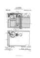
- Figure 1 is a vertical central section of part of a flush tank and flush controlling mechanism embodying the invention.
- Fig. 2 is a top plan view of the parts illustrated in Fig. 1, the siphon and valve being in horizontal section on the line w-w of Fig. 1.
- the numeral 1 designates a flush tank such as is commonly used in connection with closet bowls and the like in lavatories and toilets.
- a flush pipe 2 connects with the bottom of the tank and extends to the bowl or other part to be flushed.
- a siphon embodying a short leg 3 and a long leg 1, the latter connecting with the flush pipe 2.
- a cylinder 5 or like part is arranged within the tank and a plunger 6 is adapted to operate therein, said plunger being sufficiently loose within the cylinder to admit of water passing between the outer edges of the plunger and the walls of the cylinder.
- a casing 7 connects the lower end of the short leg 3 of the siphon with the lower portion of the cylinder 5 and has an opening 8 in its lower end.
- a flap valve is adapted to control the opening 8 and an opening 9, the latter afiording communication between the cylinder and the casing.
- the flap valve comprises two wings or members 10 and 11 which are upwardly diverged and pivoted at 12.
- the wing or member 11 is adapted to control the opening 8, whereas the wing or member 10 controls the opening 9. Both openings 8 and 9 are not closed at the same time. WVhen the valve is moved so as to close the opening 9 water may pass freely from the tank 1 into the short leg of the siphon through the opening 8 and when the opening 8 is closed water may pass from the cylinder 5 into the siphon upon quickly depressing the plunger 6 so as to prime or start the siphon when it is required to flush the bowl or other part.
- a stem 13 is connected at its lower end with the plunger 6 and projects upwardly and is attached at its upper end to an arm 14 of a shaft 15, which is journaled in opposite sides of the tank 1.
- One end of the shaft 15 projects beyond a side of the tank and has an arm 16 to which a chain 17 or other part is connected.
- a spring 18 of helical form is mounted upon the shaft 15 and has oppositely extending arms one of which engages with a part of the tank and the other with the crank 14 so as to hold the plunger 6 elevated.
- the plunger 6 necessarily moves upwardly at a comparatively slow rate of speed because of the small space formed between the outer edge of the plunger and the inner walls of the cylinder.
- a siphon arranged within-thetan'kand having its long 'leg connected with the flush pipe, a siphon arranged within-thetan'kand having its long 'leg connected with the flush pipe, a
- a casing connecting the cylinder with the short leg-of the sip'honand having two openings,-the'one leading into the flush tank and the other leading lnto the cylinder, 'a flap valve comprising diverged members arrangedto alternately closethe'openings of said casing and automatically actuated by the flow of water through said casing, a plunger arranged to operate inthe cylinder and having a small space for the passage of Water thereby, means for depressing the plunger .to ,prime and .start the siphon, and means for automatically returning the plunger tolnorcmal position.
- a casing connecting the lower portion of the cylinder with the loweraend ofithefishort cleg of the siphon and having two openings for establishing communication between 'ithe siphon and the cylinder and flush tank, a
- pivoted flap valve comprising :diverged wings arranged to alternately close the openi'ngsof said casing and automatically oper ated by. the flow of water through said cas- 'ing, a plunger *loosely fitting the cylinder and arranged to operate therein, a shaft mounted upon the flush tank and 'havrng an 'end extending beyond a side thereof and provided with an arm,-said s'haft having a second arm which ie-connectedwith'fthe stem lflopies of this patent'may be :obtained for-five eents each, bymfldressing the fiGommissioner :c'f :LEat-extts.
Landscapes
- Health & Medical Sciences (AREA)
- Life Sciences & Earth Sciences (AREA)
- Engineering & Computer Science (AREA)
- Hydrology & Water Resources (AREA)
- Public Health (AREA)
- Water Supply & Treatment (AREA)
- Sanitary Device For Flush Toilet (AREA)
Description
B. S. HODGKINS.
FLUSH TANK CONTROL.
APPLICATION FILED NOV. 30, 1910.
990, 1 '32. Patented Apr. 18, 1911.
BENJAMIN S. HODGKINS, 0F LEWISTON, MAINE.
FLUSH-TANK CONTROL.
Specification of Letters Patent.
Patented Apr. 18, 1911.
Application filed November 30, 1910. Serial No. 594,857.
To all whom it may concern:
Be it known that I, BENJAMIN S. Hooc- KlNS, a citizen of'the United States, residing at Lewiston, in the county of Androscoggin and State of Maine, have invented new and useful Improvements in Flush-Tank Control, of which the following is a specification.
The present invention provides a mechanism for controlling the outflow of water from a tank used in connection with lavatories and toilets for flushing bowls and other parts to be cleansed, the purpose being to provide a mechanism which is comparatively silent in operation, free from complex parts and so arranged as to prevent a leaky joint between the flush pipe and the tank. 1
The invention consists of the novel features, details of construction and combination of parts, which hereinafter will be more particularly set forth, illustrated in the accompanying drawing, and pointed out in the appended claims.
Referring to the drawing, forming a part of the application, Figure 1 is a vertical central section of part of a flush tank and flush controlling mechanism embodying the invention. Fig. 2 is a top plan view of the parts illustrated in Fig. 1, the siphon and valve being in horizontal section on the line w-w of Fig. 1.
Corresponding and like parts are referred to in the following description, and indicated in all the views of the drawing, by the same reference characters.
The numeral 1 designates a flush tank such as is commonly used in connection with closet bowls and the like in lavatories and toilets. A flush pipe 2 connects with the bottom of the tank and extends to the bowl or other part to be flushed. Within the tank is arranged a siphon embodying a short leg 3 and a long leg 1, the latter connecting with the flush pipe 2. A cylinder 5 or like part is arranged within the tank and a plunger 6 is adapted to operate therein, said plunger being sufficiently loose within the cylinder to admit of water passing between the outer edges of the plunger and the walls of the cylinder. A casing 7 connects the lower end of the short leg 3 of the siphon with the lower portion of the cylinder 5 and has an opening 8 in its lower end. A flap valve is adapted to control the opening 8 and an opening 9, the latter afiording communication between the cylinder and the casing.
The flap valve comprises two wings or members 10 and 11 which are upwardly diverged and pivoted at 12. The wing or member 11 is adapted to control the opening 8, whereas the wing or member 10 controls the opening 9. Both openings 8 and 9 are not closed at the same time. WVhen the valve is moved so as to close the opening 9 water may pass freely from the tank 1 into the short leg of the siphon through the opening 8 and when the opening 8 is closed water may pass from the cylinder 5 into the siphon upon quickly depressing the plunger 6 so as to prime or start the siphon when it is required to flush the bowl or other part.
A stem 13 is connected at its lower end with the plunger 6 and projects upwardly and is attached at its upper end to an arm 14 of a shaft 15, which is journaled in opposite sides of the tank 1. One end of the shaft 15 projects beyond a side of the tank and has an arm 16 to which a chain 17 or other part is connected. A spring 18 of helical form is mounted upon the shaft 15 and has oppositely extending arms one of which engages with a part of the tank and the other with the crank 14 so as to hold the plunger 6 elevated. Upon pulling upon the chain or like part 17 the shaft 15 is turned and the plunger 6 depressed, thereby increasing the tension of the spring 18 and upon releasing the part 17 the plunger 6 is elevated by the action of the spring 18, as will be readily understood. As the plunger 6 moves downwardly in the cylinder 5 the water contained in said cylinder below the plunger is forced into the siphon so as to fill and start the same, the water continuing to flow from the tank through the siphon and flush pipe to the part to be flushed, the flow ceasing only when the level of the water in the tank uncovers the lower end of the valve casing 7. When the plunger 6 is moved downwardly the flap valve shifts automatically to cover the opening 8 and to uncover the opening 9 and when the plunger moves upwardly the valve is shifted by the combined action of the upflow of the water from the tank into the casing 7 through the opening 8 and the suction created upon the member 10 by the upward movement of the plunger 6. The plunger 6 necessarily moves upwardly at a comparatively slow rate of speed because of the small space formed between the outer edge of the plunger and the inner walls of the cylinder. When the plunger is operated by a quick pull upon the part 17 all or nearly all the .water is .forced from the lower portion of the cylinder '5 into the siphon since but very little water escapes through the space formed between the plunger and inner walls of .the cylinder.
From the foregoing description, taken in connection with the accompanying drawing, the advantages of the construction and of the method of operation will be readily apparent to those skilled in the artto which. the invention appertains, and while I have described the principle of operation of the invention, together with the device which nowconsider to be the embodiment thereof,
I desire-to-ha-ve it'understood that the device shown is merely illustrative, and that such changes may be made when desired as are within the scope of the claims appended hereto.
Having thus described the invent-ion what is claimed as new, is
1. In a flush tank having a flush pipe, a siphon arranged within-thetan'kand having its long 'leg connected with the flush pipe, a
cylinder, a casing connecting the cylinder with the short leg-of the sip'honand having two openings,-the'one leading into the flush tank and the other leading lnto the cylinder, 'a flap valve comprising diverged members arrangedto alternately closethe'openings of said casing and automatically actuated by the flow of water through said casing, a plunger arranged to operate inthe cylinder and having a small space for the passage of Water thereby, means for depressing the plunger .to ,prime and .start the siphon, and means for automatically returning the plunger tolnorcmal position.
2. In combination a flush tank, a flush pipe connected therewith, a siphon located within the flush tank and having its long leg'connec'ted with-the flush pipe, a cylinder,
a casing connecting the lower portion of the cylinder with the loweraend ofithefishort cleg of the siphon and having two openings for establishing communication between 'ithe siphon and the cylinder and flush tank, a
pivoted flap valve comprising :diverged wings arranged to alternately close the openi'ngsof said casing and automatically oper ated by. the flow of water through said cas- 'ing, a plunger *loosely fitting the cylinder and arranged to operate therein, a shaft mounted upon the flush tank and 'havrng an 'end extending beyond a side thereof and provided with an arm,-said s'haft having a second arm which ie-connectedwith'fthe stem lflopies of this patent'may be :obtained for-five eents each, bymfldressing the fiGommissioner :c'f :LEat-extts.
Priority Applications (1)
| Application Number | Priority Date | Filing Date | Title |
|---|---|---|---|
| US59485710A US990132A (en) | 1910-11-30 | 1910-11-30 | Flush-tank control. |
Applications Claiming Priority (1)
| Application Number | Priority Date | Filing Date | Title |
|---|---|---|---|
| US59485710A US990132A (en) | 1910-11-30 | 1910-11-30 | Flush-tank control. |
Publications (1)
| Publication Number | Publication Date |
|---|---|
| US990132A true US990132A (en) | 1911-04-18 |
Family
ID=3058469
Family Applications (1)
| Application Number | Title | Priority Date | Filing Date |
|---|---|---|---|
| US59485710A Expired - Lifetime US990132A (en) | 1910-11-30 | 1910-11-30 | Flush-tank control. |
Country Status (1)
| Country | Link |
|---|---|
| US (1) | US990132A (en) |
Cited By (2)
| Publication number | Priority date | Publication date | Assignee | Title |
|---|---|---|---|---|
| US4024589A (en) * | 1975-12-22 | 1977-05-24 | Kohler Co. | Siphon flush valve |
| US4138749A (en) * | 1977-08-04 | 1979-02-13 | Clark Merlin W | Two-stage hydraulic flush control device |
-
1910
- 1910-11-30 US US59485710A patent/US990132A/en not_active Expired - Lifetime
Cited By (2)
| Publication number | Priority date | Publication date | Assignee | Title |
|---|---|---|---|---|
| US4024589A (en) * | 1975-12-22 | 1977-05-24 | Kohler Co. | Siphon flush valve |
| US4138749A (en) * | 1977-08-04 | 1979-02-13 | Clark Merlin W | Two-stage hydraulic flush control device |
Similar Documents
| Publication | Publication Date | Title |
|---|---|---|
| US1248650A (en) | Automatic valve. | |
| US990132A (en) | Flush-tank control. | |
| US1077329A (en) | Flush-tank for water-closets. | |
| US2083486A (en) | Flush valve | |
| US1224734A (en) | Water-closet. | |
| US245319A (en) | John kobertsof | |
| US441045A (en) | Water-closet | |
| US533360A (en) | Inlet-valve for flush-tanks for closets | |
| US1299692A (en) | Flush-valve. | |
| US540042A (en) | Water-closet cistern | |
| US745823A (en) | Flushing apparatus for water-closets. | |
| US249577A (en) | James e | |
| US955518A (en) | Ventilating and flushing apparatus for closets. | |
| US1174811A (en) | Apparatus for operating flush-tanks. | |
| US372964A (en) | Flushing apparatus for siphon water-closets | |
| US424871A (en) | Apparatus for flushing water-closets | |
| US1224845A (en) | Flushing-tank. | |
| US247210A (en) | Water-closet | |
| US263450A (en) | wright | |
| US313281A (en) | Water-closet | |
| US245854A (en) | Water-closet cistern | |
| US365937A (en) | Water closet | |
| US947782A (en) | Water-closet. | |
| US1203726A (en) | Flush-tank-valve-actuating mechanism. | |
| US1174123A (en) | Water-closet fixture. |