US9900683B2 - Headphones - Google Patents
Headphones Download PDFInfo
- Publication number
- US9900683B2 US9900683B2 US15/033,262 US201415033262A US9900683B2 US 9900683 B2 US9900683 B2 US 9900683B2 US 201415033262 A US201415033262 A US 201415033262A US 9900683 B2 US9900683 B2 US 9900683B2
- Authority
- US
- United States
- Prior art keywords
- plate
- drive system
- headphone device
- ear pad
- set forth
- Prior art date
- Legal status (The legal status is an assumption and is not a legal conclusion. Google has not performed a legal analysis and makes no representation as to the accuracy of the status listed.)
- Expired - Fee Related
Links
Images


Classifications
-
- H—ELECTRICITY
- H04—ELECTRIC COMMUNICATION TECHNIQUE
- H04R—LOUDSPEAKERS, MICROPHONES, GRAMOPHONE PICK-UPS OR LIKE ACOUSTIC ELECTROMECHANICAL TRANSDUCERS; ELECTRIC HEARING AIDS; PUBLIC ADDRESS SYSTEMS
- H04R1/00—Details of transducers, loudspeakers or microphones
- H04R1/10—Earpieces; Attachments therefor ; Earphones; Monophonic headphones
- H04R1/1058—Manufacture or assembly
- H04R1/1075—Mountings of transducers in earphones or headphones
-
- H—ELECTRICITY
- H04—ELECTRIC COMMUNICATION TECHNIQUE
- H04R—LOUDSPEAKERS, MICROPHONES, GRAMOPHONE PICK-UPS OR LIKE ACOUSTIC ELECTROMECHANICAL TRANSDUCERS; ELECTRIC HEARING AIDS; PUBLIC ADDRESS SYSTEMS
- H04R1/00—Details of transducers, loudspeakers or microphones
- H04R1/10—Earpieces; Attachments therefor ; Earphones; Monophonic headphones
- H04R1/1008—Earpieces of the supra-aural or circum-aural type
-
- H—ELECTRICITY
- H04—ELECTRIC COMMUNICATION TECHNIQUE
- H04R—LOUDSPEAKERS, MICROPHONES, GRAMOPHONE PICK-UPS OR LIKE ACOUSTIC ELECTROMECHANICAL TRANSDUCERS; ELECTRIC HEARING AIDS; PUBLIC ADDRESS SYSTEMS
- H04R17/00—Piezoelectric transducers; Electrostrictive transducers
- H04R17/005—Piezoelectric transducers; Electrostrictive transducers using a piezoelectric polymer
-
- H—ELECTRICITY
- H04—ELECTRIC COMMUNICATION TECHNIQUE
- H04R—LOUDSPEAKERS, MICROPHONES, GRAMOPHONE PICK-UPS OR LIKE ACOUSTIC ELECTROMECHANICAL TRANSDUCERS; ELECTRIC HEARING AIDS; PUBLIC ADDRESS SYSTEMS
- H04R23/00—Transducers other than those covered by groups H04R9/00 - H04R21/00
- H04R23/02—Transducers using more than one principle simultaneously
-
- H—ELECTRICITY
- H04—ELECTRIC COMMUNICATION TECHNIQUE
- H04R—LOUDSPEAKERS, MICROPHONES, GRAMOPHONE PICK-UPS OR LIKE ACOUSTIC ELECTROMECHANICAL TRANSDUCERS; ELECTRIC HEARING AIDS; PUBLIC ADDRESS SYSTEMS
- H04R3/00—Circuits for transducers
- H04R3/12—Circuits for transducers for distributing signals to two or more loudspeakers
- H04R3/14—Cross-over networks
-
- H—ELECTRICITY
- H04—ELECTRIC COMMUNICATION TECHNIQUE
- H04R—LOUDSPEAKERS, MICROPHONES, GRAMOPHONE PICK-UPS OR LIKE ACOUSTIC ELECTROMECHANICAL TRANSDUCERS; ELECTRIC HEARING AIDS; PUBLIC ADDRESS SYSTEMS
- H04R7/00—Diaphragms for electromechanical transducers; Cones
- H04R7/02—Diaphragms for electromechanical transducers; Cones characterised by the construction
- H04R7/04—Plane diaphragms
-
- H—ELECTRICITY
- H04—ELECTRIC COMMUNICATION TECHNIQUE
- H04R—LOUDSPEAKERS, MICROPHONES, GRAMOPHONE PICK-UPS OR LIKE ACOUSTIC ELECTROMECHANICAL TRANSDUCERS; ELECTRIC HEARING AIDS; PUBLIC ADDRESS SYSTEMS
- H04R9/00—Transducers of moving-coil, moving-strip, or moving-wire type
- H04R9/06—Loudspeakers
-
- H—ELECTRICITY
- H04—ELECTRIC COMMUNICATION TECHNIQUE
- H04R—LOUDSPEAKERS, MICROPHONES, GRAMOPHONE PICK-UPS OR LIKE ACOUSTIC ELECTROMECHANICAL TRANSDUCERS; ELECTRIC HEARING AIDS; PUBLIC ADDRESS SYSTEMS
- H04R17/00—Piezoelectric transducers; Electrostrictive transducers
-
- H—ELECTRICITY
- H04—ELECTRIC COMMUNICATION TECHNIQUE
- H04R—LOUDSPEAKERS, MICROPHONES, GRAMOPHONE PICK-UPS OR LIKE ACOUSTIC ELECTROMECHANICAL TRANSDUCERS; ELECTRIC HEARING AIDS; PUBLIC ADDRESS SYSTEMS
- H04R9/00—Transducers of moving-coil, moving-strip, or moving-wire type
Definitions
- the present invention concerns a headphone device, in particular a headphone or earphone.
- Earphones or headphones have long been known and typically have a peripherally extending ear pad and a voice coil coupled to a diaphragm, the voice coil being driven by a magnet system.
- An object of the present invention is to provide an improved headphone device which is of a simpler structure.
- a headphone device having a surrounding ear pad and a sound generator which has a substantially rigid plate and a drive system for converting electrical signals into mechanical oscillations of the (rigid) plate.
- a flexible portion between the ear pad and the (rigid) plate.
- the flexible portion can provide for decoupling between the plate and the ear pad so that the emission characteristic of the plate can be improved.
- a piezoelectric film on one side of the plate for exciting the plate.
- the drive system which for example can be provided in the ear pad
- a further possible option for exciting the plate In that way it is possible to implement a 2-way transducer.
- the drive system has a magnet system and a voice coil, the voice coil being coupled to the plate.
- the drive system is in the form of a capacitive drive system.
- a frequency crossover for separating the input audio signals into higher-frequency or lower-frequency signals.
- the higher-frequency signals are fed to the piezoelectric film and the lower-frequency signals are fed to the drive system so that the higher-frequency signals are transmitted to the plate by way of the piezoelectric film and the lower-frequency signals are transmitted to the plate by way of the drive system.
- the invention concerns a notion of providing a headphone device having a surrounding ear pad and a sound generator.
- the sound generator has a substantially rigid plate and a drive system for converting electrical signals into mechanical oscillations of the plate.
- the drive system is provided in the ear pad or integrated therein.
- the ear pad is connected directly or indirectly to the plate.
- an at least partially peripherally extending portion which is highly flexible or very flexible so that mobility of the plate can be increased.
- a piezoelectric film adapted to reproduce higher frequencies.
- the cables for the magnet system and the like are laid in the ear pad.
- the plate has at least partially glass and is at least partially transparent.
- the drive system of the sound generator is provided in the ear pad.
- an ear cup of a headphone or earphone is formed from the plate and the ear pad.
- the headphone device has a frequency crossover to pass low frequencies to the drive system and high frequencies to the piezoelectric drive.
- FIG. 1 shows a diagrammatic sectional view of a headphone device according to a first embodiment.
- FIG. 2 shows a diagrammatic sectional view of a headphone device according to a second embodiment.
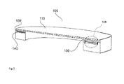
- FIG. 3 shows a diagrammatic sectional view of a headphone device according to an embodiment of the present application.
- FIG. 1 shows a diagrammatic sectional view of a headphone device according to a first embodiment.
- the headphone device 100 has a plate 110 and a surrounding ear pad 120 connected directly or indirectly to the plate 110 .
- the headphone device 100 according to the first embodiment is in the form of an electrodynamic headphone device and has a magnet system 130 as well as a voice coil 140 as the drive system 105 .
- a flexible portion 150 can be provided between the ear pad 120 and the plate 110 .
- the voice coil 140 is coupled directly or indirectly to the plate 110 and excites the plate 110 to produce mechanical oscillations so that the plate 110 outputs an audio signal.
- the magnet system 130 and the voice coil 140 can be coupled by way of a cable within the ear pad to a feed cable of the headphone device, which in turn has a plug by way of which the audio signals to be reproduced can be received as electrical signals, wherein the audio signals are fed to the headphone device by way of the cable so that the audio signal can be reproduced by way of the drive system.
- a flexible portion 150 between the ear pad 120 and the plate 110 is advantageous because that can increase the mobility of the plate 110 whereby improved sound delivery can be achieved.
- the plate 110 can be made from glass or another transparent material.
- At least one electrodynamic drive having a magnet system 130 and a voice coil 140 is provided in the pad 120 .
- the plate 110 which for example is made of glass can emit for example a low-frequency sound (up to about 1 kHz). If the flexible portion 150 is provided between the ear pad 120 and the plate 110 the plate can also emit higher frequencies.
- FIG. 2 shows a diagrammatic sectional view of a headphone device according to a second embodiment.
- the headphone device of the second embodiment substantially corresponds to the headphone device of the first embodiment.
- the difference between the headphone device of the first and second embodiments is that provided on the side of the plate 110 , that is towards the ear, is a piezoelectric film 160 which can be actuated with the higher-frequency audio signals to deliver a higher-frequency audio signal.
- the headphone device according to the second embodiment can be in the form of a two-way transducer, wherein the drive system (with the magnet system 130 and the voice coil 140 ) in the ear pad can deliver lower-frequency audio signals.
- the cables for the magnet system can optionally be laid within the ear pad.
- the plate 110 is optionally in the form of a glass plate.
- the piezoelectric film 160 can also optionally be transparent so that an ear of a user remains visible when wearing the headphone device according to the invention.
- the necessary cables can be integrated in the ear pad. That can be made possible for example by injection molding of the cable therein.
- the headphone device or the ear cup of a headphone device comprises only a (transparent) plate 110 and a surrounding ear pad 120 fitted thereto.
- the drive system for the plate 110 is provided in the ear pad 120 .
- the plate and the ear pad are visible from the exterior.
- the drive system 105 of a headphone device can be in the form of a capacitive drive system (with a counterpart electrode).
- the headphone device has a surrounding pad and a sound generator, wherein the sound generator has a substantially rigid plate and a drive system which is arranged in the ear pad.
- the plate lies on the ear pad.
- the invention concerns a loudspeaker or sound generator having a rigid plate 110 and a drive system 105 for converting electrical signals into mechanical oscillations of the plate 110 .
- a flexible portion or an elastic carrier or a flexible element 150 can be provided between the plate 110 and a fixing means of the plate.
- a sound transducer having a substantially rigid plate 110 and an at least partially surrounding drive system 105 for converting electrical signals into mechanical oscillations of the plate 110 .
- the sound transducer has a corrugation which is coupled to a fixing means by way of an elastic carrier or a flexible holding unit.
- FIG. 3 shows a diagrammatic view of a headphone device that has a capacitive drive system 105 .
Landscapes
- Engineering & Computer Science (AREA)
- Physics & Mathematics (AREA)
- Acoustics & Sound (AREA)
- Signal Processing (AREA)
- Multimedia (AREA)
- Manufacturing & Machinery (AREA)
- Health & Medical Sciences (AREA)
- General Health & Medical Sciences (AREA)
- Otolaryngology (AREA)
- Headphones And Earphones (AREA)
- Telephone Set Structure (AREA)
- Piezo-Electric Transducers For Audible Bands (AREA)
Abstract
Description
Claims (10)
Applications Claiming Priority (4)
| Application Number | Priority Date | Filing Date | Title |
|---|---|---|---|
| DE102013222231 | 2013-10-31 | ||
| DE201310222231 DE102013222231A1 (en) | 2013-10-31 | 2013-10-31 | receiver |
| DE102013222231.9 | 2013-10-31 | ||
| PCT/EP2014/073429 WO2015063257A1 (en) | 2013-10-31 | 2014-10-31 | Headphones |
Publications (2)
| Publication Number | Publication Date |
|---|---|
| US20160286320A1 US20160286320A1 (en) | 2016-09-29 |
| US9900683B2 true US9900683B2 (en) | 2018-02-20 |
Family
ID=52006974
Family Applications (1)
| Application Number | Title | Priority Date | Filing Date |
|---|---|---|---|
| US15/033,262 Expired - Fee Related US9900683B2 (en) | 2013-10-31 | 2014-10-31 | Headphones |
Country Status (4)
| Country | Link |
|---|---|
| US (1) | US9900683B2 (en) |
| CN (1) | CN105981402A (en) |
| DE (1) | DE102013222231A1 (en) |
| WO (1) | WO2015063257A1 (en) |
Families Citing this family (2)
| Publication number | Priority date | Publication date | Assignee | Title |
|---|---|---|---|---|
| CN104822114A (en) * | 2015-04-22 | 2015-08-05 | 歌尔声学股份有限公司 | Speaker device |
| JP6767638B2 (en) * | 2016-10-28 | 2020-10-14 | パナソニックIpマネジメント株式会社 | Bone conduction speaker and bone conduction headphone device |
Citations (18)
| Publication number | Priority date | Publication date | Assignee | Title |
|---|---|---|---|---|
| DE2428933A1 (en) | 1973-06-19 | 1975-01-23 | Akg Akustische Kino Geraete | HEADPHONES ACCORDING TO THE TWO-WAY SYSTEM |
| US3894198A (en) | 1971-11-04 | 1975-07-08 | Kureha Chemical Ind Co Ltd | Electrostatic-piezoelectric transducer |
| US4198550A (en) | 1977-11-26 | 1980-04-15 | Sony Corporation | Peripherally reinforced laminated loudspeaker diaphragm |
| US4418248A (en) * | 1981-12-11 | 1983-11-29 | Koss Corporation | Dual element headphone |
| US4447678A (en) | 1980-07-28 | 1984-05-08 | Akg Akustische U.Kino-Gerate Gesellschaft Mbh | Electracoustic transducer |
| US5430803A (en) * | 1992-03-31 | 1995-07-04 | Soei Electric Co., Ltd. | Bifunctional earphone set |
| WO2000046786A2 (en) | 1999-02-05 | 2000-08-10 | New Transducers Limited | A headphone comprising bending-wave loudspeakears |
| US20010026625A1 (en) * | 1998-07-03 | 2001-10-04 | Henry Azima | Resonant panel-form loudspeaker |
| US20050008184A1 (en) * | 2001-12-18 | 2005-01-13 | Tomohiro Ito | Headset |
| US20050197565A1 (en) * | 2004-03-02 | 2005-09-08 | Azden Corporation | Audio communication apparatus for MRI apparatus |
| US20100284558A1 (en) * | 2009-05-08 | 2010-11-11 | Tominori Kimura | Earmuff and Headphone |
| US20150326974A1 (en) * | 2014-05-08 | 2015-11-12 | Jps Labs Llc | Single magnet planar-magnetic transducer |
| US20150373460A1 (en) * | 2014-06-18 | 2015-12-24 | Jetvox Acoustic Corp. | Piezoelectric-type speaker |
| US20160119719A1 (en) * | 2014-10-24 | 2016-04-28 | Taiyo Yuden Co., Ltd. | Electroacoustic converter and electronic device |
| US20160127820A1 (en) * | 2014-10-31 | 2016-05-05 | Jetvox Acoustic Corp. | Piezoelectric ceramic dual-frequency earphone structure |
| US9351075B2 (en) * | 2013-11-27 | 2016-05-24 | Panasonic Intellectual Property Management Co., Ltd. | Body-sensitive vibration headphone |
| US20160277823A1 (en) * | 2015-03-20 | 2016-09-22 | Jetvox Acoustic Corp. | Piezoelectric ceramic dual-band bass-enhanced earpiece |
| US20170180863A1 (en) * | 2015-09-16 | 2017-06-22 | Taction Technology Inc. | Apparatus and methods for audio-tactile spatialization of sound and perception of bass |
Family Cites Families (6)
| Publication number | Priority date | Publication date | Assignee | Title |
|---|---|---|---|---|
| US6597792B1 (en) * | 1999-07-15 | 2003-07-22 | Bose Corporation | Headset noise reducing |
| JP2003032768A (en) * | 2001-07-19 | 2003-01-31 | Matsushita Electric Ind Co Ltd | headphone |
| EP2098096A1 (en) * | 2006-11-23 | 2009-09-09 | Nxp B.V. | Membrane for an electroacoustic transducer and acoustic device |
| JP5269618B2 (en) * | 2009-01-05 | 2013-08-21 | 株式会社オーディオテクニカ | Bone conduction microphone built-in headset |
| JP5910119B2 (en) * | 2012-01-31 | 2016-04-27 | ソニー株式会社 | headphone |
| CN202856947U (en) * | 2012-08-31 | 2013-04-03 | 中山市天键电声有限公司 | Earplug type earphone |
-
2013
- 2013-10-31 DE DE201310222231 patent/DE102013222231A1/en active Pending
-
2014
- 2014-10-31 CN CN201480059850.7A patent/CN105981402A/en active Pending
- 2014-10-31 US US15/033,262 patent/US9900683B2/en not_active Expired - Fee Related
- 2014-10-31 WO PCT/EP2014/073429 patent/WO2015063257A1/en not_active Ceased
Patent Citations (20)
| Publication number | Priority date | Publication date | Assignee | Title |
|---|---|---|---|---|
| US3894198A (en) | 1971-11-04 | 1975-07-08 | Kureha Chemical Ind Co Ltd | Electrostatic-piezoelectric transducer |
| DE2428933A1 (en) | 1973-06-19 | 1975-01-23 | Akg Akustische Kino Geraete | HEADPHONES ACCORDING TO THE TWO-WAY SYSTEM |
| US3943304A (en) * | 1973-06-19 | 1976-03-09 | Akg Akustische U Kino-Gerate Gesellschaft M.B.H. | Headphone operating on the two-way system |
| US4198550A (en) | 1977-11-26 | 1980-04-15 | Sony Corporation | Peripherally reinforced laminated loudspeaker diaphragm |
| US4447678A (en) | 1980-07-28 | 1984-05-08 | Akg Akustische U.Kino-Gerate Gesellschaft Mbh | Electracoustic transducer |
| US4418248A (en) * | 1981-12-11 | 1983-11-29 | Koss Corporation | Dual element headphone |
| US5430803A (en) * | 1992-03-31 | 1995-07-04 | Soei Electric Co., Ltd. | Bifunctional earphone set |
| US20010026625A1 (en) * | 1998-07-03 | 2001-10-04 | Henry Azima | Resonant panel-form loudspeaker |
| WO2000046786A2 (en) | 1999-02-05 | 2000-08-10 | New Transducers Limited | A headphone comprising bending-wave loudspeakears |
| US20050008184A1 (en) * | 2001-12-18 | 2005-01-13 | Tomohiro Ito | Headset |
| US20050197565A1 (en) * | 2004-03-02 | 2005-09-08 | Azden Corporation | Audio communication apparatus for MRI apparatus |
| US20100284558A1 (en) * | 2009-05-08 | 2010-11-11 | Tominori Kimura | Earmuff and Headphone |
| US9351075B2 (en) * | 2013-11-27 | 2016-05-24 | Panasonic Intellectual Property Management Co., Ltd. | Body-sensitive vibration headphone |
| US20150326974A1 (en) * | 2014-05-08 | 2015-11-12 | Jps Labs Llc | Single magnet planar-magnetic transducer |
| US20150373460A1 (en) * | 2014-06-18 | 2015-12-24 | Jetvox Acoustic Corp. | Piezoelectric-type speaker |
| US20160119719A1 (en) * | 2014-10-24 | 2016-04-28 | Taiyo Yuden Co., Ltd. | Electroacoustic converter and electronic device |
| US20160119721A1 (en) * | 2014-10-24 | 2016-04-28 | Taiyo Yuden Co., Ltd. | Electroacoustic converter |
| US20160127820A1 (en) * | 2014-10-31 | 2016-05-05 | Jetvox Acoustic Corp. | Piezoelectric ceramic dual-frequency earphone structure |
| US20160277823A1 (en) * | 2015-03-20 | 2016-09-22 | Jetvox Acoustic Corp. | Piezoelectric ceramic dual-band bass-enhanced earpiece |
| US20170180863A1 (en) * | 2015-09-16 | 2017-06-22 | Taction Technology Inc. | Apparatus and methods for audio-tactile spatialization of sound and perception of bass |
Non-Patent Citations (1)
| Title |
|---|
| International Search Report for Application No. PCT/EP2014/073429 dated Feb. 6, 2015. |
Also Published As
| Publication number | Publication date |
|---|---|
| US20160286320A1 (en) | 2016-09-29 |
| CN105981402A (en) | 2016-09-28 |
| DE102013222231A1 (en) | 2015-04-30 |
| WO2015063257A1 (en) | 2015-05-07 |
Similar Documents
| Publication | Publication Date | Title |
|---|---|---|
| US10397685B2 (en) | Earphone | |
| US8488831B2 (en) | In-ear monitor with concentric sound bore configuration | |
| CN104272765B (en) | earphone | |
| US10313801B2 (en) | Sound output device comprises a dual speaker including a dynamic speaker and a piezoelectric speaker | |
| JP7412029B2 (en) | Electroacoustic transducer and electroacoustic transducer | |
| US9107014B2 (en) | Multifunctional earphone | |
| JP2009260883A (en) | Earphone for person with hearing loss | |
| JPWO2009141912A1 (en) | Earphone device | |
| CN101690261A (en) | Small-sized sound receiver for producing body-sensing vibration | |
| CN105340291A (en) | Bone conduction speaker unit | |
| KR20200109406A (en) | Mini bone conductive speaker | |
| US9532132B2 (en) | Hearing-impaired person assistance speaker | |
| KR101096546B1 (en) | Condensor type speaker | |
| CN103369423A (en) | In-ear earphone | |
| KR101381255B1 (en) | Hybrid microspeaker | |
| US9900683B2 (en) | Headphones | |
| KR101470983B1 (en) | Micro speaker | |
| US9906850B2 (en) | Headphone unit | |
| CN206024102U (en) | Horn single body and it is provided with the earphone of the horn single body | |
| CN104507018A (en) | Dual-drive miniature loudspeaker | |
| CN109936802A (en) | Diaphragms and Electroacoustic Transducers | |
| US20140226833A1 (en) | Headphone device | |
| CN103391500A (en) | Piezoelectric ceramic bone-conduction receiver vibrator and mounting structure thereof | |
| JP2006207108A (en) | Helmet with speaker, and communication system | |
| KR101469559B1 (en) | Backpack |
Legal Events
| Date | Code | Title | Description |
|---|---|---|---|
| AS | Assignment |
Owner name: SENNHEISER ELECTRONIC GMBH & CO. KG, GERMANY Free format text: ASSIGNMENT OF ASSIGNORS INTEREST;ASSIGNORS:STEIN (NE SCHULZE), ELMAR;GRANDT, ANDRE;SIGNING DATES FROM 20160504 TO 20160525;REEL/FRAME:038728/0439 |
|
| STCF | Information on status: patent grant |
Free format text: PATENTED CASE |
|
| MAFP | Maintenance fee payment |
Free format text: PAYMENT OF MAINTENANCE FEE, 4TH YEAR, LARGE ENTITY (ORIGINAL EVENT CODE: M1551); ENTITY STATUS OF PATENT OWNER: LARGE ENTITY Year of fee payment: 4 |
|
| AS | Assignment |
Owner name: SENNHEISER CONSUMER AUDIO GMBH, GERMANY Free format text: ASSIGNMENT OF ASSIGNORS INTEREST;ASSIGNOR:SENNHEISER ELECTRONIC GMBH & CO. KG;REEL/FRAME:058861/0708 Effective date: 20220201 |
|
| FEPP | Fee payment procedure |
Free format text: MAINTENANCE FEE REMINDER MAILED (ORIGINAL EVENT CODE: REM.); ENTITY STATUS OF PATENT OWNER: LARGE ENTITY |
|
| LAPS | Lapse for failure to pay maintenance fees |
Free format text: PATENT EXPIRED FOR FAILURE TO PAY MAINTENANCE FEES (ORIGINAL EVENT CODE: EXP.); ENTITY STATUS OF PATENT OWNER: LARGE ENTITY |
|
| STCH | Information on status: patent discontinuation |
Free format text: PATENT EXPIRED DUE TO NONPAYMENT OF MAINTENANCE FEES UNDER 37 CFR 1.362 |
|
| FP | Lapsed due to failure to pay maintenance fee |
Effective date: 20260220 |