US9900570B2 - Projector system and calibration board - Google Patents
Projector system and calibration board Download PDFInfo
- Publication number
- US9900570B2 US9900570B2 US15/126,976 US201415126976A US9900570B2 US 9900570 B2 US9900570 B2 US 9900570B2 US 201415126976 A US201415126976 A US 201415126976A US 9900570 B2 US9900570 B2 US 9900570B2
- Authority
- US
- United States
- Prior art keywords
- projector
- calibration
- projection image
- group
- markers
- Prior art date
- Legal status (The legal status is an assumption and is not a legal conclusion. Google has not performed a legal analysis and makes no representation as to the accuracy of the status listed.)
- Expired - Fee Related, expires
Links
Images


Classifications
-
- H—ELECTRICITY
- H04—ELECTRIC COMMUNICATION TECHNIQUE
- H04N—PICTORIAL COMMUNICATION, e.g. TELEVISION
- H04N9/00—Details of colour television systems
- H04N9/12—Picture reproducers
- H04N9/31—Projection devices for colour picture display, e.g. using electronic spatial light modulators [ESLM]
- H04N9/3191—Testing thereof
- H04N9/3194—Testing thereof including sensor feedback
-
- G—PHYSICS
- G03—PHOTOGRAPHY; CINEMATOGRAPHY; ANALOGOUS TECHNIQUES USING WAVES OTHER THAN OPTICAL WAVES; ELECTROGRAPHY; HOLOGRAPHY
- G03B—APPARATUS OR ARRANGEMENTS FOR TAKING PHOTOGRAPHS OR FOR PROJECTING OR VIEWING THEM; APPARATUS OR ARRANGEMENTS EMPLOYING ANALOGOUS TECHNIQUES USING WAVES OTHER THAN OPTICAL WAVES; ACCESSORIES THEREFOR
- G03B21/00—Projectors or projection-type viewers; Accessories therefor
- G03B21/14—Details
-
- G—PHYSICS
- G03—PHOTOGRAPHY; CINEMATOGRAPHY; ANALOGOUS TECHNIQUES USING WAVES OTHER THAN OPTICAL WAVES; ELECTROGRAPHY; HOLOGRAPHY
- G03B—APPARATUS OR ARRANGEMENTS FOR TAKING PHOTOGRAPHS OR FOR PROJECTING OR VIEWING THEM; APPARATUS OR ARRANGEMENTS EMPLOYING ANALOGOUS TECHNIQUES USING WAVES OTHER THAN OPTICAL WAVES; ACCESSORIES THEREFOR
- G03B43/00—Testing correct operation of photographic apparatus or parts thereof
-
- G—PHYSICS
- G06—COMPUTING OR CALCULATING; COUNTING
- G06F—ELECTRIC DIGITAL DATA PROCESSING
- G06F3/00—Input arrangements for transferring data to be processed into a form capable of being handled by the computer; Output arrangements for transferring data from processing unit to output unit, e.g. interface arrangements
- G06F3/14—Digital output to display device ; Cooperation and interconnection of the display device with other functional units
- G06F3/1415—Digital output to display device ; Cooperation and interconnection of the display device with other functional units with means for detecting differences between the image stored in the host and the images displayed on the displays
-
- H—ELECTRICITY
- H04—ELECTRIC COMMUNICATION TECHNIQUE
- H04N—PICTORIAL COMMUNICATION, e.g. TELEVISION
- H04N1/00—Scanning, transmission or reproduction of documents or the like, e.g. facsimile transmission; Details thereof
- H04N1/00002—Diagnosis, testing or measuring; Detecting, analysing or monitoring not otherwise provided for
- H04N1/00007—Diagnosis, testing or measuring; Detecting, analysing or monitoring not otherwise provided for relating to particular apparatus or devices
- H04N1/00015—Reproducing apparatus
-
- H—ELECTRICITY
- H04—ELECTRIC COMMUNICATION TECHNIQUE
- H04N—PICTORIAL COMMUNICATION, e.g. TELEVISION
- H04N1/00—Scanning, transmission or reproduction of documents or the like, e.g. facsimile transmission; Details thereof
- H04N1/00002—Diagnosis, testing or measuring; Detecting, analysing or monitoring not otherwise provided for
- H04N1/00026—Methods therefor
- H04N1/00045—Methods therefor using a reference pattern designed for the purpose, e.g. a test chart
-
- H—ELECTRICITY
- H04—ELECTRIC COMMUNICATION TECHNIQUE
- H04N—PICTORIAL COMMUNICATION, e.g. TELEVISION
- H04N1/00—Scanning, transmission or reproduction of documents or the like, e.g. facsimile transmission; Details thereof
- H04N1/00002—Diagnosis, testing or measuring; Detecting, analysing or monitoring not otherwise provided for
- H04N1/00071—Diagnosis, testing or measuring; Detecting, analysing or monitoring not otherwise provided for characterised by the action taken
- H04N1/00082—Adjusting or controlling
- H04N1/00087—Setting or calibrating
-
- H—ELECTRICITY
- H04—ELECTRIC COMMUNICATION TECHNIQUE
- H04N—PICTORIAL COMMUNICATION, e.g. TELEVISION
- H04N9/00—Details of colour television systems
- H04N9/12—Picture reproducers
- H04N9/31—Projection devices for colour picture display, e.g. using electronic spatial light modulators [ESLM]
- H04N9/3179—Video signal processing therefor
- H04N9/3185—Geometric adjustment, e.g. keystone or convergence
-
- G—PHYSICS
- G09—EDUCATION; CRYPTOGRAPHY; DISPLAY; ADVERTISING; SEALS
- G09G—ARRANGEMENTS OR CIRCUITS FOR CONTROL OF INDICATING DEVICES USING STATIC MEANS TO PRESENT VARIABLE INFORMATION
- G09G2320/00—Control of display operating conditions
- G09G2320/06—Adjustment of display parameters
- G09G2320/0693—Calibration of display systems
-
- H—ELECTRICITY
- H04—ELECTRIC COMMUNICATION TECHNIQUE
- H04N—PICTORIAL COMMUNICATION, e.g. TELEVISION
- H04N2201/00—Indexing scheme relating to scanning, transmission or reproduction of documents or the like, and to details thereof
- H04N2201/0077—Types of the still picture apparatus
- H04N2201/0089—Image display device
Definitions
- the present invention relates to calibration and registration for a projector system.
- the projection mapping is also introduced into an entertainment field because the projection of unrealistic image can give pleasure to the eyes of audience (Patent Literature 1).
- a projector requires calibration before use.
- Calibration of projector is achieved by an application of the conventional technology related to calibration of camera.
- a camera parameter can be obtained by calculation.
- calibration of projector can also be calculated if the correspondency between a projection image and a spatial point where the image is projected is found.
- a space encoding method is applied. Structural light from the projector is projected to encode a space by using binary code. Thus encoded space is decoded on the basis of the image acquired by the camera. The correspondency between pixels of the projector and pixels of the camera is checked. Accordingly, a camera image can be converted into a projector image.
- the present invention was made in order to solve the above described problem.
- a purpose of the present invention is to provide a simple projector system which can be handled by a person who is not an expert of image processing technology, more specifically, by experts of different fields.
- a projector system of the present invention capable of solving the above described problem includes a projector, an image processing apparatus, external input means, and a calibration board, wherein the calibration board is made of at least two plane surfaces, each plane surface including a plurality of calibration markers arranged so as to form a regular matrix, and wherein the image processing apparatus includes a projection image coordinate system setting unit for setting a coordinate system of a projection image from the projector, a cursor operating unit for operating a cursor projected from the projector on the basis of position information from the external input means, a cursor coordinates acquiring unit which determines, when the cursor moves to an arbitrary position, the arbitrary position as a selected position based on a selection instruction from the external input means and acquires projection image coordinates corresponding to the cursor at the selected position, a projector characteristics acquiring unit for acquiring projector characteristics for each plane surface on the basis of a group of a projection image coordinate points of the calibration markers acquired by the cursor operating unit and the cursor coordinates acquiring unit and a group of known
- a projector system of the present invention capable of solving the above described problem includes a projector, an image processing apparatus, and external input means
- the image processing apparatus includes a projection image coordinate system setting unit for setting a coordinate system of a projection image from the projector, a cursor operating unit for operating a cursor projected from the projector on the basis of position information from the external input means, a cursor coordinates acquiring unit which determines, when the cursor moves to an arbitrary position, the arbitrary position as a selected position based on a selection instruction from the external input means and acquires projection image coordinates corresponding to the cursor at the selected position, a lens characteristics acquiring unit for inputting lens characteristics of the projector, a spatial coordinates inputting unit for inputting a group of spatial coordinate points of the registration markers provided on a surface of a projected object, and a projected object positional characteristics acquiring unit for acquiring projected object positional characteristics on the basis of a group of projection image coordinate points of the registration markers obtained by the cursor operating unit and the cursor coordinates acquiring unit
- a projector system of the present invention capable of solving the above described problem includes a projector, an image processing apparatus, and external input means
- the image processing apparatus includes a projection image coordinate system setting unit for setting a coordinate system of a projection image from the projector, a cursor operating unit for operating a cursor projected from the projector on the basis of position information from the external input means, and a cursor coordinates acquiring unit which acquires, when an arbitrary position is selected by the cursor operation, projection image coordinates corresponding to the cursor at the selected position based on a selection instruction from the external input means.
- a group of projection image coordinate points of the calibration markers or a group of projection image coordinate points of the registration markers can be acquired by the cursor operating unit and the cursor coordinates acquiring unit. More specifically, the cursor projected from the projector can be used as an intuitive coordinates input interface. As a result, simple calibration and registration can be achieved even without using a camera.
- the spatial coordinates inputting unit further inputs a group of spatial coordinate points of a target within a projected object
- the image processing apparatus further includes a group of target projection image coordinate points acquiring unit which acquires a group of projection image coordinate points of target on the basis of the lens characteristics, the projected object positional characteristics, and the group of spatial coordinate points of target.
- the target image can be projected onto the projected object with ease.
- the image processing apparatus further includes a group of registration marker confirming-projection image coordinates re-acquiring unit which re-acquires a group of registration marker confirming projection image coordinate points on the basis of the lens characteristics, the projected object positional characteristics, and the group of spatial coordinate points of the registration markers.
- the spatial coordinates inputting unit inputs spatial coordinates of the confirmation markers provided on a surface of the projected object
- the image processing apparatus further includes a confirmation marker projection image coordinates acquiring unit that acquires projection image coordinates of the confirmation markers on the basis of the lens characteristics, the projected object positional characteristics, and spatial coordinates of the confirmation markers.
- the projector system of the present invention has a simple structure and can be handled by a person who is not an expert of image processing technology, more specifically, by experts of different fields.
- the existing technology can be improved by combining the projection mapping technology with the existing technology of every field.
- FIG. 1 is a functional block diagram of the image processing apparatus (calibration).
- FIG. 2 is a processing flow chart of the image processing apparatus (calibration).
- FIG. 3 is an operational conception diagram (calibration).
- FIG. 4 is a precision verification graph (calibration).
- FIG. 5 is a functional block diagram of the image processing apparatus (registration).
- FIG. 6 is a processing flow chart of the image processing apparatus (registration).
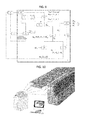
- FIG. 7 is an operational conception diagram (registration).
- FIG. 8 is a functional block diagram of the image processing apparatus (registration confirmation).
- FIG. 9 is a functional block diagram of the image processing apparatus (registration confirmation).
- FIG. 10 illustrates Application Example 1.
- FIG. 11 illustrates Application Example 2.
- FIG. 12 illustrates Application Example 3.
- a projector system includes a projector 1 , an image processing apparatus 2 , external input means 3 , and a calibration board 4 .
- the projector 1 is a typical projector which is commercially available from mass retailers. In other words, the projector 1 is not a special projector that is used, for example, in an event introducing projection mapping.
- the image processing apparatus 2 is a typical personal computer (PC) which is commercially available from mass retailers.
- the image processing apparatus 2 is connected to the projector 1 by wire or by wireless means.
- a typical tablet type computer which is commercially available from mass retailers may be employed as the image processing apparatus 2 .
- the external input means 3 is, for example, a mouse, a track ball, or a touch pad.
- the external input means 3 is a touch panel.
- the calibration board 4 is made of at least two plane surfaces.
- the calibration board 4 is made into a self-standing calibration board having three surfaces, i.e., first plane surface, second plane surface, and third plane surface (see, FIG. 3 ).
- the first plane surface and the second plane surface are formed into a protruding shape when viewed from the front, and the second plane surface and the third plane surface are formed into a depressing shape when viewed from the front. This makes it possible for the surfaces to mate with both of the depressing shape and the protruding shape.
- Each plane surface includes a plurality of calibration markers which are arranged so as to form a regular matrix.
- each plane surface is provided with a checker flag pattern, and each intersection point of the checker flag serves as a calibration marker.
- the preferable number of the intersection points in the checker flag is 8-20 points (This will be studied below).
- FIG. 1 is a functional block diagram of the image processing apparatus 2 .
- the image processing apparatus 2 includes a projection image coordinate system setting unit 11 , a cursor operating unit 12 , a cursor coordinates acquiring unit 13 , a projector characteristics acquiring unit 14 , and a lens characteristics acquiring unit 15 .
- the projection image coordinate system setting unit 11 inputs pixel information of the projector 1 and sets a coordinate system of a projection image from the projector 1 .
- the projection image coordinate system setting unit 11 sets, for example, a coordinate system of 1280 ⁇ 800.
- a cursor projected from the projector 1 is employed as a coordinates input interface.
- the cursor operating unit 12 operates a cursor in synchronization with operation of mouse 3 , etc. on the basis of position information of the mouse 3 .
- the cursor operation enables the cursor to be registered onto a calibration marker.
- the cursor coordinates acquiring unit 13 determines, when the cursor exists at an arbitrary position, the arbitrary position as a selected position based on a selection instruction (e.g., a click of the mouse 3 ) and acquires projection image coordinates (x, y) corresponding to the cursor at the selected position.
- a selection instruction e.g., a click of the mouse 3
- projection image coordinates of the calibration marker can be acquired.
- a group of projection image coordinate points m 1 , m 2 of calibration markers can be acquired for each plane surface by the cursor operating unit 12 and the cursor coordinates acquiring unit 13 .
- the number of plane surfaces is 2.
- the group of coordinate points means coordinates of a group of points or coordinates of a group of markers.
- m projection image coordinates
- P is a matrix indicating projector characteristics
- M is spatial coordinates
- a plurality of calibration markers is arranged so as to form a regular matrix. A positional relationship therebetween in the regular matrix is known. Therefore, a group of spatial coordinate points M of calibration markers is known.
- the projector characteristics acquiring unit 14 acquires projector characteristics P on the basis of the group of spatial coordinate points M of calibration markers and the group of projection image coordinate points m 1 , m 2 of calibration markers of each plane surface.
- Lens characteristics P L and positional characteristics P R are included in the projector characteristics P.
- the lens characteristics P L is also referred to as internal parameter.
- the positional characteristics P R is also referred to as external parameter.
- the lens characteristics acquiring unit 15 removes calibration board positional characteristics P R1 , P R2 of each plane surface on the basis of the projector characteristics P 1 , P 2 of each plane surface and acquires the lens characteristics P L of the projector 1 . More specifically, since the unknown number of the lens characteristics (internal parameter) is 5 and the unknown number of the positional characteristics (external parameter) is 6, the simultaneous equation for computing the total 11 unknown numbers is solved.
- FIG. 2 illustrates a processing flow of the image processing apparatus 2 .
- FIG. 3 is an operational conception diagram related to the calibration.
- the image processing apparatus 2 inputs pixel information of the projector 1 (e.g., 1280 ⁇ 800) and sets a coordinate system of a projection image from the projector 1 (step S 11 ).
- the calibration board 4 is placed within a projection range of the projector 1 .
- the projector 1 projects a cursor onto the calibration board 4 .
- An operator operates the mouse 3 to move the cursor in synchronization with a position of the mouse 3 (step S 12 - 1 ).
- the operator while seeing the cursor, operates the mouse 3 , thereby moving and placing the cursor onto a calibration marker. In this state, the operator clicks the mouse 3 to select the calibration marker (step S 12 - 2 ).
- Projection image coordinates corresponding to the calibration marker is acquired based on a selection instruction of the mouse 3 (step S 12 - 3 ).
- a dotted square suggests a projection image coordinate system.
- the image processing apparatus 2 acquires projection image coordinates corresponding to 20 calibration markers for each of the first plane surface to the third plane surface (repeating steps S 12 - 1 to S 12 - 3 ), thereby acquiring a group of projection image coordinate points m 1 , m 2 , . . . of calibration markers for each plane surface (step S 12 ).
- the group of spatial coordinate points M of calibration markers is known.
- the calibration marker is given as three-dimensional coordinates.
- the image processing apparatus 2 acquires projector characteristics P 1 , P 2 for each plane surface on the basis of the group of projection image coordinate points m 1 , m 2 of calibration markers and the group of spatial coordinate points M of calibration markers (step S 12 ).
- the image processing apparatus 2 removes, on the basis of the projector characteristics P 1 , P 2 of each plane surface, the calibration board positional characteristics P R1 , P R2 of each plane surface, thereby acquiring common lens characteristics P L of the projector (step S 13 ).
- the calibration of the present embodiment was compared with that of the conventional method (in which a camera is used), and verification of precision was performed therebetween.
- the precision was evaluated by re-projection error.
- the re-projection error is an index indicating precision of parameter obtained by calculation. As the value becomes smaller, the obtained parameter can be evaluated as more precise.
- the verification was performed 10 times in the conventional method.
- the verification was performed 6 times in the present embodiment.
- the present test was performed for evaluating errors and variations, so that a positional relationship between the projector and the calibration board (checker board) was changed every time.
- FIG. 4 illustrates a result of evaluation
- the result indicates less precision when compared with the conventional method.
- the board with a single surface is not practical in use since there occurs calculation error (which is also referred to as rank deficient).
- the result indicates about the same level of precision as the conventional method.
- the result indicates better precision than the conventional method.
- the calibration board it is necessary for the calibration board to be made of at least two surfaces. It is more preferable for the calibration board to be made of more than three surfaces. Precision can be secured when the number of intersection points for each plane surface is 8-20 points.
- calibration markers are selected by the mouse 3 . This can be used by a person who is not an expert of image processing technology with the use of an intuitive interface.
- the calibration board 4 except for the calibration board 4 , the projector 1 , the personal computer 2 , and the mouse 3 which are commercially available from mass retailers are employed. Also, the calibration board 4 can be made with ease. This allows easy building of system.
- a projector system includes a projector 1 , an image processing apparatus 2 , and external input means 3 . It is reasonable that the structure related to registration is added to the structure related to calibration. Here, for the sake of convenience, description will be made provided that both are independent from each other. The same reference numerals shall be attached to the corresponding structures and description thereof will be omitted here.
- FIG. 5 is a functional block diagram of the image processing apparatus 2 .
- the image processing apparatus 2 includes a projection image coordinate system setting unit 11 , a cursor operating unit 12 , a cursor coordinates acquiring unit 13 , a lens characteristics acquiring unit 15 , a spatial coordinates inputting unit 21 , and a projected object positional characteristics acquiring unit 22 .
- FIG. 5 a group of target projection image coordinate points acquiring unit 23 that is a structure related to target image projection is supplementary illustrated.
- Structures of the projection image coordinate system setting unit 11 , the cursor operating unit 12 , and the cursor coordinates acquiring unit 13 are identical to the structures thereof related to calibration.
- the lens characteristics acquiring unit 15 inputs lens characteristics P L obtained by calibration.
- m is projection image coordinates
- P L is a matrix indicating lens characteristics (internal parameter)
- P R is a matrix indicating positional characteristics (external parameter)
- M is spatial coordinates.
- a surface of a projected object is preliminary provided with a plurality of registration markers. Therefore, a group of projection image coordinate points m m of registration markers can be acquired by the cursor operating unit 12 and the cursor coordinates acquiring unit 13 .
- a cursor projected from the projector 1 is employed as coordinates input interface.
- the spatial coordinates inputting unit 21 inputs a group of spatial coordinate points M m of a plurality of registration markers provided on the surface of the projected object and a group of spatial coordinate points M t of a target within the projected object from the outside. Incidentally, if only for the purpose of registration, it is sufficient to only acquire the group of spatial coordinate points M m of registration markers.
- the projected object positional characteristics acquiring unit 22 acquires projected object positional characteristics P R on the basis of the group of projection image coordinate points m m of registration markers and the group of spatial coordinate points M m of registration markers.
- the group of target projection image coordinate points acquiring unit 23 acquires a group of projection image coordinate points m t of target on the basis of the lens characteristics P L , the projected object positional characteristics P R , and the group of spatial coordinate points M t of target.
- FIG. 6 illustrates a processing flow of the image processing apparatus 2 .
- FIG. 7 is an operational conception diagram related to the registration.
- the image processing apparatus 2 inputs pixel information (e.g., 1280 ⁇ 800) of the projector 1 and sets a coordinate system of a projection image from the projector 1 (step S 21 ).
- pixel information e.g., 1280 ⁇ 800
- the projector 1 is arranged in a manner that a projected object (specifically, all the registration markers) exists within a projection range of the projector 1 .
- a cursor is projected onto the projected object from the projector 1 .
- An operator operates the mouse 3 to move the cursor in synchronization with a position of the mouse 3 (step S 22 - 1 ).
- the operator while seeing the cursor, operates the mouse 3 , thereby placing the cursor onto a registration marker. In this state, the operator clicks the mouse 3 , thereby selecting the registration marker (step S 12 - 2 ).
- the image processing apparatus 2 acquires projection image coordinates corresponding to the registration marker based on a selection instruction of the mouse 3 (step S 22 - 3 ).
- FIG. 7 a dotted square suggests a projection image coordinate system. Further, FIG. 7 illustrates an example of obtaining projection image coordinates m m1 corresponding to the registration marker m 1 .
- the image processing apparatus 2 acquires projection image coordinates corresponding to each of the 5 registration markers m 1 -m 5 (repeating steps S 22 - 1 to S 22 - 3 ) and acquires a group of projection image coordinate points m m of the registration markers (step S 22 ).
- the image processing apparatus 2 acquires the lens characteristics P L obtained by calibration (step S 23 ). Further, the image processing apparatus 2 inputs the group of spatial coordinate points M m of registration markers from the outside (step S 24 ).
- the registration markers are preliminary given as three-dimensional coordinates.
- the image processing apparatus 2 acquires projected object positional characteristics P R on the basis of the group of projection image coordinate points m m of registration markers, the group of spatial coordinate points M m of registration markers, and lens characteristics P L (step S 25 ).
- the group of spatial coordinate points M t of the target within the projected object is input from the outside (step S 26 ).
- a spatial coordinates of the target is preliminary given as three-dimensional coordinates.
- the spatial coordinates may be acquired also at the time of executing step S 24 .
- the image processing apparatus 2 acquires a group of projection image coordinate points m t of target on the basis of the lens characteristics P L , the projected object positional characteristics P R , and the group of spatial coordinate points M t of target (step S 27 ).
- the image processing apparatus 2 outputs the group of projection image coordinate points m t of target to the projector 1 .
- the projector 1 projects an image related to the group of projection image coordinate points m t of target onto the projected object (step S 28 ) (see, FIG. 10 ).
- a cursor projected from the projector 1 is employed as an intuitive input interface. That is, effects equivalent to the effects described in the calibration can be produced.
- the calibration and the input of spatial coordinates from the outside are performed in advance.
- Behavior that is actually performed by the operator immediately before the operation is only arrangement of the projector 1 at a proper position and selection of the several numbers of registration markers (5 points in the above operation) by using the mouse 3 .
- the operator can devote himself into the primary operation while referring to auxiliary information provided by the projection image (see, Application Example).
- a structure related to the registration confirmation of the present embodiment will be described below.
- the structure is added to the structure related to registration. Common structures are given the same numeral numbers and descriptions thereof are omitted here.
- the structure related to the registration confirmation is composed of two structures. One is a structure in which a registration marker is used (confirming operation 1). The other is a structure in which a confirmation marker is newly used (confirming operation 2). One or both of them may be used. For the convenience sake of description, illustration of an embodiment in which both of the confirming operation 1 and the confirming operation 2 are used is omitted here.
- FIG. 8 is a functional block diagram of the image processing apparatus 2 .
- a group of registration marker confirming-projection image coordinates re-acquiring unit 24 is added to the functional block of FIG. 5 .
- the group of registration marker confirming-projection image coordinates re-acquiring unit 24 re-acquires a group of registration marker confirming-projection image coordinate points m mc on the basis of the lens characteristics P L , the projected object positional characteristics P R , and the group of spatial coordinate points M m of registration markers.
- the group of projection image coordinate points m m of registration markers and the group of registration marker confirming-projection image coordinate points m mc are similar to but different from each other.
- the group of projection image coordinate points m m of registration markers can be obtained by selection of markers by the mouse 3 , whereas the group of registration marker confirming-projection image coordinate points m mc is calculated by the image processing apparatus 2 on the basis of the already obtained P L , P R , and M m .
- a registration result is not reflected on the group of projection image coordinate points m m of registration markers, while the registration result is reflected on the group of registration marker confirming-projection image coordinate points m mc .
- the image processing apparatus 2 outputs the group of registration marker confirming-projection image coordinate points m mc to the projector 1 .
- the projector 1 projects an image related to the group of registration marker confirming-projection image coordinate points m mc onto a projected object.
- a different color is employed for the projection image from the color employed in selecting the registration markers by cursor (step S 22 ).
- FIG. 9 is a functional block diagram of the image processing apparatus 2 .
- a confirmation marker projection image coordinates acquiring unit 25 is added to the functional block of FIG. 5 .
- Confirmation markers m c are provided on a surface of the projected object, in addition to the registration markers m 1 -m 5 (see, FIG. 7 ). Spatial coordinates M c of the confirmation markers m c is preliminary given as three-dimensional coordinates.
- the spatial coordinates inputting unit 21 inputs, in addition to the group of spatial coordinate points M m of registration markers and the group of spatial coordinate points M t of target, the spatial coordinates M c of the confirmation markers m c from the outside.
- the confirmation marker projection image coordinates acquiring unit 25 acquires projection image coordinates m c of confirmation markers on the basis of the lens characteristics P L , the projected object positional characteristics P R , and the spatial coordinates M c of confirmation markers.
- the image processing apparatus 2 outputs the projection image coordinates m c of confirmation markers to the projector 1 .
- the projector 1 projects an image related to the projection image coordinates m c of confirmation markers onto the projected object. If the confirmation image is projected onto the confirmation markers m c , the operator visually confirms a fact that the registration is suitably done.
- Target users of the present application are users who are not an expert of image processing technology. If a user does not understand details of the image processing, in the confirming operation 1, the user may erroneously take to mean that the group of projection image coordinate points m m of registration markers selected by the operator himself by the mouse 3 is only re-projected. This cannot give a sense of security to the operator.
- the confirmation image is projected onto the confirmation markers m c which are not selected by the operator himself. Therefore, the operator can understand that the confirmation image on the confirmation markers m c is the result of image processing, which can give a sense of security to the operator.
- the present invention is effective for visualizing an inner structure of a target object, of which inner structure is known, without destroying the target object.
- descriptions are made about application examples thereof applied to ultrasonic survey for reinforcing steel rod placed in concrete, opening to the public for art object, road construction at an intersection, and sentinel lymph node biopsy.
- a projector 1 a personal computer 2 , and a mouse 3 which are commercially available from mass retailers are employed.
- the system can be easily constructed.
- the projection technology of the present application can be easily applied to the existing technologies of different fields.
- FIG. 10 schematically illustrates Application Example 1.
- the calibration is performed in advance by using the calibration board 4 .
- Spatial coordinates of the concrete construction and spatial coordinates of the layout of reinforcement are preliminary set in advance on the basis of design drawing.
- the registration markers are provided at predetermined positions on the surface of the concrete construction.
- the position information is prepared in advance as spatial coordinates.
- FIG. 11 schematically illustrates Application Example 2.
- the calibration is performed in advance by using the calibration board 4 .
- Spatial coordinates of the large religious sculpture and spatial coordinates of the small religious sculpture are set in advance on the basis of CT image information.
- Registration markers are given to predetermined positions on a surface of the large religious sculpture.
- the CT image information is prepared including information of the registration markers.
- Visualization by using the projection image can support imagination of viewers, which can give deeper understanding of religious art to also general viewers who have a little knowledge about the art.
- FIG. 12 schematically illustrates Application Example 3.
- a plurality of lifelines is buried at intersections in the city in a complicated way. Therefore, if lifeline is cut, the city function will possibly be collapsed. Therefore, when constructing roads, detailed consultation with relating departments is executed in advance, and thereafter excavation of road is carefully executed.
- the calibration is performed in advance by using the calibration board 4 .
- Spatial coordinates of road and spatial coordinates of lifeline are prepared in advance on the basis of design drawing.
- Registration markers are given to predetermined positions on the surface of the road.
- the position information is prepared in advance as spatial coordinates.
- the projector is set in a high place by using an aerial vehicle.
- Sentinel lymph node biopsy is performed in order to confirm progression of breast cancer.
- the sentinel lymph node is a lymph node where cancer cell which has entered into a lymph duct initially comes up and is used for checking whether or not the cancer spreads to the lymph duct.
- the sentinel lymph node is identified, to which a biopsy needle is inserted, to collect body tissue.
- the calibration is performed in advance by using the calibration board 4 .
- Spatial coordinates of the body surface and spatial coordinates of the lymph duct are set in advance on the basis of CT image information.
- Registration markers are given to predetermined positions on the body surface.
- the CT image information is prepared including information of the registration markers.
- an image of lymph duct is projected onto the body surface.
- an image of the lymph duct is estimated, a biopsy needle is inserted into the lymph duct, and body tissue is collected therefrom. Visualization can decrease a load of an operator.
- the calibration operation is performed semi-automatically (semi-manually). There is partial determination of operator, which makes the operation intuitive.
- the projection object and the projected object (see, Application Example) which are handled in the present application are totally different from each other and cannot be handled uniformly.
- the conventional technology which was put in a black box was hard to be handled by a user who was not an expert of image processing technology.
- the conventional technology which is put in a black box is re-designed in a manner that an amateur can use it with ease on the assumption that the technology is used in the most general circumstance. If provided that the technology is used in the general circumstance, it is easy for an amateur to use it. Conversely, when the use environment changes one by one as is the case of the present application, since the technology is put in a black box, it is impossible for an amateur to handle it.
- the conventional technology is automatic, whereas the invention of the present application is semi-automatic. That is, determination of operator is unavoidable in the present invention. As a result, it was predicted that variation and errors became larger in the present invention.
- the inventor quantitatively evaluated the variation and errors resulting from the determination of the operator by testing it.
- the inventor found that, based on the test result, the present invention had precision equivalent to or more than the precision of the conventional technology and had less variation, contrary to the expectation (see, the above described details). Further, the inventor studied the test result.
- the high precision produced by the conventional technology is realized provided that an expert of image processing technology properly arranges a camera, a projector, a target object to be projected, and a light source. At the time of arrangement and setting, experiment and know-how of expert has already been reflected thereto.
- the present invention has both of the good handling ability and fine precision. That is, the present invention has no trade-off relationship therebetween.
- the inventor focused on a root cause of the problem of the conventional technology.
- the inventor of the present application completed the invention of the present application after tried and studied in a manner as described above.
Landscapes
- Engineering & Computer Science (AREA)
- Multimedia (AREA)
- Signal Processing (AREA)
- Physics & Mathematics (AREA)
- Biomedical Technology (AREA)
- Health & Medical Sciences (AREA)
- General Health & Medical Sciences (AREA)
- General Physics & Mathematics (AREA)
- Geometry (AREA)
- Theoretical Computer Science (AREA)
- General Engineering & Computer Science (AREA)
- Human Computer Interaction (AREA)
- Projection Apparatus (AREA)
- Transforming Electric Information Into Light Information (AREA)
- Position Input By Displaying (AREA)
Abstract
Description
m=P·M,
m=(P L ·P R)·M,
-
- 1 projector
- 2 image processing apparatus
- 3 external input means
- 4 calibration board
- 11 projection image coordinate system setting unit
- 12 cursor operating unit
- 13 cursor coordinates acquiring unit
- 14 projector characteristics acquiring unit
- 15 lens characteristics acquiring unit
- 21 spatial coordinates inputting unit
- 22 projected object positional characteristics acquiring unit
- 23 group of target projection image coordinate points acquiring unit
- 24 group of registration marker confirming-projection image coordinates re-acquiring unit
- 25 confirmation marker projection image coordinates acquiring unit
Claims (8)
Applications Claiming Priority (3)
| Application Number | Priority Date | Filing Date | Title |
|---|---|---|---|
| JP2014055068 | 2014-03-18 | ||
| JP2014-055068 | 2014-03-18 | ||
| PCT/JP2014/082684 WO2015141080A1 (en) | 2014-03-18 | 2014-12-10 | Projector system and calibration board |
Publications (2)
| Publication Number | Publication Date |
|---|---|
| US20170099473A1 US20170099473A1 (en) | 2017-04-06 |
| US9900570B2 true US9900570B2 (en) | 2018-02-20 |
Family
ID=54144076
Family Applications (1)
| Application Number | Title | Priority Date | Filing Date |
|---|---|---|---|
| US15/126,976 Expired - Fee Related US9900570B2 (en) | 2014-03-18 | 2014-12-10 | Projector system and calibration board |
Country Status (4)
| Country | Link |
|---|---|
| US (1) | US9900570B2 (en) |
| EP (1) | EP3122037A1 (en) |
| JP (1) | JP5817953B1 (en) |
| WO (1) | WO2015141080A1 (en) |
Families Citing this family (10)
| Publication number | Priority date | Publication date | Assignee | Title |
|---|---|---|---|---|
| JP6594170B2 (en) * | 2015-11-12 | 2019-10-23 | キヤノン株式会社 | Image processing apparatus, image processing method, image projection system, and program |
| CN107979748A (en) * | 2016-10-21 | 2018-05-01 | 中强光电股份有限公司 | projector, projection system, and image projection method |
| CN114482157A (en) * | 2017-03-07 | 2022-05-13 | 住友重机械工业株式会社 | Excavator and work support system for construction machine |
| EP3635185B1 (en) * | 2017-06-09 | 2024-12-04 | Volvo Construction Equipment AB | An information system for a working machine |
| JP2019027166A (en) | 2017-07-31 | 2019-02-21 | 本田技研工業株式会社 | Work machine |
| CN109839061B (en) * | 2017-11-24 | 2021-03-23 | 成都极米科技股份有限公司 | Lens module detection method and system |
| WO2019186813A1 (en) * | 2018-03-28 | 2019-10-03 | 本田技研工業株式会社 | Snow plow; projection method, program, and storage medium for snow plow; and projection system |
| JP7128013B2 (en) * | 2018-04-05 | 2022-08-30 | 株式会社東芝 | Buried object recognition method |
| US10977775B2 (en) * | 2018-12-07 | 2021-04-13 | Himax Technologies Limited | Depth decoding system and method for ground truth image rectification |
| CN109766001B (en) * | 2018-12-29 | 2021-01-29 | 北京诺亦腾科技有限公司 | Method and system for unifying coordinate systems of different MR devices and storage medium |
Citations (9)
| Publication number | Priority date | Publication date | Assignee | Title |
|---|---|---|---|---|
| US20040095585A1 (en) * | 2002-11-18 | 2004-05-20 | Kambiz Nayebi | Wheel profile inspection apparatus and method |
| JP2007309660A (en) | 2006-05-16 | 2007-11-29 | Roland Dg Corp | Calibration method in three-dimensional shape measuring apparatus |
| JP2009005044A (en) | 2007-06-21 | 2009-01-08 | Mitsubishi Precision Co Ltd | Distortion correction and integration method using divided imaging, mapping function generation method therefor, distortion correction and integration device using divided imaging, and mapping function generation apparatus therefor |
| JP2009147480A (en) | 2007-12-12 | 2009-07-02 | Gifu Univ | Projection system calibration equipment |
| JP2010204759A (en) | 2009-02-27 | 2010-09-16 | Gifu Univ | Coordinate calibration method for three-dimensional image display device |
| US20110149353A1 (en) * | 2009-12-18 | 2011-06-23 | Peter Majewicz | Calibration surface and platen for an image capture device |
| JP2011166662A (en) | 2010-02-15 | 2011-08-25 | Konica Minolta Business Technologies Inc | Image combination apparatus and image alignment method |
| JP2014010362A (en) | 2012-06-29 | 2014-01-20 | Sega Corp | Image producing device |
| US20140346217A1 (en) * | 2013-05-21 | 2014-11-27 | Muzicscape Llc | Multi-page presentation and storage folder and method of use |
-
2014
- 2014-12-10 US US15/126,976 patent/US9900570B2/en not_active Expired - Fee Related
- 2014-12-10 WO PCT/JP2014/082684 patent/WO2015141080A1/en not_active Ceased
- 2014-12-10 EP EP14886638.7A patent/EP3122037A1/en not_active Withdrawn
- 2014-12-10 JP JP2015530234A patent/JP5817953B1/en not_active Expired - Fee Related
Patent Citations (9)
| Publication number | Priority date | Publication date | Assignee | Title |
|---|---|---|---|---|
| US20040095585A1 (en) * | 2002-11-18 | 2004-05-20 | Kambiz Nayebi | Wheel profile inspection apparatus and method |
| JP2007309660A (en) | 2006-05-16 | 2007-11-29 | Roland Dg Corp | Calibration method in three-dimensional shape measuring apparatus |
| JP2009005044A (en) | 2007-06-21 | 2009-01-08 | Mitsubishi Precision Co Ltd | Distortion correction and integration method using divided imaging, mapping function generation method therefor, distortion correction and integration device using divided imaging, and mapping function generation apparatus therefor |
| JP2009147480A (en) | 2007-12-12 | 2009-07-02 | Gifu Univ | Projection system calibration equipment |
| JP2010204759A (en) | 2009-02-27 | 2010-09-16 | Gifu Univ | Coordinate calibration method for three-dimensional image display device |
| US20110149353A1 (en) * | 2009-12-18 | 2011-06-23 | Peter Majewicz | Calibration surface and platen for an image capture device |
| JP2011166662A (en) | 2010-02-15 | 2011-08-25 | Konica Minolta Business Technologies Inc | Image combination apparatus and image alignment method |
| JP2014010362A (en) | 2012-06-29 | 2014-01-20 | Sega Corp | Image producing device |
| US20140346217A1 (en) * | 2013-05-21 | 2014-11-27 | Muzicscape Llc | Multi-page presentation and storage folder and method of use |
Non-Patent Citations (2)
| Title |
|---|
| ISA/JP, International Search Report issued on May 12, 2015 in International Application No. PCT/JP2014/082684, total 5 pages with translation. |
| ISA/JP, Written Opinion of the International Searching Authority issued on May 12, 2015 in International Application No. PCT/JP2014/082684, Total 8 pages with translation. |
Also Published As
| Publication number | Publication date |
|---|---|
| JPWO2015141080A1 (en) | 2017-04-06 |
| US20170099473A1 (en) | 2017-04-06 |
| EP3122037A1 (en) | 2017-01-25 |
| JP5817953B1 (en) | 2015-11-18 |
| WO2015141080A1 (en) | 2015-09-24 |
Similar Documents
| Publication | Publication Date | Title |
|---|---|---|
| US9900570B2 (en) | Projector system and calibration board | |
| CN111260793B (en) | A method for high-precision matching and positioning of remote virtual reality for augmented and mixed reality | |
| KR102238193B1 (en) | Method and server for managing construction information and maintenance information based on augmented reality | |
| US20180204153A1 (en) | Architectural Planning Method | |
| Chalhoub et al. | Effect of varying task attributes on augmented reality aided point layout. | |
| CN110163962A (en) | Method for outputting actual terrain contour line based on Smart 3D oblique photography technology | |
| Rossi et al. | For representation, a new reality: hybrid immersive models | |
| Yang et al. | Classroom education using animation and virtual reality of the Great Wall of China in Jinshanling | |
| Richardson et al. | The CosmoQuest Moon mappers community science project: The effect of incidence angle on the Lunar surface crater distribution | |
| JP2016009432A (en) | Image forming apparatus, image forming system, and image forming program | |
| JP2022161770A (en) | Work support system and work support method | |
| JP2004037419A (en) | Tunnel control chart and its system | |
| JP7004636B2 (en) | Display data generator, display data generation method, and display data generation program | |
| Luhmann | Learning photogrammetry with interactive software tool PhoX | |
| CN112634434A (en) | Mine three-dimensional model manufacturing method based on unmanned aerial vehicle | |
| JP7098473B2 (en) | Image processing device and image processing method | |
| Zaki et al. | QR-coded clash-free drawings: an integrated system of BIM and augmented reailty to improve construction project visualization | |
| JP2021064267A (en) | Image processing apparatus and image processing method | |
| Liu et al. | System development of an augmented reality on-site BIM viewer based on the integration of SLAM and BLE indoor positioning | |
| JP3859794B2 (en) | Photo shooting management method | |
| JP2007188117A (en) | Cave-in area extraction method, device and program | |
| RU2451982C1 (en) | Method for producing effect on virtual objects | |
| CN104680433A (en) | BIM-based event and member association management method and system | |
| Cruz et al. | Participatory Heritage Documentation: Low-cost Photogrammetry of Decayed Historic Buildings in the Medina of Tunis | |
| JP7750106B2 (en) | Work support system, work support method, and work support program |
Legal Events
| Date | Code | Title | Description |
|---|---|---|---|
| AS | Assignment |
Owner name: ADVANCED HEALTHCARE CO., LTD., JAPAN Free format text: ASSIGNMENT OF ASSIGNORS INTEREST;ASSIGNOR:NAKAGUCHI, TOSHIYA;REEL/FRAME:039770/0174 Effective date: 20160830 Owner name: NATIONAL UNIVERSITY CORPORATION CHIBA UNIVERSITY, Free format text: ASSIGNMENT OF ASSIGNORS INTEREST;ASSIGNOR:NAKAGUCHI, TOSHIYA;REEL/FRAME:039770/0174 Effective date: 20160830 |
|
| STCF | Information on status: patent grant |
Free format text: PATENTED CASE |
|
| FEPP | Fee payment procedure |
Free format text: MAINTENANCE FEE REMINDER MAILED (ORIGINAL EVENT CODE: REM.); ENTITY STATUS OF PATENT OWNER: SMALL ENTITY |
|
| LAPS | Lapse for failure to pay maintenance fees |
Free format text: PATENT EXPIRED FOR FAILURE TO PAY MAINTENANCE FEES (ORIGINAL EVENT CODE: EXP.); ENTITY STATUS OF PATENT OWNER: SMALL ENTITY |
|
| STCH | Information on status: patent discontinuation |
Free format text: PATENT EXPIRED DUE TO NONPAYMENT OF MAINTENANCE FEES UNDER 37 CFR 1.362 |
|
| FP | Lapsed due to failure to pay maintenance fee |
Effective date: 20220220 |