US989799A - Electric signaling apparatus. - Google Patents
Electric signaling apparatus. Download PDFInfo
- Publication number
- US989799A US989799A US48024009A US1909480240A US989799A US 989799 A US989799 A US 989799A US 48024009 A US48024009 A US 48024009A US 1909480240 A US1909480240 A US 1909480240A US 989799 A US989799 A US 989799A
- Authority
- US
- United States
- Prior art keywords
- contact
- group
- selector
- station
- stations
- Prior art date
- Legal status (The legal status is an assumption and is not a legal conclusion. Google has not performed a legal analysis and makes no representation as to the accuracy of the status listed.)
- Expired - Lifetime
Links
Images


Classifications
-
- H—ELECTRICITY
- H04—ELECTRIC COMMUNICATION TECHNIQUE
- H04L—TRANSMISSION OF DIGITAL INFORMATION, e.g. TELEGRAPHIC COMMUNICATION
- H04L15/00—Apparatus or local circuits for transmitting or receiving dot-and-dash codes, e.g. Morse code
- H04L15/24—Apparatus or circuits at the receiving end
- H04L15/26—Apparatus or circuits at the receiving end operating only on reception of predetermined code signals, e.g. distress signals, party-line call signals
Landscapes
- Engineering & Computer Science (AREA)
- Computer Networks & Wireless Communication (AREA)
- Signal Processing (AREA)
- Telephone Set Structure (AREA)
Description
E. POPE.
ELECTRIC SIGNALING APPARATUS. APPLICATION FILED r213. 26, 1909.
Patnted Apr. 18, 1911,
3 SHBETBSHEET 1.
Invgniorr 6014014 i Wz'i'nesseax. 44....
37-14 fliiorne y.
E NORRIS PETERS ca, wAsumcmn n c E. POPE. ELECTRIC SIGNALING APPARATUS.
APPLICATION FILED IBB.26, 1909. V
Patented Apr. 18,1911.-
3 SKEBTB-BHEBT 2.
} Wz'ine ss'ea x I E. POPE. ELECTRIC SIGNALING APPARATUS.
APPLICATION FILED FEB. 26, 1909.
Patented Apr. 18,1911.
3 SHEETS-SHEET 3.
Wiqzesseas l MAW/MW co, WASHINGTON, nv c FFTQE.
EDWIN POPE, 0F QUEBEC, QUEBEC, CANADA.
ELECTRIC SIGNALING APPARATUS.
Specification of Letters Patent.
Patented Apr. 18, 1911.
Application filed February 26, 1909. Serial No. 480,240.
To all whom it may concern:
Be it known that I, EDWIN Porn, a subject of the King of Great Britain, residing at Quebec, in the Province of Quebec and Dominion of Canada, have invented certain new and useful Improvements in Electric Signaling Apparatus, of which the following is a specification.
My improvements relate to a selective sig naling apparatus, for use on telegraph, telephone or similar electric circuits which have a multiplicity of stations, and are intended to supply means whereby one station upon the circuit may select and call another station without signaling the remaining stations upon the circuit; and my invention consists in the particulars hereinafter pointed out.
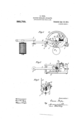
In the drawings Figures 1, 2 and 3 are respectively side, plan and end views of an apparatus embodying my invention, the magnets and sounder being omitted in views 2 and 3; Figs. 4, 5 and 6 are respectively plan, side and end views of a modified form of my apparatus, the sounder and magnets being omitted from Figs. 5 and 6, and the dial from Fig. 4 and part of the frame being broken away in Fig. 6; and Fig. 7 illustrates, diagrammatically, the operation of my invention.
Similar letters and reference designate corresponding parts in all the figures.
The frame 1, which may be provided with means, as for instance the hook 2 and setscrew 3, for detachably securing it to the posts 4 4 of a clock frame, or may be otherwise supported upon a clock or other motor frame, has a rocking bar 5 mounted therein upon a pivot 6. This rocking bar 5 is so adjusted that the free end of it will be depressed by the downward movement of the sounder 7 operating upon the set-screws 8, as in Figs. 1 and 2, or upon the angle plate 0, as shown in Figs. 4, 5 and 6, which angle plate is vertically adjust-able upon the rocking bar 5 by means of the adjusting screw 10 threaded into the angle plate 9 and resting upon the top of the rocking bar 5; and the rocking bar 5 is counterbalanced so that its outer end will rise when not depressed by the sounder 7.
The inner end of the rocking bar 5 is forked so as to provide suitable bearings for the shaft 11 which carries a toothed wheel or segment of a wheel 12, which is adapted to drop into contact with an intermediate gear 13 rotated through the pinion 14 by the drive wheel 15, as shown in Fig. 1, or directly into contact with the drive wheel 15, as shown in Fig. 5. This drive wheel 15 may conveniently be the seconds wheels of a clock, revolving from left to right; and in the construction shown in Fig. 1 the toothed segment will be rotated in the same direction as the drive wheel while in the construction shown in Fig. 5 it will be rotated in the opposite direction, or from right to left. The shaft 11 carries a pointer 16 which travels around the dial 17; and the shaft 11 also carries contact points which may be in the form of adjustable arms mounted thereon as 18.19 and 20, or may be screws or studs as 18, 19 and 20 detachably inserted in the series of round holes or sockets shown near the circumference of a disk 22, in either case the result being that the shaft 11 carries contact points which may be adjusted relative to each other and relative to the pointer 16. The contact point 19 or 19 is insulated while the points 18 and 20 or 18 and 20 are not.
Insulated upon the frame 1 is the contact point 23 to which is connected the wire 24, and this contact point may be rigid and vertically adjustable by means of the set screws 25 25, as shown in Figs. 1, 2 and 3, or it may be in the form of a spring plate, as shown in Figs. 4, 5 and 6, also adjustable by means of the set screw 25 threaded through it and bearing on the insulation below it.
The operation of the apparatus is as follows :-If the line is not being used and the circuit is closed, the sounder depresses the outer end of the rocker bar 5, and the pointer 16 remains in its initial position as shown in Figs. 1 to 6 of the drawings, the shaft and its attachments being counterbalanced so that the pointer will swing back to that position when free to do so. If a message is being transmitted over the wire, the rapid movements of the sounder are repeated by the rocking bar 5, and the pointer will have a rapid vibratory movement, due to its intermittent contact with the drive wheel which starts it forward when in contact and allows it to drop back when freed. The space upon the dial which is traversed by the pointer in these vibrations is not used for signaling, and is illustrated by the unmarked space on the left of the dial in Fig. 1. If an oflice is to be group.
called the operator at the calling station i station opens the circuit and the selectors at opens the circuit with his key 26, which raises all the sounders 7 7 on the circuit, permitting the wheel or segment 12 to fall into contact with the driving gear, all the shafts 11 11 turning in unison and their pointers 16 passing over corresponding portions of their dials. The contact points 20 or 2O however are set at different positions for the different otiices, so that each contact point will be under the point 23 of its station when the pointer covers the dial number of that station. Each station may, therefore, be designated by the number on the dial corresponding to the position of its contact point. lVhen the pointer covers the dial number of the station wanted the operator closes his key, and the sounders 7 7 at all the stations press against the outer ends of the rocking bars 5, raising their inner, forked ends and freeing the wheel or segment 12 from the driving gear, allowing the pointers at all stations except the called station to fall back to their initial position. The contact point 20 or 20 however, of the called station being directly beneath the contact point 23 is pressed up against it, closing the local circuit through the bell or buzzer 27 which is arranged to ring continuously on a closed circuit. The same contact also closes the circuit of the sounder and keeps it closed, thereby holding 20 and 23 together and continuing the operating of the alarm at the called station until the attendant by opening a switch as 29 breaks the local circuit of the sounder independently of the position of the relay points which normally operate it.
Where there are a large number of stations on a line and it is desired to provide each with a selective call, they may be divided into groups, each office in a group having a distinctive number. In that case the group contact 19 or 19 is called into use. This group contact is insulated and is placed ahead of the contact 20 or 20*, and has the same position at all stations in its Thus the three stations shown in Fig. 7 represent stations in three different groups, the first to the left belonging to group A, the next, which is a way station having no main battery, to group F, and the next to group K; the individual station contacts 20 being also differently positioned at each station. The index dials are shown as numbered consecutively, so as to be used for one large group of stations, and also as havin the first five numbers IUl TOUDQCl f! b i for individual calls, and the remaining spaces lettered for groups, so that each let ter group may have five individual stations therein. Of course these numbers may be varied.
The circuit being closed the pointers are all at their initial positions. The calling all the stations revolve in unison. When the pointer reaches the letter of the group wanted the calling station closes the circuit and the group contact 19 or 19 is pressed against the contact point 23 at all the stations in that group and is held there, against retrogression from its advanced position, by its upward pressure against the contact point 23, all the other stations, including the calling station, unless it is calling its own group, missing contact and their selector apparatus returning to the initial position. \Vith the selectors of the desired group in their advanced positions as above, the calling oflice again opens the circuit, the selector gear drops into contact with the actuating gear, and the pointers are again moved forward, the selectors in the desired group proceeding from their advanced positions, and when the pointer reaches the figure of the stat-ion called the circuit is again closed and the selector 20 of the called otlice meets the contact point 23, completing the circuit and ringing the bell at the called oliice, as already described, the other stations in the group failing to make contact and being released, their group contact points 19 or 19*, being held up by closed circuits so as 110-t to encounter the stationary contact point 23, but passing over it and returning to their initial positions. If a station is calling another in its own group it is not released when the group contact is made as its group contact as well as the other group contacts in the same group will be held in their advanced position, as above described, and, on again opening the circuit, its pointer proceeds from its advanced position until the number of the called office is reached.
7 If the circuit on the line is opened by accident the pointers at all the stations move forward until the warning contact 18 comes into contact with 30 (or, in the form shown in Figs. 4 to (3, 18 contacts with the end of 23), and closes the circuit through bell and sounder. There being no'lock provided in case of this contact the closing of the sounders operates the rocking bars 5 breaking the local circuit, and the contact is again made and the operation repeated. This gives a distinctive signal at every station so that the attention of the operators is called to test and report to the terminal office. It also prevents the stoppage of the clock train, which is important.
To use this calling system on an open circuit, such as a telephone line, the rocking bar 5 is reversed and contact is made with the driving wheel by the closing of the circuit instead of by its opening.
It will be understood that special clock work and special magnets may be used instead of the ordinary clock and receiving sounder mentioned above; which, however, are convenient means for operating my apparatus.
Having thus described my invention, what I claim and desire to secure by Letters Patent of the United States is 1. The combination, with an electric circuit, of a plurality of groups of signaling stations each station being provided with a station-contact selector and a group-contact selector, mechanism for synchronously moving all such selectors, means cooperating with said group-contact selectors for separating one group of stations from the others, said group-contact selectors being differently positioned relative to their cooperating means, and means for arbitrarily connecting or disconnecting such selectors and mechanism.
2. The combination, with an electric circuit, of a plurality of signaling stations each provided with vibratable bearings, an adjustable, rotary, contact selector mounted therein and a gear moving with said selector, mechanism embodying a continuously moving clock train whereby each selector is moved synchronously with the others, and
means for arbitrarily making or breaking connection between such gear and clock train by vibrating the contact-carrying bearings.
3. The combination, with an electric circuit, of a plurality of signaling stations each provided with a pivoted frame having a vibrating end provided with bearings therein, an adjustable, independently positioned, rotary, cont-act selector, mounted in said. bearings in the pivoted frame, and a gear moving therewith, mechanism embodying a.
continuously moving clock train whereby each selector is moved synchronously with the others, and means for arbitrarily making or breaking connection between such gear and clock train by vibrating the contact-carrying bearings.
4. The combination, with an electric current, of a plurality of signaling stations each provided with vibratable bearings, a rotary, contact selector mounted therein, an index finger and a gear moving with said selector, an index dial with which said index finger cooperates,mechanism embodying a continuously moving clock train whereby each selector is moved synchronously with the others, and means consisting of an armature engaging with said vibratable frame for arbitrarily making or breaking connection between such gear and clock train by vibrating the contact-carrying bearings.
5. The combination, with an electric circuit, of a plurality of signaling stations each provided with vibratable bearings, an adjustable, rotary, contact selector mounted therein, an index finger and a gear moving with said selector, an index (11211 with which such index finger cooperates, mechanism embodying a continuously moving clock train whereby each selector is moved synchronously with the others, and means for arbitrarily making or breaking connection between such gear and clock train by vibrating the contact-carrying bearings. I
6. The combination, with an electric circuit, of a plurality of signaling stations each provided with vibratable bearings, an independently-positioned, rotary, contact selector mounted therein, an index finger and a gear moving with said selector, an index dial with which such index finger cooperates, mechanism embodyinga continuously moving clock train whereby each selector is moved synchronously with the others, and means for arbitrarily making or breaking connection between such gear andclock train by vibrating the contact-carrying bearings.
7. The combination, with an electric circuit, of a plurality of signaling stations each provided with vibratable bearings, a rotary, station-contact selector and an insulated group-selector mounted therein, a gear moving with said selectors, mechanism embodying a continuously moving clock train whereby each selector is moved synchronously with the others, and means for arbitrarily making or breaking connection between such gear and clock train by vibrating the contact-carrying bearings.
8. The combination, with an electric circuit, of a plurality of signaling stations each provided with vibratable bearings, a rotary, stationcontact selector and an insulated group select-or mounted in said vibratable bearings, an index finger, and a gear moving with said selectors, an index dial with which such index finger cooperates, mechanism embodying a continuously moving clock train whereby each selector is moved synchronously with the others, and means for arbitrarily making or breaking connection between such gear and clock train by vibrating the contact-carrying bearings.
9. The combination, with an electric circuit, of a plurality of signaling stations each provided with a vibratable frame provided with bearings, a rotary, station-contact selector and an insulated group -selector mounted in said bearings, an index finger and a gear moving with said selectors, an index dial with which such index finger cooperates, mechanism embodying a continuously moving clock train whereby each selector is moved synchronously with the others, and means consisting of an armature engaging with said vibratable frame for arbitrarily making or breaking connection between such gear and clock train by vibrating the contact-carrying bearings.
10.'The combination, with an electric circuit, of a plurality of signaling stations each provided with a clock frame with a continuously moving clock train therein, a frame adapted to be detachably attached to said clock frame, an index dial mounted upon said detachable frame, a rocking bar pivoted in said frame, a sounder armature adapted to rock said rocking bar, a magnet to operate said sounder armature, rotary, selector mechanism embodying a station selector and an insulated group selector, an alarm contact, an index finger and a rotary gear moving therewith and adapted to be thrown into or out of contact with the clock train by the rocking of said bar.
11. The combination, with an electric circuit, of a plurality of signaling stations divided into groups, each station in any group being provided with a rotary, insulated, group selector, angularly positioned the same as all the others of that group, and with a rotary, station selector having an angular position different from the others, mechanism for synchronously rotating all such selectors, means for arresting and holding all the selectors in any group and releasing the others, and means for then operating the station selectors to select an individual station in said group to the exclusion of the others.
12. The combination, with an electric circuit, of a plurality of signaling stations divided into groups, each station in any group being provided with a rotary, insulated, group selector, angularly positioned the same as all the others of that group, and with a rotary, station selector having an angular position different from the others, and with a selector stop, mechanism for synchronously rotating all such selectors, means for arresting and holding all the selectors in any group, by bringing their group selectors in contact with their stops, to the exclusion of the others, and means for then operating the station selectors to select anindividual station in said group by freeing and moving forward such group selectors to the exclusion of the others.
13. The combination, in an electric signaling apparatus, of a frame having an insulated contact-point thereupon, a rocking bar mounted in the inner end of said frame and carrying a plate provided with circumferentially adjustable contact-stops, a continuously moving clock train, means for rotating said plate by bringing it under the influence of said continuously moving clock train through the lowering of the inner end of said rocking bar, and means for bringing said contact-stops against said insulated contact-point by raising the inner end of said rocking bar.
14. The combination, with an electric circuit, of a plurality of signaling stations each provided with an insulated contact-point and an adjustable and rotatable contact-stop having a different angular position from all the others, means for rotating all of said contact-stops in unison and means for raising them all simultaneously at right angles to their axes of rotation.
15. The combination, with an electric circuit, of a plurality of signaling stations each provided with an insulated contact-point and a rotatable contact-stop having a different angular position from all the others, means for rotating all of said contact-stops in unison and means for raising them all 7 simultaneously at right angles to the axes of rotation.
16. The combination, with an electric circuit, of a plurality of signaling stations each provided with continuously moving propelling mechanism and with selective apparatus having a bias toward an initial position and adapted to be actuated by said propelling mechanism and having a selective circuit closer and means actuated thereby and also an alarm contact closer for automatically releasing such selective apparatus from contact with such propelling mechanism and permitting it automatically to return to its initial position.
EDWIN POPE. Witnesses DAVID R. MoVVILLIAMs, J AMES BARCLAY.
Copies of this patent may be obtained for five cents each, by addressingthe Commissioner of Patents. Washington, I). G.
Priority Applications (1)
| Application Number | Priority Date | Filing Date | Title |
|---|---|---|---|
| US48024009A US989799A (en) | 1909-02-26 | 1909-02-26 | Electric signaling apparatus. |
Applications Claiming Priority (1)
| Application Number | Priority Date | Filing Date | Title |
|---|---|---|---|
| US48024009A US989799A (en) | 1909-02-26 | 1909-02-26 | Electric signaling apparatus. |
Publications (1)
| Publication Number | Publication Date |
|---|---|
| US989799A true US989799A (en) | 1911-04-18 |
Family
ID=3058137
Family Applications (1)
| Application Number | Title | Priority Date | Filing Date |
|---|---|---|---|
| US48024009A Expired - Lifetime US989799A (en) | 1909-02-26 | 1909-02-26 | Electric signaling apparatus. |
Country Status (1)
| Country | Link |
|---|---|
| US (1) | US989799A (en) |
-
1909
- 1909-02-26 US US48024009A patent/US989799A/en not_active Expired - Lifetime
Similar Documents
| Publication | Publication Date | Title |
|---|---|---|
| US989799A (en) | Electric signaling apparatus. | |
| US359686A (en) | notes | |
| US573924A (en) | Fire-alarm system | |
| US1051148A (en) | Selective signaling system. | |
| US472983A (en) | chase | |
| US236257A (en) | Automatic time-register and alarm | |
| US512400A (en) | scribner | |
| US452026A (en) | Charles j | |
| US1294928A (en) | Train-despatching system. | |
| US1079467A (en) | Search-call apparatus. | |
| US1217241A (en) | Alarm signaling apparatus. | |
| US288449A (en) | kinsman | |
| US254573A (en) | Individual signaling apparatus for telephone-lines | |
| US1306074A (en) | Signaling system | |
| US283736A (en) | William sohuylee johnson | |
| US244382A (en) | Signal-operating device for telephone-circuits | |
| US694977A (en) | Electric switch. | |
| US235424A (en) | frankenbera | |
| US336002A (en) | Telephone-call-bell system | |
| US998299A (en) | Electric signaling system. | |
| US264264A (en) | Electrical signaling apparatus | |
| US695991A (en) | Electric signaling and circuit-controlling apparatus. | |
| US598172A (en) | barron | |
| US212792A (en) | Improvement in electric signaling apparatus | |
| US447045A (en) | ginochio |