US989492A - Mail-carrying device. - Google Patents
Mail-carrying device. Download PDFInfo
- Publication number
- US989492A US989492A US55444610A US1910554446A US989492A US 989492 A US989492 A US 989492A US 55444610 A US55444610 A US 55444610A US 1910554446 A US1910554446 A US 1910554446A US 989492 A US989492 A US 989492A
- Authority
- US
- United States
- Prior art keywords
- posts
- post
- delivery
- box
- Prior art date
- Legal status (The legal status is an assumption and is not a legal conclusion. Google has not performed a legal analysis and makes no representation as to the accuracy of the status listed.)
- Expired - Lifetime
Links
- 244000261422 Lysimachia clethroides Species 0.000 description 3
- 230000005484 gravity Effects 0.000 description 3
- 230000010006 flight Effects 0.000 description 2
- 238000007665 sagging Methods 0.000 description 2
- 244000186140 Asperula odorata Species 0.000 description 1
- 235000008526 Galium odoratum Nutrition 0.000 description 1
- 238000010276 construction Methods 0.000 description 1
- 230000006872 improvement Effects 0.000 description 1
- 230000002459 sustained effect Effects 0.000 description 1
- 210000001364 upper extremity Anatomy 0.000 description 1
Images
Classifications
-
- B—PERFORMING OPERATIONS; TRANSPORTING
- B61—RAILWAYS
- B61B—RAILWAY SYSTEMS; EQUIPMENT THEREFOR NOT OTHERWISE PROVIDED FOR
- B61B9/00—Tramway or funicular systems with rigid track and cable traction
Definitions
- This invention relates to a delivery boX service, and isespecially adapted to convey mail boxes to and from a dwelling to the road over which the mail carrier or mes senger ona rural delivery route passes.
- One of the objects of the invention is to provide a device of the characterdescribed which will be economical, effective, simple and durable and which maybe erected over fields without offering any undue impediment to the working of the field and absolutely no impediment tothe'working of the device.
- a still further object of the invention is to'p'rovide aconveyer of this'class wherein the device may be raised as it reaches each post" over which the trolley and traveling wires ofthe 100K pass to allow the box to descend by gravity at leasthalfof the length of the trolley between two of the posts.
- th invention resides in the novel construction and combination of parts'hereina-fter fully described and claimed.
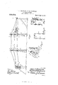
- Figure '1 is a perspective view of the improved device.
- Fig. 2 is a detail view of the mechanism provided forupon one of the posts D.
- Fig. 3 is'an elevation of the posts forming the delivery end of the device.
- Fig. 4. is a similar view of the receiving end of the device.
- the device contemplates the employment of end supports or stations and intermediate posts.
- the end supports are 'positioned adjacent what may be termed the delivering station or the point where the mail is placed within or collected from a suitable traveling box or receptacle and forwarded to the opposite post, which is located at the receiving station.
- the posts adjacent the delivering station comprise a pair of upright members designated by the letters A and A. These posts are connected through the medium of a suitable bar as clearly illustrated in Fig. 3
- the posts are each further provided with angularly arranged braces C.
- the receiving station also comprises a pair of vertical posts Band B, the same being arranged ih'spaced relation to each other and being suitably connected at their tops.
- the said posts are also provided with brace members C so that both the delivery and receiving stations are sustained effectively rigid.
- the letter D designates the intermediate posts. Any number of the said'posts D may be employed, and each of these posts is of a greater height than that of the receiving or delivery stations.
- the posts D are arranged a suitable distance away from each other and away from the stations.
- the postsD are each provided with upper and lower right angularly arranged arms 2 and 3.
- Thearms 2 are adapted to support asubstan'tially J-shap'ed bracket 15.
- the straight arm of the said bracket projects a suitable distance above the offset or arm 2 and is bent upon itself as at 17 to provide a housing or support for a pulley 4c.
- an outwardly curved member 16 Secured to the said housing and to thelower' arm 3 of the post D is an outwardly curved member 16, the lower portion of which being straight to provide for the" pivotal connection therewith'of'a pulley 5, the opposite end of the said pulley being supported in the vertically disposed portion of an angularly arranged member 18, the same having its upper eX tremity connected with the post D.
- the numeral 1 designates a trolley wire; This wire is'secured to both the receiving and 'deliverystat-ions and is connected with the lower or offset portion of the J-shaped brackets 15.
- the members, comprising the receiving post have rotatably mounted therebetween a sheave wheel 6 and the delivery station is also provided with a similar pivotedsheave wheel 7.
- the numeral 8 designates an endless cable, the same adapted to be received within the sheave wheels'6 and 7 and to also engage with the pulleys at and 5 upon the posts D.
- a toothed wheel 9 Connected with the shaft of the sheave wheel 6 is a toothed wheel 9, the latter adapted to cooperate with a larger toothed Wheel 10.
- This toothed wheel 10 is pivotally connected to one of the posts of the receiving station and the said wheel is provided with a handle 11.
- the numeral 12 designates the traveling box or conveyer.
- the box is provided with a suitable door whereby mail or other matter may be positioned therein or removed therefrom. It is to be understood, of course, that the door is provided with a suitable-lock and that access to the box cannot be obtained by other than those holding the proper key.
- the box 12 has its outer side connected in any desired manner to the lower flight 13 of the endless cable 8.
- a pair of upstanding members 14 Connected to the top of the box adjacent the-opposite ends thereof is a pair of upstanding members 14, the same having their upper extremities bent in the form of a gooseneck, and between the said members 18 and the gooseneck thereof are pivotally connected suitable guide wheels 20, the latter being adapted to travel upon the trolley wire 1 when the endless cable is operated.
- the said conveyer passes the post D it will, owing to its weight, travel by gravity a distance substantially equaling half of the length of the cable and trolley wire between the first and second posts D, and this operation is continued until the box reaches the last intermediate post D.
- the trolley wire as well as the flights of the endless cable are inclined over the posts D toward both the delivery and receiving station and by this arrangement the box 12 will travel farther by gravity upon the inclined trolley wire toward either the delivery or receiving stations.
- a trolley wire connecting all of the posts, said trolley wire being arranged at an angle from the delivery and receiving posts to the intermediate posts and having its central portion between the intermediate posts sagging, a carrier, rollers upon the carrier mounted upon the trolley wire, said carrier having a connection with the lower flight of the endless conveyer, and
- I11 a device for the purpose set forth, a delivery post, a pulley upon the post, a handle for rotating the pulley, a delivery post a pulley for the delivery post, an end less cable connecting the pulleys of both of these posts, intermediate posts of greater height than the first named posts, offset spaced arms upon the intermediate posts, pulleys upon these offset arms adapted to be engaged by the endless conveyer, J-shaped members connected with the upper arms of each of the intermediate posts, a cable connected wit-h the end posts and with the J- shaped members of the intermediate posts, said cable being taut between the end intermediate posts and the end posts, a yoke member connecting the pulleys upon the arms, a yoke continuation between the pulleys and the posts and arranged at an inclination thereto, a carrier having its top provided with spaced pulleys adapted to be positioned upon the cable, and a connection between the lower flight of the endless conveyer and the carrier.
Landscapes
- Engineering & Computer Science (AREA)
- Transportation (AREA)
- Mechanical Engineering (AREA)
- Handcart (AREA)
Description
J. P. ERIGKSON (Ya M. M. WOODWARD.
MAIL CARRYING DEVICE. APPLICATION IILED APR.9, 1910.
Patented Apr. 11, 1911 Emma/tow $022,
IHE Noam; PETERS cm, wnswnvcrcu, 0. c4
JOHN ERIGKSON' AND MILTON M. WOODWARD; OF WILD ROSE, WISCONSIN.
MAIL-CARRYING Defies;
Specification of Letters Patent.
Application filed April 9,
Patented Apr. 11, 1911. 1910. Serial as; 554,446:
To all whom itm aycomer n):
Be it kn'owi that we, J OHN F. ERIOKSON and MILTON M. oonwmn, citizens of the United States, residing at Wild Rose, in the county of Vva'ushara and State of \Visconsin, have invented new and useful Improve ments in Mail Garrying Devices, of which the following is a specification.
This invention relates to a delivery boX service, and isespecially adapted to convey mail boxes to and from a dwelling to the road over which the mail carrier or mes senger ona rural delivery route passes.
One of the objects of the invention is to provide a device of the characterdescribed which will be economical, effective, simple and durable and which maybe erected over fields without offering any undue impediment to the working of the field and absolutely no impediment tothe'working of the device.
A still further object of the invention is to'p'rovide aconveyer of this'class wherein the device may be raised as it reaches each post" over which the trolley and traveling wires ofthe 100K pass to allow the box to descend by gravity at leasthalfof the length of the trolley between two of the posts.
with the above, and other objects in view, which will appear as the description progresses, th invention resides in the novel construction and combination of parts'hereina-fter fully described and claimed.
In the accompanying drawings there has been illustrated a simple and preferred form of the device, and in which drawings,
Figure '1 is a perspective view of the improved device. Fig. 2 is a detail view of the mechanism provided forupon one of the posts D. Fig. 3 is'an elevation of the posts forming the delivery end of the device. Fig. 4. is a similar view of the receiving end of the device.
The device contemplates the employment of end supports or stations and intermediate posts. The end supports are 'positioned adjacent what may be termed the delivering station or the point where the mail is placed within or collected from a suitable traveling box or receptacle and forwarded to the opposite post, which is located at the receiving station. The posts adjacent the delivering station comprise a pair of upright members designated by the letters A and A. These posts are connected through the medium of a suitable bar as clearly illustrated in Fig. 3
of the drawings. The posts are each further provided with angularly arranged braces C. The receiving station also comprises a pair of vertical posts Band B, the same being arranged ih'spaced relation to each other and being suitably connected at their tops. The said posts are also provided with brace members C so that both the delivery and receiving stations are sustained effectively rigid.
The letter D designates the intermediate posts. Any number of the said'posts D may be employed, and each of these posts is of a greater height than that of the receiving or delivery stations. The posts D are arranged a suitable distance away from each other and away from the stations. The postsD are each provided with upper and lower right angularly arranged arms 2 and 3. Thearms 2 are adapted to support asubstan'tially J-shap'ed bracket 15. The straight arm of the said bracket projects a suitable distance above the offset or arm 2 and is bent upon itself as at 17 to provide a housing or support for a pulley 4c. Secured to the said housing and to thelower' arm 3 of the post D is an outwardly curved member 16, the lower portion of which being straight to provide for the" pivotal connection therewith'of'a pulley 5, the opposite end of the said pulley being supported in the vertically disposed portion of an angularly arranged member 18, the same having its upper eX tremity connected with the post D.
The numeral 1 designates a trolley wire; This wire is'secured to both the receiving and 'deliverystat-ions and is connected with the lower or offset portion of the J-shaped brackets 15. The members, comprising the receiving post have rotatably mounted therebetween a sheave wheel 6 and the delivery station is also provided with a similar pivotedsheave wheel 7.
The numeral 8 designates an endless cable, the same adapted to be received within the sheave wheels'6 and 7 and to also engage with the pulleys at and 5 upon the posts D. Connected with the shaft of the sheave wheel 6 is a toothed wheel 9, the latter adapted to cooperate with a larger toothed Wheel 10. This toothed wheel 10 is pivotally connected to one of the posts of the receiving station and the said wheel is provided with a handle 11.
The numeral 12 designates the traveling box or conveyer. The box is provided with a suitable door whereby mail or other matter may be positioned therein or removed therefrom. It is to be understood, of course, that the door is provided with a suitable-lock and that access to the box cannot be obtained by other than those holding the proper key. The box 12 has its outer side connected in any desired manner to the lower flight 13 of the endless cable 8. Connected to the top of the box adjacent the-opposite ends thereof is a pair of upstanding members 14, the same having their upper extremities bent in the form of a gooseneck, and between the said members 18 and the gooseneck thereof are pivotally connected suitable guide wheels 20, the latter being adapted to travel upon the trolley wire 1 when the endless cable is operated.
From the above description taken in connection with the accompanying drawings, it will be noted that the goosenecks of the members 14; effectively sustain the guide wheels 20 upon the trolley wire 1. It will be further noted by reference to Fig. 1 of the drawings, that the trolley wire 1 between the posts D as well as the lower flight 13 of the endless cable are sufficiently slack to allow both of the said elements to be of a substantially bow shape and it will be noted that when the toothed wheel 10 is rotated, the box or conveyer 12 will be lifted from, say the receiving station, to the first post D. hen the said conveyer passes the post D it will, owing to its weight, travel by gravity a distance substantially equaling half of the length of the cable and trolley wire between the first and second posts D, and this operation is continued until the box reaches the last intermediate post D. The trolley wire as well as the flights of the endless cable are inclined over the posts D toward both the delivery and receiving station and by this arrangement the box 12 will travel farther by gravity upon the inclined trolley wire toward either the delivery or receiving stations. It is, of course, obvious that the handle 11 is at all times operated, but it will be apparent that the exertion of the operator is reduced to a minimum.
Having thus fully described the invention, what we claim as new is 1. In a device for the purpose set forth, a
'flights sagging toward their centers between the intermediate posts, a trolley wire connecting all of the posts, said trolley wire being arranged at an angle from the delivery and receiving posts to the intermediate posts and having its central portion between the intermediate posts sagging, a carrier, rollers upon the carrier mounted upon the trolley wire, said carrier having a connection with the lower flight of the endless conveyer, and
means for moving the conveyer.
2. I11 a device for the purpose set forth, a delivery post, a pulley upon the post, a handle for rotating the pulley, a delivery post a pulley for the delivery post, an end less cable connecting the pulleys of both of these posts, intermediate posts of greater height than the first named posts, offset spaced arms upon the intermediate posts, pulleys upon these offset arms adapted to be engaged by the endless conveyer, J-shaped members connected with the upper arms of each of the intermediate posts, a cable connected wit-h the end posts and with the J- shaped members of the intermediate posts, said cable being taut between the end intermediate posts and the end posts, a yoke member connecting the pulleys upon the arms, a yoke continuation between the pulleys and the posts and arranged at an inclination thereto, a carrier having its top provided with spaced pulleys adapted to be positioned upon the cable, and a connection between the lower flight of the endless conveyer and the carrier.
In testimony whereof we afiix our signatures in presence of two witnesses.
JOHN F. ERIOKSON. MILTON M. WOODVVARD. lVitnesses J OHN V. BERENS, CLYDE DIGGLES.
( t-pies of this patent may be obtained for five cents each, by addressing the Commissioner of Patents,
Washington, D. G. v
Priority Applications (1)
| Application Number | Priority Date | Filing Date | Title |
|---|---|---|---|
| US55444610A US989492A (en) | 1910-04-09 | 1910-04-09 | Mail-carrying device. |
Applications Claiming Priority (1)
| Application Number | Priority Date | Filing Date | Title |
|---|---|---|---|
| US55444610A US989492A (en) | 1910-04-09 | 1910-04-09 | Mail-carrying device. |
Publications (1)
| Publication Number | Publication Date |
|---|---|
| US989492A true US989492A (en) | 1911-04-11 |
Family
ID=3057830
Family Applications (1)
| Application Number | Title | Priority Date | Filing Date |
|---|---|---|---|
| US55444610A Expired - Lifetime US989492A (en) | 1910-04-09 | 1910-04-09 | Mail-carrying device. |
Country Status (1)
| Country | Link |
|---|---|
| US (1) | US989492A (en) |
-
1910
- 1910-04-09 US US55444610A patent/US989492A/en not_active Expired - Lifetime
Similar Documents
| Publication | Publication Date | Title |
|---|---|---|
| US989492A (en) | Mail-carrying device. | |
| US553109A (en) | Alexander ii | |
| US917428A (en) | Portable rural mail-box. | |
| US811991A (en) | Cable conveyer. | |
| US1022325A (en) | Harvester attachment. | |
| US986011A (en) | Rural-mail-delivery device. | |
| US705440A (en) | Apparatus for carrying mail-matter. | |
| US846313A (en) | Mail-transportation system. | |
| US844125A (en) | Mail-delivery apparatus. | |
| US906598A (en) | Mail-delivery. | |
| US985991A (en) | Loader for corn-binders. | |
| US878653A (en) | Trolley-pulley. | |
| US783920A (en) | Mail or package transmitter. | |
| US883067A (en) | Mail-conveyer. | |
| US859670A (en) | Wire-rope-transmission device. | |
| US954554A (en) | Mail-carrier. | |
| US927489A (en) | Rural-mail carrier. | |
| US674870A (en) | Manure-carrier. | |
| US853976A (en) | Conveying apparatus. | |
| US479502A (en) | Store-service apparatus | |
| US990491A (en) | Carton-sealing machine. | |
| US971914A (en) | Mail delivering and collecting apparatus. | |
| US781896A (en) | Store-service apparatus. | |
| US1283656A (en) | Device for repairing cars. | |
| US546599A (en) | Mail-bag catcher |