US989458A - Electric-circuit breaker. - Google Patents
Electric-circuit breaker. Download PDFInfo
- Publication number
- US989458A US989458A US48166309A US1909481663A US989458A US 989458 A US989458 A US 989458A US 48166309 A US48166309 A US 48166309A US 1909481663 A US1909481663 A US 1909481663A US 989458 A US989458 A US 989458A
- Authority
- US
- United States
- Prior art keywords
- spring
- spindle
- secured
- switch
- contact
- Prior art date
- Legal status (The legal status is an assumption and is not a legal conclusion. Google has not performed a legal analysis and makes no representation as to the accuracy of the status listed.)
- Expired - Lifetime
Links
Images
Classifications
-
- H—ELECTRICITY
- H01—ELECTRIC ELEMENTS
- H01H—ELECTRIC SWITCHES; RELAYS; SELECTORS; EMERGENCY PROTECTIVE DEVICES
- H01H3/00—Mechanisms for operating contacts
- H01H3/32—Driving mechanisms, i.e. for transmitting driving force to the contacts
- H01H3/50—Driving mechanisms, i.e. for transmitting driving force to the contacts with indexing or locating means, e.g. indexing by ball and spring
- H01H3/503—Driving mechanisms, i.e. for transmitting driving force to the contacts with indexing or locating means, e.g. indexing by ball and spring making use of electromagnets
Definitions
- the invention consists essentially in the novel construction and arrangement of parts, whereby a spring actuated electrical contact is held to a closed position by a spring held latch mechanism and said latch mechanism is released by suitable means.
- the objects of the invention are, to obviate the difficulties incident to the fusing of the contacts through arcing, to break the ⁇ contacts quickly and eifectively and increase the air gap as fastas possible so as to minimixe the arcing, to construct a circuit breaker wherein the actuating parts are thoroughly insulated from the contact parts and which cannot be affected by arcing between the parts, and generally to provide an eflicient form of circuit breaker which in its detailed construction may be readily adapted to cut out a plurality of electric circuits simultaneously.
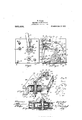
- Figure 1 is an outside plan View of one side of the circuit breaker.
- Fig. 2 is a plan view of the circuit breaker, the cover being removed and disclosing the arrangement of the interior mechanism.
- Fig. 8 is a perspective view of the device shown partly in section and showing the latch mechanism, the view being the reverse of the view shown in Fig. 1.
- Fig. 4 is a horizontal sectional view through the line A-B Fig. 2.
- Fig. 5 is a diagrammatic view showing the wiring to the circuitbreaker.
- FIG. 1 and 2 are plates, preferably of iron, forming the outer sides or casing of the circuit breaker and each having the circular orifices 3 oppositely arranged one to the other and near the center and the orifices 4 oppositely arranged one to the other near the bottom edge and the laterally extending fastening lugs 5 at said bottom edge.
- G are plates of insulating material suitably secured to the inner side of the plates l and 2, each having the circular orifices 7 of smaller' diameter than the orifices 3 and centrally arranged in relation thereto, and the orifices 8 of the same size as the orifices 4 and oppositely arranged thereto.
- 9, 10, 11 and 12 are strips of insulating material extending between the plates 6 and holding said plates apart, the strips 9, 10 and 11 being held in place by the bolts 13, 14 and 15 extending therethrough, said bolts being secured by suitable nuts secured to their outwardly projecting threaded ends.
- the strip 12 is secured to the strip 9 with suitable screws and is provided with antician 16 toward its upper end and a bolt hole therethrough below the strip 9.
- 17 is a terminal fiXedly secured to the strip 9 and having an orifice 18 therein arranged opposite to the orifice 16 in the plate 12 and a suitable binding screw 19 for securing the end of one of the wires leading to the circuit breaker in the orifice in said terminal.
- 2O is a spring contact arm secured to the terminal 17 and having the contact piece 21 at the outer end thereof and the set screw 22 threaded therein intermediate of its length, said screw being adapted to engage the upper surface of the strip 9 and having a suitable lock nut thereon.
- rotary switch 32 is a rotary switch formed of a substantially segmental shaped piece of insulating material ixedly secured to the flange 29 on the spindle 27 and having the contact surface portion 33 of conducting material rigidly secured thereto and adapted to contact with the contact pieces 21 and 25 of the arms 2O and 24 respectively.
- notch 34 is a notch formed in the rotary switch 32 adjacent to one end of the arc-shaped contact portion 33, one side of said notch forming a shoulder 35.
- rocker arm 41 is a rocker arm pivotally supported on the bolt L10 and having the ltr-shaped contact piece 12 rigidly secured at one end thereof and adapted to engage the contact- 39.
- the other end 113 ot the rocker arm stl extends into the notch 34 in the rotary switch 32 and said arm is spring held with the contact L12 in engagement with the contact 39 by a spiral tension sning 44tsecured to said arm and to a suitable bolt l5 secured in the bolt hole in the insulating strip 12.
- -itt is a ratchet disk formed ot insulating material. loosely mounted on one of the extending ends of the spindle 27 and abutting the tace of the plate 1.
- 117 is a pawl mounted on the screw secured in the plate 1 and engaging the teeth et' said ratchet disk.
- i-9 is a lever handle having a squared oriltice 50 through which the squared end 30 of the spindle 27 extends.
- the spring 51 is a spiral spring having one end secured to the ratchet disk t6 and t-he other end secured to the lever 49.
- the spring 51 is arranged so .that when the contact portion of the switch 32 is in engagement with the contact pieces 21 and 25 of the arms 20 and 24. the said spring will be in tension and will7 on the release of the spindle, turn it to throw the contact piece 33 out of contact with the contact 25.
- the tension ot the spring may be regulated by turning the ratchet disk 16.
- rotary latch member 52 is a rotary latch member formed of a disk of insulating material secured to the squared end 31 of the spindle 27 and abutting the plate 27 said disk having a metal sector 53 iixedly secured to its outer tace, said rotary latch forming a portion ot the mechanism for holding the spring 51 in tension and the Contact 33 in engagement with the Contact arms 20 and 211.
- the extending end 4:3 ot the rocker arm t1 is so arranged in relation to the shoulder formed in the rotary switch 32, that the said shoulder engages the upper side of the said arm i13 simultaneously with the breaking of contact between the contact piece 25 on the arm 24 and the contact piece 33 on said switch7 consequently tilting the arin t0 on its pivot and causing the separation of the contacts 39 and L12, thus breaking both circuits leading to the circuit breaker simultaneously.
- rlhe shoulder strikes the arm 43 sharply and throws the contacts 39 and t1 out of engagement Very quickly and also a sutlicient distance to insure perfect insulation. Lt will therefore be readily seen that it both sets of contacts are arranged in the same electrical circuit, the air gap between the contacts will increase with much greater speed than when only one break is made.
- 5st is an electro-magnet arranged between the plates 6 surrounding the hollow core secured in said plates.
- One end of the winding et the electro-magnet is electrically connected to the terminal 23 and the other end leads to one ot the wires leading to the circuit breaker.
- 55 is a spindle extending through the hollow core ot the electro-nnignet 5st and having a head 5T formed on the end projecting beyond the plate 2 and threaded on the opposite end, said head having a tlattened. pin 5S projecting trom the top thereof.
- G1 are a pair ot lugs secured to or torining part with the plate 2 and projecting outwardly therefrom having suitable journal oriiiees centrally arranged therein.
- G2 is a spindle jourualed in the oritiecs in the lugs 61.
- 63 is a ratchet wheel tixedly secured to one end of the spindle G2.
- 611 is a spring dog secured to the plate 2 and engaging the ratchet wheel G3.
- G5 is a spring arm secured to the spindle ($2 and coiled thcrearound and extending outwardly therefrom and over the head ot the armature spindle 56, said spring having a longitudinal slot 6G through which the pin 53 extends.
- G7 is an arm pivotally supported at one end on the spindle (i2 and pivotally secured at its opposite end to the head 57 ot the armature spindle said arm having' the downwardly projecting lip G3 arranged intern'iediate ot' its length and adapted to engage the straight edge ot the sector 53.
- the tensionY et the spring arm ($5 may he adjusted by turning the spindle 62. said spindle being held in an adjusted position by the spring dog (34- engaging the teeth ott the ratchet wheel 63,
- the spring arm G5 holds the head of the armature spindle in engagement with the end ot the hollow core 55 ot' the electroniagnet 5l, consequently holding the armature 59 away from the said core.
- the armature being threaded on the armature spindle 56 may be adjusted very accurately, so that it may be set to operate with a certain predetermined current flowing through the coils of the magnet, that is to say, it may be set so that a certain strength of current may iiow through the magnet without attracting the armature but in the event ot the current exceeding the normal tlow, the armature will be attracted by the magnet and consequently operate the spindle 56 to raise the arm 67, withdrawing the lip 68 from engagement with the engaging edge of the sector 53.
- the spiral spring 51 rotates the spindle 27 in its bearings and turns the rotary switch 32 breaking the electrical connection between the terminals 17 and 9.3.
- the shoulder of the rotary switch 32 engages the extending end 43 oit' the rocker arm 41 and throws the contact pieces 39 and 42 out of contact, thus breaking the electrical connection between the terminals 36 and the terminal formed by the bolt- 40.
- the 69 is a wire leading from the electric current supply to the electro-magnet 54.
- the return wire 71 from the iields of the motor is connected to the bolt 40 and the current tlows through the contacts 42 and 39 to the terminal 36 and from said terminal 36 is carried through the wire 72 to the source otsupply. It will be seen that the electrical connection to the motor will be broken at two separate points and neither of the connections leading from the source of supply to the motor will be in contact when the circuit breaker is operated.
- What I claim as my invention is 1. 1n an electric circuit breaker, an electric switch closing an electric circuit and spring actuated to break said circuit, a spring held latch mechanism holding said switch in its closed position, an electro-inagnet included in said electric circuit and having a hollow core and an armature spindle extending through said core and an armature adjustably secured to said spindle, said armature spindle being operatively connected to said latch mechanism.
- an electric switch spring oscillated to break an electric circuit, a catch forming part of a latch mechanism and oscillating in a parallel plane to said switch and operating coincidently, an electro-magnet, a spindle extending through said magnet and parallel to said switch axis, an armature mounted toward one end of said spindle, an arm forming part of said latch mechanism extending across said latch and pivotally secured at both ends, one end to said spindle, and an adjustable spring connected to said spindle.
- an electric circuit breaker the combination with a suitable casing, of an oscillatory electric switch supported in said casing and closing an electric circuit and spring actuated to break said circuit, a latch member oscillating with said switch, a pivotal latch arm having a projecting lip adapted to engage said latch member and hold said oscillatory switch to its closed position, a spindle supported in suitable lugs extending from said casing, a ratchet disk tixedly secured to said spindle, a dog engaging said ratchet disk, a coiled spring tixedly secured to said spindle and extending outwardly therefrom and holding said latch arm in engagement with said latch member, and an electro-magnet having an armature operatively connected to said latch arm.
- an electric circuit breaker a pair ot electrical contacts suitably supported, an oscillatory switch formed of a piece of insulating material of substantially sector shape having a notch formed therein and an electric contact piece secured to its outer periphery adapted to engage said electrical con ⁇ tacts, spring means for operating said oscillatory switch to break the electrical connection between said contacts, a spring held latch mechanism holding said oscillatory switch against spring tension and in contact with said contacts, means for releasing said latch mechanism, a rocker arm pivotally supported and electrically connected to a wire leading to the circuit breaker and having an electric contact piece on one end thereotl and the other end extending into the notch formed in said oscillatory switch, an electric contact adapte-d to engage the contact piece en said rocker arni suitably supported and electricall7 connected to a suitable terminal, and spring ineans for holding the contact piece ot said rocker arin in engagement with its coacting Contact piece.
- an electric circuit breaker a pair Ot electrical contacts, a rotatable spindle suitably journaled, an oscillating switch spring operated troni its closed position and mounted inteiniediately on said spindle, a catch forming part oi a latch mechanism inounted at one end of said spindle, a pair ot electrical contacts independent of the aforesaid contacts and spring-held to engagein-ent, a latch nienibcr coacting with said catch, an electro-magnet having its core parallelly arranged with said switch spindle and ojrieratiif'ely connected to the latter latch nien'iber and ineans extending troni one of the latter pair et contacts for enG'aging the body oi said switch ineniber tor parting said contacts ceincidently with the opening operation of said switch.
Landscapes
- Physics & Mathematics (AREA)
- Electromagnetism (AREA)
- Breakers (AREA)
Description
l W. WALZ. ELECTRIC GIRGUIT BRBAKER.
` APPLIUATION FILED MAR. 6, 1909.
989 458 Y Patented 111111111911.
G lG5 wl* I NIW" Hy@ l YH: N oRRls PErERs ca, WASHINGTON. n. c.
WILLIAM WALZ, 0F TORONTO, ONTARIO, CANA.
ELECTRIC-Cracow Bananen.
To all whom it may concern:
Be it known that l, lWILLIAM VALZ, a subject of the King of Great Britain, and resident of the city of Toronto, county of York, Province of Ontario, in the Dominion of Canada, have invented certain new and useful Improvements in Electric-Circuit Breakl ers, of which the following is a specification.
rlhe invention relates to improvements in electric circuit breakers, as described in the following specification and illustrated in the accompanying drawings that form partof the same. i
The invention consists essentially in the novel construction and arrangement of parts, whereby a spring actuated electrical contact is held to a closed position by a spring held latch mechanism and said latch mechanism is released by suitable means.
The objects of the invention are, to obviate the difficulties incident to the fusing of the contacts through arcing, to break the` contacts quickly and eifectively and increase the air gap as fastas possible so as to minimixe the arcing, to construct a circuit breaker wherein the actuating parts are thoroughly insulated from the contact parts and which cannot be affected by arcing between the parts, and generally to provide an eflicient form of circuit breaker which in its detailed construction may be readily adapted to cut out a plurality of electric circuits simultaneously.
ln the drawings, Figure 1 is an outside plan View of one side of the circuit breaker. Fig. 2 is a plan view of the circuit breaker, the cover being removed and disclosing the arrangement of the interior mechanism. Fig. 8 is a perspective view of the device shown partly in section and showing the latch mechanism, the view being the reverse of the view shown in Fig. 1. Fig. 4 is a horizontal sectional view through the line A-B Fig. 2. Fig. 5 is a diagrammatic view showing the wiring to the circuitbreaker.
Like numerals of reference indicate corresponding parts in each figure.
Referring to the drawings 1 and 2 are plates, preferably of iron, forming the outer sides or casing of the circuit breaker and each having the circular orifices 3 oppositely arranged one to the other and near the center and the orifices 4 oppositely arranged one to the other near the bottom edge and the laterally extending fastening lugs 5 at said bottom edge.
Specification of Letters Patent.
Application filed March 6, 1909.
Patent-ed Apr. 11, 1911.
Serial No. 481,663.
G are plates of insulating material suitably secured to the inner side of the plates l and 2, each having the circular orifices 7 of smaller' diameter than the orifices 3 and centrally arranged in relation thereto, and the orifices 8 of the same size as the orifices 4 and oppositely arranged thereto.
9, 10, 11 and 12 are strips of insulating material extending between the plates 6 and holding said plates apart, the strips 9, 10 and 11 being held in place by the bolts 13, 14 and 15 extending therethrough, said bolts being secured by suitable nuts secured to their outwardly projecting threaded ends. The strip 12 is secured to the strip 9 with suitable screws and is provided with an orice 16 toward its upper end and a bolt hole therethrough below the strip 9.
17 is a terminal fiXedly secured to the strip 9 and having an orifice 18 therein arranged opposite to the orifice 16 in the plate 12 and a suitable binding screw 19 for securing the end of one of the wires leading to the circuit breaker in the orifice in said terminal.
2O is a spring contact arm secured to the terminal 17 and having the contact piece 21 at the outer end thereof and the set screw 22 threaded therein intermediate of its length, said screw being adapted to engage the upper surface of the strip 9 and having a suitable lock nut thereon.
23 is a terminal block suitably secured to the strip 10 and supporting the spring con` tact arm 24, said arm having the Contact piece 25 at its outer end and the set screw 26 extending therethrough intermediate of its length, said set screw being provided with a suitable lock nut.
27 is a spindle journaled in the orifice 7 in the plates 6 and insulated from the plates 1 and 2 and having an enlarged central portion 2S and an annular flange 29 on said enlarged portion and squared ends 30 and 31.
32 is a rotary switch formed of a substantially segmental shaped piece of insulating material ixedly secured to the flange 29 on the spindle 27 and having the contact surface portion 33 of conducting material rigidly secured thereto and adapted to contact with the contact pieces 21 and 25 of the arms 2O and 24 respectively.
34 is a notch formed in the rotary switch 32 adjacent to one end of the arc-shaped contact portion 33, one side of said notch forming a shoulder 35.
36 is a terminal secured to the insulating strip 11 by the bolt 3T, said bolt having a suitable nut threaded on its outer end and adapted to receive the terminal end of one of the wires leading to the circuit breaker.
38 is a spring arm secured to the terminal 36 having an l.shaped contact piece 39 iixedly secured to its outer end.
40 is a bolt extending through suitable belt holes in the plates G and insulated trom the plates 1 and 2 and forming the terminal of one ot the wires leading to the circuit ln'eaker.
41 is a rocker arm pivotally supported on the bolt L10 and having the ltr-shaped contact piece 12 rigidly secured at one end thereof and adapted to engage the contact- 39. The other end 113 ot the rocker arm stl extends into the notch 34 in the rotary switch 32 and said arm is spring held with the contact L12 in engagement with the contact 39 by a spiral tension sning 44tsecured to said arm and to a suitable bolt l5 secured in the bolt hole in the insulating strip 12.
-itt is a ratchet disk formed ot insulating material. loosely mounted on one of the extending ends of the spindle 27 and abutting the tace of the plate 1. 117 is a pawl mounted on the screw secured in the plate 1 and engaging the teeth et' said ratchet disk.
i-9 is a lever handle having a squared oriltice 50 through which the squared end 30 of the spindle 27 extends.
51 is a spiral spring having one end secured to the ratchet disk t6 and t-he other end secured to the lever 49. The spring 51 is arranged so .that when the contact portion of the switch 32 is in engagement with the contact pieces 21 and 25 of the arms 20 and 24. the said spring will be in tension and will7 on the release of the spindle, turn it to throw the contact piece 33 out of contact with the contact 25. The tension ot the spring may be regulated by turning the ratchet disk 16.
52 is a rotary latch member formed of a disk of insulating material secured to the squared end 31 of the spindle 27 and abutting the plate 27 said disk having a metal sector 53 iixedly secured to its outer tace, said rotary latch forming a portion ot the mechanism for holding the spring 51 in tension and the Contact 33 in engagement with the Contact arms 20 and 211.
It will be seen that an electrical connection is established between the terminals 17 and 23 through the contact piece 33 on the rotary switch 32 and an electrical connection is established between the terminal 36 and the wire connected to the holt 40 through' the contacts 39 and 42.
The extending end 4:3 ot the rocker arm t1 is so arranged in relation to the shoulder formed in the rotary switch 32, that the said shoulder engages the upper side of the said arm i13 simultaneously with the breaking of contact between the contact piece 25 on the arm 24 and the contact piece 33 on said switch7 consequently tilting the arin t0 on its pivot and causing the separation of the contacts 39 and L12, thus breaking both circuits leading to the circuit breaker simultaneously. rlhe shoulder strikes the arm 43 sharply and throws the contacts 39 and t1 out of engagement Very quickly and also a sutlicient distance to insure perfect insulation. Lt will therefore be readily seen that it both sets of contacts are arranged in the same electrical circuit, the air gap between the contacts will increase with much greater speed than when only one break is made.
5st is an electro-magnet arranged between the plates 6 surrounding the hollow core secured in said plates. One end of the winding et the electro-magnet is electrically connected to the terminal 23 and the other end leads to one ot the wires leading to the circuit breaker.
55 is a spindle extending through the hollow core ot the electro-nnignet 5st and having a head 5T formed on the end projecting beyond the plate 2 and threaded on the opposite end, said head having a tlattened. pin 5S projecting trom the top thereof.
59 is the armature 0i the electro-magnet *fl having a central threaded orifice and turning on the threaded end of the spindle and locked by the lock nut 60.
G1 are a pair ot lugs secured to or torining part with the plate 2 and projecting outwardly therefrom having suitable journal oriiiees centrally arranged therein.
G2 .is a spindle jourualed in the oritiecs in the lugs 61.
63 is a ratchet wheel tixedly secured to one end of the spindle G2.
611 is a spring dog secured to the plate 2 and engaging the ratchet wheel G3.
G5 is a spring arm secured to the spindle ($2 and coiled thcrearound and extending outwardly therefrom and over the head ot the armature spindle 56, said spring having a longitudinal slot 6G through which the pin 53 extends.
G7 is an arm pivotally supported at one end on the spindle (i2 and pivotally secured at its opposite end to the head 57 ot the armature spindle said arm having' the downwardly projecting lip G3 arranged intern'iediate ot' its length and adapted to engage the straight edge ot the sector 53.
The tensionY et the spring arm ($5 may he adjusted by turning the spindle 62. said spindle being held in an adjusted position by the spring dog (34- engaging the teeth ott the ratchet wheel 63,
The spring arm G5 holds the head of the armature spindle in engagement with the end ot the hollow core 55 ot' the electroniagnet 5l, consequently holding the armature 59 away from the said core. The armature being threaded on the armature spindle 56 may be adjusted very accurately, so that it may be set to operate with a certain predetermined current flowing through the coils of the magnet, that is to say, it may be set so that a certain strength of current may iiow through the magnet without attracting the armature but in the event ot the current exceeding the normal tlow, the armature will be attracted by the magnet and consequently operate the spindle 56 to raise the arm 67, withdrawing the lip 68 from engagement with the engaging edge of the sector 53. immediately the sector53 is released, the spiral spring 51 rotates the spindle 27 in its bearings and turns the rotary switch 32 breaking the electrical connection between the terminals 17 and 9.3. Simultaneously with the breaking ot the circuit between the terminals 17 and 23, the shoulder of the rotary switch 32 engages the extending end 43 oit' the rocker arm 41 and throws the contact pieces 39 and 42 out of contact, thus breaking the electrical connection between the terminals 36 and the terminal formed by the bolt- 40.
When the rotary switch 32 and rocker arm 41 are in their closed position the rotary latch member is held against'the tension of the spring 51 by the latch arm 67, the spring 65 holding the armature of the electro-magnet 54 away from said magnet. The terminal 23 is connected to the electric circuit through the winding of the electromagnet 54 and the armature 59 adjusted so that it an excess of current hows through the said magnet the armature will be attracted and operate the latch arm 67 to release the rotary latch member. @n the release of the rotary latch member, the spring 51 causes the spindle 27 to rotate breaking connection between the terminals 17 and 23 and simultaneously breaking the connection between the terminals 40 and 36 as described. Both sets ot' contacts are arranged to break at t-he same instant, therefore it will be readily seen that the total air gap of the break in the circuit is increased very rapidly and consequently the tendency to arc between the contacts is very much lessened.
rEhe arcing tendency is also lessened by the magnetism of the plates 1 and 2.
69 is a wire leading from the electric current supply to the electro-magnet 54. The current liows through the magnet 54, contacts and rotary switch to the terminal 17 and from said terminal iiows through the wire 70 to the armature oit' the motor. The return wire 71 from the iields of the motor is connected to the bolt 40 and the current tlows through the contacts 42 and 39 to the terminal 36 and from said terminal 36 is carried through the wire 72 to the source otsupply. It will be seen that the electrical connection to the motor will be broken at two separate points and neither of the connections leading from the source of supply to the motor will be in contact when the circuit breaker is operated.
What I claim as my invention is 1. 1n an electric circuit breaker, an electric switch closing an electric circuit and spring actuated to break said circuit, a spring held latch mechanism holding said switch in its closed position, an electro-inagnet included in said electric circuit and having a hollow core and an armature spindle extending through said core and an armature adjustably secured to said spindle, said armature spindle being operatively connected to said latch mechanism.
2. In an electric circuit breaker, an electric switch, spring oscillated to break an electric circuit, a catch forming part of a latch mechanism and oscillating in a parallel plane to said switch and operating coincidently, an electro-magnet, a spindle extending through said magnet and parallel to said switch axis, an armature mounted toward one end of said spindle, an arm forming part of said latch mechanism extending across said latch and pivotally secured at both ends, one end to said spindle, and an adjustable spring connected to said spindle.
3. 1n an electric circuit breaker, the combination with a suitable casing, of an oscillatory electric switch supported in said casing and closing an electric circuit and spring actuated to break said circuit, a latch member oscillating with said switch, a pivotal latch arm having a projecting lip adapted to engage said latch member and hold said oscillatory switch to its closed position, a spindle supported in suitable lugs extending from said casing, a ratchet disk tixedly secured to said spindle, a dog engaging said ratchet disk, a coiled spring tixedly secured to said spindle and extending outwardly therefrom and holding said latch arm in engagement with said latch member, and an electro-magnet having an armature operatively connected to said latch arm.
4. ln an electric circuit breaker, a pair ot electrical contacts suitably supported, an oscillatory switch formed of a piece of insulating material of substantially sector shape having a notch formed therein and an electric contact piece secured to its outer periphery adapted to engage said electrical con` tacts, spring means for operating said oscillatory switch to break the electrical connection between said contacts, a spring held latch mechanism holding said oscillatory switch against spring tension and in contact with said contacts, means for releasing said latch mechanism, a rocker arm pivotally supported and electrically connected to a wire leading to the circuit breaker and having an electric contact piece on one end thereotl and the other end extending into the notch formed in said oscillatory switch, an electric contact adapte-d to engage the contact piece en said rocker arni suitably supported and electricall7 connected to a suitable terminal, and spring ineans for holding the contact piece ot said rocker arin in engagement with its coacting Contact piece.
ln an electric circuit breaker, a pair Ot electrical contacts, a rotatable spindle suitably journaled, an oscillating switch spring operated troni its closed position and mounted inteiniediately on said spindle, a catch forming part oi a latch mechanism inounted at one end of said spindle, a pair ot electrical contacts independent of the aforesaid contacts and spring-held to engagein-ent, a latch nienibcr coacting with said catch, an electro-magnet having its core parallelly arranged with said switch spindle and ojrieratiif'ely connected to the latter latch nien'iber and ineans extending troni one of the latter pair et contacts for enG'aging the body oi said switch ineniber tor parting said contacts ceincidently with the opening operation of said switch.
t5. ln an electric circuit breaker, ar pair of spring supported electrical contacts arranged in an arc-shai'ued path, a eanrshaped switch ineniber suitably7 journaled and inaking wiping contact with said contacts, a pair of electrical contacts independent of the aitoresaid contacts and spring-held to engagement, a spring rotating said switch nieinber and breaking the electrical connection, a latch mechanism holding said switch ineniber against said spring operatinenieans, electric nieans tor releasing said laten nicchanisni and ineans engaged by the body ot said switch ineinber tor parting the latter pair et spring-held contacts.
Signed at the cit)v et rloronto, count;7 et York. irovince oi'l lntario, Canada, this 10th daji7 ot February, 1009.
VLLAM Vi/XLZ. ldlitnesses H. DnNNisoN, TVM. C. ltLtUiR.
Copies of this patent may be obtained for ve cents each, by addressing the Commissioner of Patents,
Washington, l). C.
Priority Applications (1)
| Application Number | Priority Date | Filing Date | Title |
|---|---|---|---|
| US48166309A US989458A (en) | 1909-03-06 | 1909-03-06 | Electric-circuit breaker. |
Applications Claiming Priority (1)
| Application Number | Priority Date | Filing Date | Title |
|---|---|---|---|
| US48166309A US989458A (en) | 1909-03-06 | 1909-03-06 | Electric-circuit breaker. |
Publications (1)
| Publication Number | Publication Date |
|---|---|
| US989458A true US989458A (en) | 1911-04-11 |
Family
ID=3057796
Family Applications (1)
| Application Number | Title | Priority Date | Filing Date |
|---|---|---|---|
| US48166309A Expired - Lifetime US989458A (en) | 1909-03-06 | 1909-03-06 | Electric-circuit breaker. |
Country Status (1)
| Country | Link |
|---|---|
| US (1) | US989458A (en) |
-
1909
- 1909-03-06 US US48166309A patent/US989458A/en not_active Expired - Lifetime
Similar Documents
| Publication | Publication Date | Title |
|---|---|---|
| US989458A (en) | Electric-circuit breaker. | |
| US635373A (en) | Electric switch. | |
| US843276A (en) | Automatic electric switch. | |
| US1005445A (en) | Electric-car controller. | |
| US682217A (en) | Circuit-breaker. | |
| US638199A (en) | Electric switch. | |
| US769572A (en) | Time-limit device for electric switches. | |
| US1134547A (en) | Circuit-closer. | |
| US792174A (en) | Electric railway-switch-operating device. | |
| US346020A (en) | Arthur g | |
| US1025357A (en) | Automatic electric cut-out switch. | |
| US661771A (en) | Electric-circuit breaker. | |
| US882388A (en) | Electric oil-switch. | |
| US781416A (en) | Electric telegraph. | |
| US768549A (en) | Electromagnetic switch. | |
| US642932A (en) | Electric-current-controlling mechanism. | |
| US936724A (en) | Electromagnetic switch. | |
| US748812A (en) | Switch-throwing mechanism | |
| US496807A (en) | Hope electric | |
| US603786A (en) | Electrically-controlled switch | |
| US762621A (en) | Magnetically-operated switch. | |
| US435897A (en) | johnson | |
| US521809A (en) | Electric-lamp lighter | |
| GB190200999A (en) | Improvements in Electrically Controlled Railway Switches. | |
| US894326A (en) | Electric switch-register. |