US9893471B1 - High speed connector assembly, receptacle connector and plug connector - Google Patents

High speed connector assembly, receptacle connector and plug connector Download PDF

Info

Publication number
US9893471B1
US9893471B1 US15/453,922 US201715453922A US9893471B1 US 9893471 B1 US9893471 B1 US 9893471B1 US 201715453922 A US201715453922 A US 201715453922A US 9893471 B1 US9893471 B1 US 9893471B1
Authority
US
United States
Prior art keywords
differential signal
plug
receptacle
terminals
vertical plane
Prior art date
Legal status (The legal status is an assumption and is not a legal conclusion. Google has not performed a legal analysis and makes no representation as to the accuracy of the status listed.)
Active
Application number
US15/453,922
Other versions
US20180040989A1 (en
Inventor
Hsin Chih Chen
Current Assignee (The listed assignees may be inaccurate. Google has not performed a legal analysis and makes no representation or warranty as to the accuracy of the list.)
Oupiin Electronic Kunshan Co Ltd
Original Assignee
Oupiin Electronic Kunshan Co Ltd
Priority date (The priority date is an assumption and is not a legal conclusion. Google has not performed a legal analysis and makes no representation as to the accuracy of the date listed.)
Filing date
Publication date
Application filed by Oupiin Electronic Kunshan Co Ltd filed Critical Oupiin Electronic Kunshan Co Ltd
Assigned to OUPIIN ELECTRONIC (KUNSHAN) CO., LTD reassignment OUPIIN ELECTRONIC (KUNSHAN) CO., LTD ASSIGNMENT OF ASSIGNORS INTEREST (SEE DOCUMENT FOR DETAILS). Assignors: CHEN, HSIN CHIH
Assigned to OUPIIN ELECTRONIC (KUNSHAN) CO., LTD reassignment OUPIIN ELECTRONIC (KUNSHAN) CO., LTD CORRECTIVE ASSIGNMENT TO CORRECT THE ASSIGNEE'S CITY PREVIOUSLY RECORDED AT REEL: 041512 FRAME: 0096. ASSIGNOR(S) HEREBY CONFIRMS THE ASSIGNMENT. Assignors: CHEN, HSIN CHIH
Publication of US20180040989A1 publication Critical patent/US20180040989A1/en
Application granted granted Critical
Publication of US9893471B1 publication Critical patent/US9893471B1/en
Active legal-status Critical Current
Anticipated expiration legal-status Critical

Links

Images

Classifications

    • HELECTRICITY
    • H01ELECTRIC ELEMENTS
    • H01RELECTRICALLY-CONDUCTIVE CONNECTIONS; STRUCTURAL ASSOCIATIONS OF A PLURALITY OF MUTUALLY-INSULATED ELECTRICAL CONNECTING ELEMENTS; COUPLING DEVICES; CURRENT COLLECTORS
    • H01R13/00Details of coupling devices of the kinds covered by groups H01R12/70 or H01R24/00 - H01R33/00
    • H01R13/40Securing contact members in or to a base or case; Insulating of contact members
    • HELECTRICITY
    • H01ELECTRIC ELEMENTS
    • H01RELECTRICALLY-CONDUCTIVE CONNECTIONS; STRUCTURAL ASSOCIATIONS OF A PLURALITY OF MUTUALLY-INSULATED ELECTRICAL CONNECTING ELEMENTS; COUPLING DEVICES; CURRENT COLLECTORS
    • H01R13/00Details of coupling devices of the kinds covered by groups H01R12/70 or H01R24/00 - H01R33/00
    • H01R13/02Contact members
    • H01R13/28Contacts for sliding cooperation with identically-shaped contact, e.g. for hermaphroditic coupling devices
    • HELECTRICITY
    • H01ELECTRIC ELEMENTS
    • H01RELECTRICALLY-CONDUCTIVE CONNECTIONS; STRUCTURAL ASSOCIATIONS OF A PLURALITY OF MUTUALLY-INSULATED ELECTRICAL CONNECTING ELEMENTS; COUPLING DEVICES; CURRENT COLLECTORS
    • H01R13/00Details of coupling devices of the kinds covered by groups H01R12/70 or H01R24/00 - H01R33/00
    • H01R13/648Protective earth or shield arrangements on coupling devices, e.g. anti-static shielding  
    • H01R13/658High frequency shielding arrangements, e.g. against EMI [Electro-Magnetic Interference] or EMP [Electro-Magnetic Pulse]
    • H01R13/6581Shield structure
    • H01R13/6585Shielding material individually surrounding or interposed between mutually spaced contacts
    • HELECTRICITY
    • H01ELECTRIC ELEMENTS
    • H01RELECTRICALLY-CONDUCTIVE CONNECTIONS; STRUCTURAL ASSOCIATIONS OF A PLURALITY OF MUTUALLY-INSULATED ELECTRICAL CONNECTING ELEMENTS; COUPLING DEVICES; CURRENT COLLECTORS
    • H01R12/00Structural associations of a plurality of mutually-insulated electrical connecting elements, specially adapted for printed circuits, e.g. printed circuit boards [PCB], flat or ribbon cables, or like generally planar structures, e.g. terminal strips, terminal blocks; Coupling devices specially adapted for printed circuits, flat or ribbon cables, or like generally planar structures; Terminals specially adapted for contact with, or insertion into, printed circuits, flat or ribbon cables, or like generally planar structures
    • H01R12/70Coupling devices
    • H01R12/71Coupling devices for rigid printing circuits or like structures
    • H01R12/72Coupling devices for rigid printing circuits or like structures coupling with the edge of the rigid printed circuits or like structures
    • H01R12/722Coupling devices for rigid printing circuits or like structures coupling with the edge of the rigid printed circuits or like structures coupling devices mounted on the edge of the printed circuits
    • H01R12/724Coupling devices for rigid printing circuits or like structures coupling with the edge of the rigid printed circuits or like structures coupling devices mounted on the edge of the printed circuits containing contact members forming a right angle
    • HELECTRICITY
    • H01ELECTRIC ELEMENTS
    • H01RELECTRICALLY-CONDUCTIVE CONNECTIONS; STRUCTURAL ASSOCIATIONS OF A PLURALITY OF MUTUALLY-INSULATED ELECTRICAL CONNECTING ELEMENTS; COUPLING DEVICES; CURRENT COLLECTORS
    • H01R12/00Structural associations of a plurality of mutually-insulated electrical connecting elements, specially adapted for printed circuits, e.g. printed circuit boards [PCB], flat or ribbon cables, or like generally planar structures, e.g. terminal strips, terminal blocks; Coupling devices specially adapted for printed circuits, flat or ribbon cables, or like generally planar structures; Terminals specially adapted for contact with, or insertion into, printed circuits, flat or ribbon cables, or like generally planar structures
    • H01R12/70Coupling devices
    • H01R12/71Coupling devices for rigid printing circuits or like structures
    • H01R12/72Coupling devices for rigid printing circuits or like structures coupling with the edge of the rigid printed circuits or like structures
    • H01R12/73Coupling devices for rigid printing circuits or like structures coupling with the edge of the rigid printed circuits or like structures connecting to other rigid printed circuits or like structures
    • H01R12/735Printed circuits including an angle between each other
    • H01R12/737Printed circuits being substantially perpendicular to each other
    • HELECTRICITY
    • H01ELECTRIC ELEMENTS
    • H01RELECTRICALLY-CONDUCTIVE CONNECTIONS; STRUCTURAL ASSOCIATIONS OF A PLURALITY OF MUTUALLY-INSULATED ELECTRICAL CONNECTING ELEMENTS; COUPLING DEVICES; CURRENT COLLECTORS
    • H01R13/00Details of coupling devices of the kinds covered by groups H01R12/70 or H01R24/00 - H01R33/00
    • H01R13/02Contact members
    • H01R13/04Pins or blades for co-operation with sockets
    • H01R13/08Resiliently-mounted rigid pins or blades
    • HELECTRICITY
    • H01ELECTRIC ELEMENTS
    • H01RELECTRICALLY-CONDUCTIVE CONNECTIONS; STRUCTURAL ASSOCIATIONS OF A PLURALITY OF MUTUALLY-INSULATED ELECTRICAL CONNECTING ELEMENTS; COUPLING DEVICES; CURRENT COLLECTORS
    • H01R13/00Details of coupling devices of the kinds covered by groups H01R12/70 or H01R24/00 - H01R33/00
    • H01R13/46Bases; Cases
    • H01R13/502Bases; Cases composed of different pieces
    • HELECTRICITY
    • H01ELECTRIC ELEMENTS
    • H01RELECTRICALLY-CONDUCTIVE CONNECTIONS; STRUCTURAL ASSOCIATIONS OF A PLURALITY OF MUTUALLY-INSULATED ELECTRICAL CONNECTING ELEMENTS; COUPLING DEVICES; CURRENT COLLECTORS
    • H01R13/00Details of coupling devices of the kinds covered by groups H01R12/70 or H01R24/00 - H01R33/00
    • H01R13/648Protective earth or shield arrangements on coupling devices, e.g. anti-static shielding  
    • H01R13/658High frequency shielding arrangements, e.g. against EMI [Electro-Magnetic Interference] or EMP [Electro-Magnetic Pulse]
    • H01R13/6581Shield structure
    • H01R13/6585Shielding material individually surrounding or interposed between mutually spaced contacts
    • H01R13/6586Shielding material individually surrounding or interposed between mutually spaced contacts for separating multiple connector modules
    • H01R13/6587Shielding material individually surrounding or interposed between mutually spaced contacts for separating multiple connector modules for mounting on PCBs
    • HELECTRICITY
    • H01ELECTRIC ELEMENTS
    • H01RELECTRICALLY-CONDUCTIVE CONNECTIONS; STRUCTURAL ASSOCIATIONS OF A PLURALITY OF MUTUALLY-INSULATED ELECTRICAL CONNECTING ELEMENTS; COUPLING DEVICES; CURRENT COLLECTORS
    • H01R13/00Details of coupling devices of the kinds covered by groups H01R12/70 or H01R24/00 - H01R33/00
    • H01R13/46Bases; Cases
    • H01R13/516Means for holding or embracing insulating body, e.g. casing, hoods
    • HELECTRICITY
    • H01ELECTRIC ELEMENTS
    • H01RELECTRICALLY-CONDUCTIVE CONNECTIONS; STRUCTURAL ASSOCIATIONS OF A PLURALITY OF MUTUALLY-INSULATED ELECTRICAL CONNECTING ELEMENTS; COUPLING DEVICES; CURRENT COLLECTORS
    • H01R13/00Details of coupling devices of the kinds covered by groups H01R12/70 or H01R24/00 - H01R33/00
    • H01R13/646Details of coupling devices of the kinds covered by groups H01R12/70 or H01R24/00 - H01R33/00 specially adapted for high-frequency, e.g. structures providing an impedance match or phase match
    • H01R13/6461Means for preventing cross-talk
    • H01R13/6471Means for preventing cross-talk by special arrangement of ground and signal conductors, e.g. GSGS [Ground-Signal-Ground-Signal]

Definitions

  • the present invention relates to a connector technology, and more particularly to a high speed connector assembly, a receptacle connector and a plug connector, which can form a stable electrical connection between a receptacle terminal and a plug terminal.
  • the high speed connector assembly is one common connector, which is used for large scale communication equipment, a super high performance server, a huge computer, an industrial computer and a high end storage device.
  • This highly flexible high performance connector has become an ideal choice for telecommunications and data network applications.
  • the present invention adopts the following technical solution.
  • the present invention provides a high speed connector assembly, which comprises a receptacle connector and a plug connector.
  • the receptacle connector includes at least an insulating cover and multiple terminal modules mounted in the insulating cover and arranged in parallel.
  • Each terminal module includes an insulating frame and a receptacle terminal group retained in the insulating frame.
  • the receptacle terminal group is located in a first vertical plane and includes multiple pairs of differential signal receptacle terminals and multiple grounding receptacle terminals. Two grounding receptacle terminals are respectively arranged on two sides of each pair of differential signal receptacle terminals.
  • Each pair of differential signal receptacle terminals include two differential signal receptacle terminals, each of which has a main body located in the first vertical plane, a first L-shaped contact piece extending forward from one end of the main body, and a mounting portion extending downward from the other end of the main body.
  • the first L-shaped contact piece has a first tilted arm and a first extending section.
  • the first tilted arm is located in the first vertical plane, extends upward from one end of the main body and tilts toward the grounding receptacle terminal adjacent to the differential signal receptacle terminal.
  • the first extending section is connected to a first side edge of the first tilted arm and is formed by bending perpendicularly to the first vertical plane.
  • the second vertical plane is parallel to the first vertical plane.
  • the present invention further provides a plug connector, which comprises a plug housing and multiple rows of plug terminals mounted in the plug housing.
  • Each row of plug terminals is located in a second vertical plane and includes multiple pairs of differential signal plug terminals and multiple grounding plug terminals.
  • Two grounding plug terminals are respectively disposed on two sides of each pair of differential signal plug terminals.
  • Each pair of differential signal plug terminals includes two differential signal plug terminals, each of which has a straight section located in the second vertical plane, a second L-shaped contact piece extending upward from one end of the straight section, and a mounting end extending downward from the other end of the straight section.
  • the second L-shaped contact piece has a second tilted arm and a second extending section.
  • the second tilted arm is located in the second vertical plane, extends upward from one end of the straight section and tilts toward the grounding plug terminal adjacent to the differential signal plug terminal.
  • the second extending section is connected to a second side edge of the second tilted arm and is formed by bending perpendicularly to the second vertical plane.
  • the second L-shaped contact pieces of each pair of differential signal plug terminals are symmetrical to each other, and are together configured to be splayed apart.
  • the high speed connector assembly of the present invention employs the receptacle terminals and the plug terminals, each of which disposes an L-shaped contact piece.
  • the L-shaped contact piece of each receptacle terminal can electrically contact with the side edge of the corresponding plug terminal, and the L-shaped contact piece of each plug terminal also can electrically contact with the side edge of the corresponding receptacle terminal, thereby forming a balanced contact force and further forming a stable electrical connection between the receptacle terminal and the plug terminal when mating together.
  • FIG. 1 is a perspective view of a high speed connector assembly of the present invention
  • FIG. 5 is a perspective view of one receptacle terminal group of the receptacle connector of the present invention.
  • FIG. 8 is a schematic view of the two pairs of terminals along another direction after mating.
  • a high speed connector assembly 1 of the present invention includes a receptacle connector 10 and a plug connector 20 .
  • the receptacle connector 10 may be a right-angle connector, the mating direction of which is parallel to a horizontal circuit board (not shown), on which the receptacle connector 10 is mounted.
  • the plug connector 20 may be a vertical end connector, the mating direction of which is perpendicular to a vertical circuit board (not shown), on which the plug connector 20 is mounted.
  • each terminal module 40 includes at least an insulating frame 41 and a receptacle terminal group 42 retained in the insulating frame 41 .
  • the terminal module 40 further includes a grounding plate 43 mounted on one side of the insulating frame 41 .
  • the receptacle terminal group 42 and the insulating frame 41 are combined together by injection molding.
  • the receptacle terminal group 42 includes multiple pairs of differential signal receptacle terminals 420 and multiple grounding receptacle terminals 421 .
  • all of the differential signal receptacle terminals 420 and the grounding receptacle terminals 421 in one receptacle terminal group 42 are located in a first vertical plane 50 .
  • Each pair of differential signal receptacle terminals 420 include two differential signal receptacle terminals 420 .
  • each differential signal receptacle terminal 420 has a main body 4201 located in the first vertical plane 50 , a first L-shaped contact piece 4202 extending forward from one end of the main body 4201 , and a mounting portion 4203 extending downward from the other end of the main body 4201 .
  • the first L-shaped contact piece 4202 has a first tilted arm 4204 and a first extending section 4206 .
  • the first tilted arm 4204 is located in the first vertical plane 50 , extends forward from one end of the main body 4201 and tilts toward one adjacent grounding receptacle terminal 421 .
  • the first extending section 4206 is connected to a first side edge 4205 of the first tilted arm 4204 and is formed by bending perpendicularly to the first vertical plane 50 .
  • the first L-shaped contact pieces 4202 of each pair of differential signal receptacle terminals 420 are symmetrical in structure.
  • the first tilted arm 4204 of one differential signal receptacle terminal 420 tilts toward one lower grounding receptacle terminal 421 adjacent to the one differential signal receptacle terminal 420 in the first vertical plane 50
  • the first extending section 4206 is formed on a lower side edge (that is, the first side edge 4205 ) of the first tilted arm 4204 .
  • the first tilted arm 4204 ′ of the other differential signal receptacle terminal 420 tilts toward one upper grounding receptacle terminal 421 adjacent to the other differential signal receptacle terminal 420 in the first vertical plane 50 , and the first extending section 4206 ′ is formed on an upper side edge (that is, the first side edge 4205 ′) of the first tilted arm 4204 ′. Therefore, the two first L-shaped contact pieces 4202 , 4202 ′ of the pair of differential signal receptacle terminals 420 are together configured to be splayed apart.
  • the mounting portion 4203 is located in the first vertical plane 50 and is a needle shaped pin, which can be connected to a signal point of the horizontal circuit board.
  • the grounding receptacle terminal 421 and the differential signal receptacle terminal 420 have roughly the same structure, and the biggest difference is that the dimensions of their main bodies 4201 , 4211 are different.
  • the width of the main body 4211 of the grounding receptacle terminal 421 is larger than that of the main body 4201 of the differential signal receptacle terminal 420 .
  • the structure of the grounding receptacle terminal 421 will no longer be described in detail here.
  • the plug connector 20 includes a plug housing 21 and multiple rows of plug terminals 22 mounted in the plug housing 21 .
  • the plug housing 21 has a base 210 and two sidewalls 211 standing on two sides of the base 210 . These plug terminals 22 are mounted on the base 210 and can be electrically connected to the corresponding terminal modules 40 .
  • each row of plug terminals 22 includes multiple pairs of differential signal plug terminals 220 and multiple grounding plug terminals 221 .
  • these differential signal plug terminals 220 and these grounding plug terminals 221 which are arranged in the same row, are located in a second vertical plane 60 .
  • Each pair of differential signal plug terminals 220 include two differential signal plug terminals 220 .
  • the grounding plug terminal 221 and the differential signal plug terminal 220 have roughly the same structure.
  • each pair of differential signal plug terminals 220 are symmetrical to each other.
  • the second extending section 2206 of the second L-shaped contact piece 2202 of one differential signal plug terminal 220 is located on a left side edge (that is, the second side edge 2205 ) of the second tilted arm 2204
  • the second extending section 2206 ′ of the second L-shaped contact piece 2202 ′ of the other differential signal plug terminal 220 is located on a right side edge (that is, the second side edge 2205 ′) of the second tilted arm 2204 ′. Therefore, the two second L-shaped contact pieces 2202 , 2202 ′ of the pair of differential signal plug terminals 220 are together configured to be splayed apart.
  • the second vertical plane 60 is parallel to the first vertical plane 50 .
  • the mounting end 2203 is located in the second vertical plane 60 and is a needle shaped pin, which can be connected to a signal point of the horizontal circuit board.
  • the second extending section 2206 of the differential signal plug terminal 220 is pressed onto the first side edge 4205 of the differential signal receptacle terminal 420
  • the first extending section 4206 of the differential signal receptacle terminal 420 is pressed onto the second side edge 2205 of the differential signal plug terminal 220 . Therefore there forms double contacts, produces a balanced contact force, and forms a stable electrical connection between the receptacle terminal and the plug terminal mated together.

Abstract

A high speed connector assembly is disclosed in this invention, including a receptacle connector and a plug connector. Two first L-shaped contact pieces of each pair of differential signal receptacle terminals are configured to be splayed apart, and two second L-shaped contact pieces of each pair of differential signal plug terminals are configured to be splayed apart too. When the receptacle connector and the plug connector are engaged with each other, a second extending section of the differential signal plug terminal is pressed onto a first side edge of the differential signal receptacle terminal, and a first extending section of the differential signal receptacle terminal is pressed onto a second side edge of the differential signal plug terminal, thereby forming a stable electrical contact therebetween.

Description

BACKGROUND OF THE INVENTION 1. Field of the Invention
The present invention relates to a connector technology, and more particularly to a high speed connector assembly, a receptacle connector and a plug connector, which can form a stable electrical connection between a receptacle terminal and a plug terminal.
2. Description of the Prior Art
In the electronics industry, a right-angle high speed connector assembly can provide a connection interface for multiple circuit boards. For example, it can connect two orthogonal circuit boards to shorten the signal transmission channel length of these systems and improve the channel performance of signal integrity.
The high speed connector assembly is one common connector, which is used for large scale communication equipment, a super high performance server, a huge computer, an industrial computer and a high end storage device. This highly flexible high performance connector has become an ideal choice for telecommunications and data network applications.
However, it is a very important issue how to provide greater throughput and ensure more stable and reliable signal transmission by changing the signal transmission path between a receptacle connector and a plug connector under the condition of no redesign to above connection.
BRIEF SUMMARY OF THE INVENTION
A first object of the present invention is to provide a high speed connector assembly having receptacle terminals and plug terminals, each of which disposes an L-shaped contact piece to make the receptacle terminal and the plug terminal form a balanced contact force and further form a stable electrical connection when mating together.
A second object of the present invention is to provide a receptacle connector, in which each pair of differential signal receptacle terminals dispose a pair of L-shaped contact pieces being configured to be splayed apart for being engaged with side edges of corresponding differential signal plug terminals, thereby forming a balanced contact force and further form a stable electrical connection between the receptacle terminal and the plug terminal.
A third object of the present invention is to provide a plug connector, in which each pair of differential signal plug terminals dispose a pair of L-shaped contact pieces being configured to be splayed apart for being engaged with side edges of corresponding differential signal receptacle terminals, thereby forming a balanced contact force and further form a stable electrical connection between the receptacle terminal and the plug terminal.
Other objects and advantages of the present invention may be further understood from the technical features disclosed by the present invention.
To achieve the aforementioned object or other objects of the present invention, the present invention adopts the following technical solution.
The present invention provides a high speed connector assembly, which comprises a receptacle connector and a plug connector. The receptacle connector includes at least an insulating cover and multiple terminal modules mounted in the insulating cover and arranged in parallel. Each terminal module includes an insulating frame and a receptacle terminal group retained in the insulating frame. The receptacle terminal group is located in a first vertical plane and includes multiple pairs of differential signal receptacle terminals and multiple grounding receptacle terminals. Two grounding receptacle terminals are respectively arranged on two sides of each pair of differential signal receptacle terminals. Each pair of differential signal receptacle terminals include two differential signal receptacle terminals, each of which has a main body located in the first vertical plane, a first L-shaped contact piece extending forward from one end of the main body, and a mounting portion extending downward from the other end of the main body. The first L-shaped contact piece has a first tilted arm and a first extending section. The first tilted arm is located in the first vertical plane, extends upward from one end of the main body and tilts toward the grounding receptacle terminal adjacent to the differential signal receptacle terminal. The first extending section is connected to a first side edge of the first tilted arm and is formed by bending perpendicularly to the first vertical plane. The first L-shaped contact pieces of each pair of differential signal receptacle terminals are symmetrical to each other, and are together configured to be splayed apart. The plug connector includes a plug housing and multiple rows of plug terminals mounted in the plug housing. Each row of plug terminals is located in a second vertical plane and includes multiple pairs of differential signal plug terminals and multiple grounding plug terminals. Two grounding plug terminals are respectively disposed on two sides of each pair of differential signal plug terminals. Each pair of differential signal plug terminals include two differential signal plug terminals, each of which has a straight section located in the second vertical plane, a second L-shaped contact piece extending upward from one end of the straight section, and a mounting end extending downward from the other end of the straight section. The second L-shaped contact piece has a second tilted arm and a second extending section. The second tilted arm is located in the second vertical plane, extends upward from one end of the straight section and tilts toward the grounding plug terminal adjacent to the differential signal plug terminal. The second extending section is connected to a second side edge of the second tilted arm and is formed by bending perpendicularly to the second vertical plane. The second L-shaped contact pieces of each pair of differential signal plug terminals are symmetrical to each other, and are together configured to be splayed apart. When the receptacle connector and the plug connector are electrically engaged with each other, the second extending section of the differential signal plug terminal is pressed onto the first side edge of the differential signal receptacle terminal, and the first extending section of the differential signal receptacle terminal is pressed onto the second side edge of the differential signal plug terminal, thereby forming a stable electrical connection.
In one embodiment, the first extending section is located in the front of the first side edge of the first tilted arm, and the first side edge forms a first notch near the first extending section; and the second extending section is located in the front of the second side edge of the second tilted arm, and the second side edge forms a second notch near the second extending section.
In one embodiment, the second vertical plane is parallel to the first vertical plane.
The present invention further provides a receptacle connector, which comprises at least an insulating cover and multiple terminal modules mounted in the insulating cover and arranged in parallel. Each terminal module includes an insulating frame and a receptacle terminal group retained in the insulating frame. The receptacle terminal group is located in a first vertical plane and includes multiple pairs of differential signal receptacle terminals and multiple grounding receptacle terminals. Two grounding receptacle terminals are respectively arranged on two sides of each pair of differential signal receptacle terminals. Each pair of differential signal receptacle terminals include two differential signal receptacle terminals, each of which has a main body located in the first vertical plane, a first L-shaped contact piece extending forward from one end of the main body, and a mounting portion extending downward from the other end of the main body. The first L-shaped contact piece has a first tilted arm and a first extending section. The first tilted arm is located in the first vertical plane, extends upward from one end of the main body and tilts toward the grounding receptacle terminal adjacent to the differential signal receptacle terminal. The first extending section is connected to a first side edge of the first tilted arm and is formed by bending perpendicularly to the first vertical plane. The first L-shaped contact pieces of each pair of differential signal receptacle terminals are symmetrical to each other, and are together configured to be splayed apart.
The present invention further provides a plug connector, which comprises a plug housing and multiple rows of plug terminals mounted in the plug housing. Each row of plug terminals is located in a second vertical plane and includes multiple pairs of differential signal plug terminals and multiple grounding plug terminals. Two grounding plug terminals are respectively disposed on two sides of each pair of differential signal plug terminals. Each pair of differential signal plug terminals includes two differential signal plug terminals, each of which has a straight section located in the second vertical plane, a second L-shaped contact piece extending upward from one end of the straight section, and a mounting end extending downward from the other end of the straight section. The second L-shaped contact piece has a second tilted arm and a second extending section. The second tilted arm is located in the second vertical plane, extends upward from one end of the straight section and tilts toward the grounding plug terminal adjacent to the differential signal plug terminal. The second extending section is connected to a second side edge of the second tilted arm and is formed by bending perpendicularly to the second vertical plane. The second L-shaped contact pieces of each pair of differential signal plug terminals are symmetrical to each other, and are together configured to be splayed apart.
In comparison with the prior art, the high speed connector assembly of the present invention employs the receptacle terminals and the plug terminals, each of which disposes an L-shaped contact piece. The L-shaped contact piece of each receptacle terminal can electrically contact with the side edge of the corresponding plug terminal, and the L-shaped contact piece of each plug terminal also can electrically contact with the side edge of the corresponding receptacle terminal, thereby forming a balanced contact force and further forming a stable electrical connection between the receptacle terminal and the plug terminal when mating together.
BRIEF DESCRIPTION OF THE DRAWINGS
FIG. 1 is a perspective view of a high speed connector assembly of the present invention;
FIG. 2 is a disassembled view of the high speed connector assembly of the present invention;
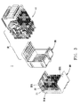
FIG. 3 is a disassembled view of the high speed connector assembly along another direction;
FIG. 4 is a disassembled view of one terminal module of a receptacle connector of the present invention;
FIG. 5 is a perspective view of one receptacle terminal group of the receptacle connector of the present invention;
FIG. 6 is a perspective view of one row of plug terminals of a plug connector of the present invention;
FIG. 7 is a schematic view of one pair of differential signal receptacle terminals and one pair of differential signal plug terminals after mating; and
FIG. 8 is a schematic view of the two pairs of terminals along another direction after mating.
DETAILED DESCRIPTION OF THE PREFERRED EMBODIMENTS
The following description of every embodiment with reference to the accompanying drawings is used to exemplify a specific embodiment, which may be carried out in the present invention. Directional terms mentioned in the present invention, such as “up”, “down”, “front”, “back”, “left”, “right”, “top”, “bottom” etc., are only used with reference to the orientation of the accompanying drawings. Therefore, the used directional terms are intended to illustrate, but not to limit, the present invention.
Please refer to FIGS. 1 to 3, a high speed connector assembly 1 of the present invention includes a receptacle connector 10 and a plug connector 20. The receptacle connector 10 may be a right-angle connector, the mating direction of which is parallel to a horizontal circuit board (not shown), on which the receptacle connector 10 is mounted. The plug connector 20 may be a vertical end connector, the mating direction of which is perpendicular to a vertical circuit board (not shown), on which the plug connector 20 is mounted.
Please refer to FIGS. 2 and 3, the receptacle connector 10 includes at least an insulating cover 30 and multiple terminal modules 40 mounted in the insulating cover 30 and arranged in parallel from left to right.
Referring to FIG. 4, each terminal module 40 includes at least an insulating frame 41 and a receptacle terminal group 42 retained in the insulating frame 41. In the embodiment, the terminal module 40 further includes a grounding plate 43 mounted on one side of the insulating frame 41. In the embodiment, the receptacle terminal group 42 and the insulating frame 41 are combined together by injection molding.
Please refer to FIG. 5, the receptacle terminal group 42 includes multiple pairs of differential signal receptacle terminals 420 and multiple grounding receptacle terminals 421. There are two grounding receptacle terminals 421 respectively arranged on two sides of each pair of differential signal receptacle terminals 420. In the embodiment, all of the differential signal receptacle terminals 420 and the grounding receptacle terminals 421 in one receptacle terminal group 42 are located in a first vertical plane 50. Each pair of differential signal receptacle terminals 420 include two differential signal receptacle terminals 420.
Referring to FIG. 5, each differential signal receptacle terminal 420 has a main body 4201 located in the first vertical plane 50, a first L-shaped contact piece 4202 extending forward from one end of the main body 4201, and a mounting portion 4203 extending downward from the other end of the main body 4201.
Referring to FIG. 5, the first L-shaped contact piece 4202 has a first tilted arm 4204 and a first extending section 4206. The first tilted arm 4204 is located in the first vertical plane 50, extends forward from one end of the main body 4201 and tilts toward one adjacent grounding receptacle terminal 421. The first extending section 4206 is connected to a first side edge 4205 of the first tilted arm 4204 and is formed by bending perpendicularly to the first vertical plane 50.
In the embodiment, the first side edge 4205 refers to the side edge of the first tilted arm 4204 adjacent to the adjacent grounding receptacle terminal 421. The first extending section 4206 is located in the front of the first side edge 4205. The first side edge 4205 forms a first notch 4207, which is near the first extending section 4206 or is located in rear of the first extending section 4206.
Referring to FIG. 5, the first L-shaped contact pieces 4202 of each pair of differential signal receptacle terminals 420 are symmetrical in structure. In detail, the first tilted arm 4204 of one differential signal receptacle terminal 420 tilts toward one lower grounding receptacle terminal 421 adjacent to the one differential signal receptacle terminal 420 in the first vertical plane 50, and the first extending section 4206 is formed on a lower side edge (that is, the first side edge 4205) of the first tilted arm 4204. The first tilted arm 4204′ of the other differential signal receptacle terminal 420 tilts toward one upper grounding receptacle terminal 421 adjacent to the other differential signal receptacle terminal 420 in the first vertical plane 50, and the first extending section 4206′ is formed on an upper side edge (that is, the first side edge 4205′) of the first tilted arm 4204′. Therefore, the two first L-shaped contact pieces 4202, 4202′ of the pair of differential signal receptacle terminals 420 are together configured to be splayed apart.
In the embodiment, the mounting portion 4203 is located in the first vertical plane 50 and is a needle shaped pin, which can be connected to a signal point of the horizontal circuit board.
As shown in FIG. 5, in the embodiment, the grounding receptacle terminal 421 and the differential signal receptacle terminal 420 have roughly the same structure, and the biggest difference is that the dimensions of their main bodies 4201, 4211 are different. For example, the width of the main body 4211 of the grounding receptacle terminal 421 is larger than that of the main body 4201 of the differential signal receptacle terminal 420. Hence, the structure of the grounding receptacle terminal 421 will no longer be described in detail here.
Referring to FIG. 3, the plug connector 20 includes a plug housing 21 and multiple rows of plug terminals 22 mounted in the plug housing 21. The plug housing 21 has a base 210 and two sidewalls 211 standing on two sides of the base 210. These plug terminals 22 are mounted on the base 210 and can be electrically connected to the corresponding terminal modules 40.
Please refer to FIG. 6, each row of plug terminals 22 includes multiple pairs of differential signal plug terminals 220 and multiple grounding plug terminals 221. There are two grounding plug terminals 221 respectively arranged on two sides of each pair of differential signal plug terminals 220. In the embodiment, these differential signal plug terminals 220 and these grounding plug terminals 221, which are arranged in the same row, are located in a second vertical plane 60. Each pair of differential signal plug terminals 220 include two differential signal plug terminals 220. In the embodiment, the grounding plug terminal 221 and the differential signal plug terminal 220 have roughly the same structure.
The following text takes one of the differential signal plug terminals 220 as an example to specifically describe the structure of the plug terminal 22 of the present invention.
Referring to FIG. 6, the differential signal plug terminal 220 has a straight section 2201, a second L-shaped contact piece 2202 extending upward from one end of the straight section 2201, and a mounting end 2203 extending downward from the other end of the straight section 2201. The second L-shaped contact piece 2202 has a second tilted arm 2204 and a second extending section 2206. The second tilted arm 2204 is located in the second vertical plane 60, extends upward from one end of the straight section 2201 and tilts toward one adjacent grounding plug terminal 221. The second extending section 2206 is connected to a second side edge 2205 of the second tilted arm 2204 and is formed by bending perpendicularly to the second vertical plane 60.
In the embodiment, the second side edge 2205 refers to the side edge of the second tilted arm 2204 adjacent to the adjacent grounding plug terminal 221. The second extending section 2206 is located in the front of the second side edge 2205. The second side edge 2205 forms a second notch 2207, which is near the second extending section 2206 or is located in rear of the second extending section 2206.
Referring to FIG. 6, each pair of differential signal plug terminals 220 are symmetrical to each other. In detail, the second extending section 2206 of the second L-shaped contact piece 2202 of one differential signal plug terminal 220 is located on a left side edge (that is, the second side edge 2205) of the second tilted arm 2204, and the second extending section 2206′ of the second L-shaped contact piece 2202′ of the other differential signal plug terminal 220 is located on a right side edge (that is, the second side edge 2205′) of the second tilted arm 2204′. Therefore, the two second L-shaped contact pieces 2202, 2202′ of the pair of differential signal plug terminals 220 are together configured to be splayed apart.
In the embodiment, the second vertical plane 60 is parallel to the first vertical plane 50.
In the embodiment, the mounting end 2203 is located in the second vertical plane 60 and is a needle shaped pin, which can be connected to a signal point of the horizontal circuit board.
The following text will introduce the electrical engagement between the receptacle terminal 420 and the plug terminal 220.
Please refer to FIGS. 7 and 8, when the receptacle connector 10 and the plug connector 20 shown in FIG. 1 are electrically engaged with each other, the second extending sections 2206 of each pair of differential signal plug terminals 220 are inserted between the first extending sections 4206 of the corresponding pair of differential signal receptacle terminals 420. Then, each second extending section 2206 slides along the corresponding first extending section 4206, and the second extending section 2206 enters into the corresponding first notch 4207. Next, the second extending section 2206 leaves the corresponding first notch 4207, slides a predetermined distance toward the corresponding main body 4201 along the first side edge 4205 of the first tilted arm 4204, and finally stops on the first side edge 4205. Meanwhile, the first extending section 4206 passes by the corresponding second notch 2207 and slides the predetermined distance toward the corresponding straight section 2201 along the second side edge 2205 of the second tilted arm 2204, and finally stops on the second side edge 2205.
After the differential signal plug terminal 220 and the differential signal receptacle terminal 420 are mated together, the second extending section 2206 of the differential signal plug terminal 220 is pressed onto the first side edge 4205 of the differential signal receptacle terminal 420, and the first extending section 4206 of the differential signal receptacle terminal 420 is pressed onto the second side edge 2205 of the differential signal plug terminal 220. Therefore there forms double contacts, produces a balanced contact force, and forms a stable electrical connection between the receptacle terminal and the plug terminal mated together.
As described above, the high speed connector assembly 1 of the present invention employs the receptacle terminals 420 and the plug terminals 22, each of which disposes an L-shaped contact piece 4202, 2202. The L-shaped contact piece 4202 of each receptacle terminal 420 can electrically contact with the side edge 2205 of the corresponding plug terminal 22, and the L-shaped contact piece 2202 of each plug terminal 22 also can electrically contact with the side edge 4205 of the corresponding receptacle terminal 420, thereby producing a balanced contact force and further forming a stable electrical connection between the receptacle terminal 420 and the plug terminal 22 when mating together.
It is to be understood, however, that even though numerous characteristics and advantages of the present invention have been set forth in the foregoing description, together with details of the structure and function of the invention, the disclosure is illustrative only, and changes may be made in detail, especially in matters of shape, size, and arrangement of parts within the principles of the invention to the full extent indicated by the broad general meaning of the terms in which the appended claims are expressed.

Claims (10)

What is claimed is:
1. A high speed connector assembly, which comprises:
a receptacle connector including at least an insulating cover and multiple terminal modules mounted in the insulating cover and arranged in parallel; each terminal module including an insulating frame and a receptacle terminal group retained in the insulating frame; the receptacle terminal group being located in a first vertical plane and including multiple pairs of differential signal receptacle terminals and multiple grounding receptacle terminals; two grounding receptacle terminals being respectively arranged on two sides of each pair of differential signal receptacle terminals; each pair of differential signal receptacle terminals including two differential signal receptacle terminals, each of which has a main body located in the first vertical plane, a first L-shaped contact piece extending forward from one end of the main body, and a mounting portion extending downward from the other end of the main body; wherein the first L-shaped contact piece has a first tilted arm and a first extending section; the first tilted arm being located in the first vertical plane, extending upward from one end of the main body and tilting toward the grounding receptacle terminal adjacent to the differential signal receptacle terminal; the first extending section being connected to a first side edge of the first tilted arm and being formed by bending perpendicularly to the first vertical plane; the first L-shaped contact pieces of each pair of differential signal receptacle terminals being symmetrical to each other, and being together configured to be splayed apart; and
a plug connector including a plug housing and multiple rows of plug terminals mounted in the plug housing; each row of plug terminals being located in a second vertical plane and including multiple pairs of differential signal plug terminals and multiple grounding plug terminals; two grounding plug terminals being respectively disposed on two sides of each pair of differential signal plug terminals; each pair of differential signal plug terminals including two differential signal plug terminals, each of which has a straight section located in the second vertical plane, a second L-shaped contact piece extending upward from one end of the straight section, and a mounting end extending downward from the other end of the straight section; wherein the second L-shaped contact piece has a second tilted arm and a second extending section; the second tilted arm being located in the second vertical plane, extending upward from one end of the straight section and tilting toward the grounding plug terminal adjacent to the differential signal plug terminal; the second extending section being connected to a second side edge of the second tilted arm and being formed by bending perpendicularly to the second vertical plane; the second L-shaped contact pieces of each pair of differential signal plug terminals being symmetrical to each other, and being together configured to be splayed apart;
when the receptacle connector and the plug connector are electrically engaged with each other, the second extending section of the differential signal plug terminal being pressed onto the first side edge of the differential signal receptacle terminal, and the first extending section of the differential signal receptacle terminal being pressed onto the second side edge of the differential signal plug terminal, thereby forming a stable electrical connection.
2. The high speed connector assembly as claimed in claim 1, wherein the first extending section is located in the front of the first side edge of the first tilted arm, and the first side edge forms a first notch near the first extending section; and
the second extending section is located in the front of the second side edge of the second tilted arm, and the second side edge forms a second notch near the second extending section.
3. The high speed connector assembly as claimed in claim 1, wherein the second vertical plane is parallel to the first vertical plane.
4. A receptacle connector, which comprises:
at least an insulating cover, and
multiple terminal modules mounted in the insulating cover and arranged in parallel; each terminal module including an insulating frame and a receptacle terminal group retained in the insulating frame; the receptacle terminal group being located in a first vertical plane and including multiple pairs of differential signal receptacle terminals and multiple grounding receptacle terminals; two grounding receptacle terminals being respectively arranged on two sides of each pair of differential signal receptacle terminals; each pair of differential signal receptacle terminals including two differential signal receptacle terminals, each of which has a main body located in the first vertical plane, a first L-shaped contact piece extending forward from one end of the main body, and a mounting portion extending downward from the other end of the main body;
wherein the first L-shaped contact piece has a first tilted arm and a first extending section; the first tilted arm being located in the first vertical plane, extending upward from one end of the main body and tilting toward the grounding receptacle terminal adjacent to the differential signal receptacle terminal; the first extending section being connected to a first side edge of the first tilted arm and being formed by bending perpendicularly to the first vertical plane; the first L-shaped contact pieces of each pair of differential signal receptacle terminals being symmetrical to each other, and being together configured to be splayed apart.
5. The receptacle connector as claimed in claim 4, wherein the first extending section is located in the front of the first side edge of the first tilted arm, and the first side edge forms a first notch near the first extending section.
6. The receptacle connector as claimed in claim 4, wherein the terminal module further includes a grounding plate mounted on one side of the insulating frame, and the mounting portion is located in the first vertical plane.
7. A plug connector, which comprises:
a plug housing; and
multiple rows of plug terminals mounted in the plug housing; each row of plug terminals being located in a second vertical plane and including multiple pairs of differential signal plug terminals and multiple grounding plug terminals; two grounding plug terminals being respectively disposed on two sides of each pair of differential signal plug terminals; each pair of differential signal plug terminals including two differential signal plug terminals, each of which has a straight section located in the second vertical plane, a second L-shaped contact piece extending upward from one end of the straight section, and a mounting end extending downward from the other end of the straight section;
wherein the second L-shaped contact piece has a second tilted arm and a second extending section; the second tilted arm being located in the second vertical plane, extending upward from one end of the straight section and tilting toward the grounding plug terminal adjacent to the differential signal plug terminal; the second extending section being connected to a second side edge of the second tilted arm and being formed by bending perpendicularly to the second vertical plane; the second L-shaped contact pieces of each pair of differential signal plug terminals being symmetrical to each other, and being together configured to be splayed apart.
8. The plug connector as claimed in claim 7, wherein the plug housing has a base and two sidewalls standing on two sides of the base; and these plug terminals are mounted on the base.
9. The plug connector as claimed in claim 7, wherein the second extending section is located in the front of the second side edge of the second tilted arm, and the second side edge forms a second notch near the second extending section.
10. The plug connector as claimed in claim 7, wherein the mounting end is located in the second vertical plane.
US15/453,922 2016-08-03 2017-03-09 High speed connector assembly, receptacle connector and plug connector Active US9893471B1 (en)

Applications Claiming Priority (3)

Application Number Priority Date Filing Date Title
CN201610627021 2016-08-03
CN201610627021.5 2016-08-03
CN201610627021.5A CN106058544B (en) 2016-08-03 2016-08-03 High speed connector component, socket connector and pin connector

Publications (2)

Publication Number Publication Date
US20180040989A1 US20180040989A1 (en) 2018-02-08
US9893471B1 true US9893471B1 (en) 2018-02-13

Family

ID=57196218

Family Applications (1)

Application Number Title Priority Date Filing Date
US15/453,922 Active US9893471B1 (en) 2016-08-03 2017-03-09 High speed connector assembly, receptacle connector and plug connector

Country Status (4)

Country Link
US (1) US9893471B1 (en)
EP (1) EP3280007A1 (en)
CN (1) CN106058544B (en)
TW (1) TWM537321U (en)

Cited By (3)

* Cited by examiner, † Cited by third party
Publication number Priority date Publication date Assignee Title
USD872699S1 (en) * 2018-07-05 2020-01-14 Oupiin Electronic (Kunshan) Co., Ltd. Differential signal terminal with two non-coplanar branches of unequal length
USD875688S1 (en) * 2018-07-05 2020-02-18 Oupiin Electronic (Kunshan) Co., Ltd. Differential signal terminal with an opening
US20200194941A1 (en) * 2018-12-17 2020-06-18 Oupiin Electronic (Kunshan) Co., Ltd. High speed connector assembly, socket connector and grounding plate

Families Citing this family (33)

* Cited by examiner, † Cited by third party
Publication number Priority date Publication date Assignee Title
WO2014031851A1 (en) 2012-08-22 2014-02-27 Amphenol Corporation High-frequency electrical connector
CN107112696B (en) 2014-11-12 2020-06-09 安费诺有限公司 Very high speed, high density electrical interconnect system with impedance control in the mating region
TWI790785B (en) 2016-05-31 2023-01-21 美商安芬諾股份有限公司 Electrical termination, a cable assembly and a method for terminating a cable
WO2018075777A1 (en) 2016-10-19 2018-04-26 Amphenol Corporation Compliant shield for very high speed, high density electrical interconnection
US10355383B2 (en) 2017-03-13 2019-07-16 Te Connectivity Corporation Circuit card assemblies for a communication system
TWI788394B (en) 2017-08-03 2023-01-01 美商安芬諾股份有限公司 Cable assembly and method of manufacturing the same
US10553968B2 (en) 2017-08-09 2020-02-04 Te Connectivity Corporation Electrical connector for a circuit card assembly of a communication system
US10411378B2 (en) 2017-08-09 2019-09-10 Te Connectivity Corporation Circuit card assemblies for a communication system
US11025004B2 (en) 2017-08-09 2021-06-01 TE Connectivity Services Gmbh Circuit card assemblies for a communication system
US10522925B2 (en) 2017-09-29 2019-12-31 Te Connectivity Corporation Circuit card assemblies for a communication system
US10381762B2 (en) 2017-09-29 2019-08-13 Te Connectivity Corporation Electrical connector for a circuit card assembly of a communication system
US10461470B2 (en) 2018-02-14 2019-10-29 Te Connectivity Corporation Circuit card assemblies for a communication system
US10665973B2 (en) 2018-03-22 2020-05-26 Amphenol Corporation High density electrical connector
CN115632285A (en) 2018-04-02 2023-01-20 安达概念股份有限公司 Controlled impedance cable connector and device coupled with same
USD950498S1 (en) 2018-11-05 2022-05-03 Samtec, Inc. Connector
US10931062B2 (en) 2018-11-21 2021-02-23 Amphenol Corporation High-frequency electrical connector
CN109546384B (en) * 2018-12-17 2024-02-23 欧品电子(昆山)有限公司 High-speed connector assembly, socket connector and grounding plate
US10587064B1 (en) 2019-01-23 2020-03-10 Te Connectivity Corporation Circuit card assemblies for a communication system
US11189943B2 (en) 2019-01-25 2021-11-30 Fci Usa Llc I/O connector configured for cable connection to a midboard
US11101611B2 (en) 2019-01-25 2021-08-24 Fci Usa Llc I/O connector configured for cabled connection to the midboard
WO2020172395A1 (en) 2019-02-22 2020-08-27 Amphenol Corporation High performance cable connector assembly
US10741950B1 (en) 2019-03-14 2020-08-11 Te Connectivity Corporation Circuit card assemblies for a communication system
CN109841981B (en) * 2019-03-22 2024-02-23 欧品电子(昆山)有限公司 High-speed backboard connector and bottom cover thereof
TW202114301A (en) 2019-09-19 2021-04-01 美商安芬諾股份有限公司 High speed electronic system with midboard cable connector
US11063391B2 (en) 2019-10-11 2021-07-13 TE Connectivity Services Gmbh Circuit card assemblies for a communication system
US11469554B2 (en) 2020-01-27 2022-10-11 Fci Usa Llc High speed, high density direct mate orthogonal connector
TW202135385A (en) 2020-01-27 2021-09-16 美商Fci美國有限責任公司 High speed connector
CN113258325A (en) 2020-01-28 2021-08-13 富加宜(美国)有限责任公司 High-frequency middle plate connector
CN111478088A (en) * 2020-05-27 2020-07-31 东莞立讯技术有限公司 Terminal structure and connector
CN112652906B (en) 2020-06-19 2022-12-02 东莞立讯技术有限公司 Plugging module and cable connector
CN111682369B (en) 2020-06-19 2021-08-03 东莞立讯技术有限公司 Back panel connector
CN112736524B (en) 2020-12-28 2022-09-09 东莞立讯技术有限公司 Terminal module and backplane connector
USD1002553S1 (en) 2021-11-03 2023-10-24 Amphenol Corporation Gasket for connector

Citations (9)

* Cited by examiner, † Cited by third party
Publication number Priority date Publication date Assignee Title
US6224432B1 (en) * 1999-12-29 2001-05-01 Berg Technology, Inc. Electrical contact with orthogonal contact arms and offset contact areas
US6227882B1 (en) * 1997-10-01 2001-05-08 Berg Technology, Inc. Connector for electrical isolation in a condensed area
US6379188B1 (en) * 1997-02-07 2002-04-30 Teradyne, Inc. Differential signal electrical connectors
US7331830B2 (en) * 2006-03-03 2008-02-19 Fci Americas Technology, Inc. High-density orthogonal connector
US7731537B2 (en) * 2007-06-20 2010-06-08 Molex Incorporated Impedance control in connector mounting areas
US8408939B2 (en) * 2010-11-19 2013-04-02 Tyco Electronics Corporations Electrical connector system
US9787029B1 (en) * 2016-06-13 2017-10-10 Oupiin Electronic (Kunshan) Co., Ltd. High speed connector assembly, receptacle connector and plug connector
US9825392B1 (en) * 2016-06-22 2017-11-21 Oupiin Electronic (Kunshan) Co., Ltd High speed connector assembly, receptacle connector and receptacle terminal
US9843119B1 (en) * 2016-06-08 2017-12-12 Oupiin Electronic (Kunshan) Co., Ltd High speed connector assembly, receptacle connector and receptacle terminal

Family Cites Families (9)

* Cited by examiner, † Cited by third party
Publication number Priority date Publication date Assignee Title
US5215473A (en) * 1992-05-05 1993-06-01 Molex Incorporated High speed guarded cavity backplane connector
CN101335407B (en) * 2007-06-28 2010-11-10 贵州航天电器股份有限公司 High speed transmission electric connector with shielding plate indirect earthed
CN201490476U (en) * 2009-08-28 2010-05-26 莫列斯公司 Connector with overlapped grounding structure
CN102117993B (en) * 2009-12-30 2013-05-08 富士康(昆山)电脑接插件有限公司 Electric connector
US7963806B1 (en) * 2010-03-19 2011-06-21 Hon Hai Precision Ind. Co., Ltd. Electrical connector and assembly with aligned contacting arms
CN202076609U (en) * 2011-03-23 2011-12-14 富士康(昆山)电脑接插件有限公司 Electric connector
US9362646B2 (en) * 2013-03-15 2016-06-07 Amphenol Corporation Mating interfaces for high speed high density electrical connector
CN203631787U (en) * 2013-08-20 2014-06-04 富士康(昆山)电脑接插件有限公司 Electric connector
CN205921124U (en) * 2016-08-03 2017-02-01 欧品电子(昆山)有限公司 High speed connector subassembly, socket connector and plug connector

Patent Citations (9)

* Cited by examiner, † Cited by third party
Publication number Priority date Publication date Assignee Title
US6379188B1 (en) * 1997-02-07 2002-04-30 Teradyne, Inc. Differential signal electrical connectors
US6227882B1 (en) * 1997-10-01 2001-05-08 Berg Technology, Inc. Connector for electrical isolation in a condensed area
US6224432B1 (en) * 1999-12-29 2001-05-01 Berg Technology, Inc. Electrical contact with orthogonal contact arms and offset contact areas
US7331830B2 (en) * 2006-03-03 2008-02-19 Fci Americas Technology, Inc. High-density orthogonal connector
US7731537B2 (en) * 2007-06-20 2010-06-08 Molex Incorporated Impedance control in connector mounting areas
US8408939B2 (en) * 2010-11-19 2013-04-02 Tyco Electronics Corporations Electrical connector system
US9843119B1 (en) * 2016-06-08 2017-12-12 Oupiin Electronic (Kunshan) Co., Ltd High speed connector assembly, receptacle connector and receptacle terminal
US9787029B1 (en) * 2016-06-13 2017-10-10 Oupiin Electronic (Kunshan) Co., Ltd. High speed connector assembly, receptacle connector and plug connector
US9825392B1 (en) * 2016-06-22 2017-11-21 Oupiin Electronic (Kunshan) Co., Ltd High speed connector assembly, receptacle connector and receptacle terminal

Cited By (4)

* Cited by examiner, † Cited by third party
Publication number Priority date Publication date Assignee Title
USD872699S1 (en) * 2018-07-05 2020-01-14 Oupiin Electronic (Kunshan) Co., Ltd. Differential signal terminal with two non-coplanar branches of unequal length
USD875688S1 (en) * 2018-07-05 2020-02-18 Oupiin Electronic (Kunshan) Co., Ltd. Differential signal terminal with an opening
US20200194941A1 (en) * 2018-12-17 2020-06-18 Oupiin Electronic (Kunshan) Co., Ltd. High speed connector assembly, socket connector and grounding plate
US10931063B2 (en) * 2018-12-17 2021-02-23 Oupiin Electronic (Kunshan) Co., Ltd. High speed connector assembly, socket connector and grounding plate

Also Published As

Publication number Publication date
CN106058544A (en) 2016-10-26
US20180040989A1 (en) 2018-02-08
EP3280007A1 (en) 2018-02-07
CN106058544B (en) 2018-11-30
TWM537321U (en) 2017-02-21

Similar Documents

Publication Publication Date Title
US9893471B1 (en) High speed connector assembly, receptacle connector and plug connector
US9843119B1 (en) High speed connector assembly, receptacle connector and receptacle terminal
US9825392B1 (en) High speed connector assembly, receptacle connector and receptacle terminal
US10931063B2 (en) High speed connector assembly, socket connector and grounding plate
US9787029B1 (en) High speed connector assembly, receptacle connector and plug connector
US9281590B1 (en) Electrical connector having improved resonance
US20160006182A1 (en) Electrical Connector with Ground Bus
US9853403B1 (en) Board to board connector assembly, female connector and male connector
US20150162714A1 (en) Electrical connector with improved contacts
JP2013041771A (en) Connection connector
US8398422B2 (en) Card edge connector
CN209029559U (en) High speed connector component, socket connector and its female terminal
US20200014149A1 (en) High-speed connector assembly, socket connector and socket terminal
US9312650B1 (en) Plug connector, receptacle connector and electrical connector assembly
US20190207337A1 (en) Wafer group and signal terminal assembly
US9905948B1 (en) Electrical connector with a better flatness of soldering tails
US7892033B2 (en) Electrical connector ensuring proper connection
US9004934B2 (en) Card edge connector
US20200014150A1 (en) High-speed connector assembly, socket connector and socket terminal
US6419502B1 (en) Electrical connector assembly with improved contact arrangement
US9337589B2 (en) Electrical connector with metal plate
US10446964B2 (en) High density connector and wafer group
US8162678B2 (en) Electrical connector having board eschewing cavity
US7815444B2 (en) Low profile electrical connector
US20110159473A1 (en) Array of electrical connectors having offset electrical connectors

Legal Events

Date Code Title Description
AS Assignment

Owner name: OUPIIN ELECTRONIC (KUNSHAN) CO., LTD, CHRISTMAS IS

Free format text: ASSIGNMENT OF ASSIGNORS INTEREST;ASSIGNOR:CHEN, HSIN CHIH;REEL/FRAME:041512/0096

Effective date: 20170223

AS Assignment

Owner name: OUPIIN ELECTRONIC (KUNSHAN) CO., LTD, CHINA

Free format text: CORRECTIVE ASSIGNMENT TO CORRECT THE ASSIGNEE'S CITY PREVIOUSLY RECORDED AT REEL: 041512 FRAME: 0096. ASSIGNOR(S) HEREBY CONFIRMS THE ASSIGNMENT;ASSIGNOR:CHEN, HSIN CHIH;REEL/FRAME:042103/0670

Effective date: 20170123

STCF Information on status: patent grant

Free format text: PATENTED CASE

MAFP Maintenance fee payment

Free format text: PAYMENT OF MAINTENANCE FEE, 4TH YR, SMALL ENTITY (ORIGINAL EVENT CODE: M2551); ENTITY STATUS OF PATENT OWNER: SMALL ENTITY

Year of fee payment: 4