US9890734B2 - Engine with cylinders each having direct injection nozzle and port injection nozzle, and injecting fuel from port injection nozzle when intake valve is closed during initial fuel injection - Google Patents
Engine with cylinders each having direct injection nozzle and port injection nozzle, and injecting fuel from port injection nozzle when intake valve is closed during initial fuel injection Download PDFInfo
- Publication number
- US9890734B2 US9890734B2 US14/704,307 US201514704307A US9890734B2 US 9890734 B2 US9890734 B2 US 9890734B2 US 201514704307 A US201514704307 A US 201514704307A US 9890734 B2 US9890734 B2 US 9890734B2
- Authority
- US
- United States
- Prior art keywords
- engine
- cylinders
- cylinder
- fuel
- injection
- Prior art date
- Legal status (The legal status is an assumption and is not a legal conclusion. Google has not performed a legal analysis and makes no representation as to the accuracy of the status listed.)
- Expired - Fee Related, expires
Links
Images


Classifications
-
- F—MECHANICAL ENGINEERING; LIGHTING; HEATING; WEAPONS; BLASTING
- F02—COMBUSTION ENGINES; HOT-GAS OR COMBUSTION-PRODUCT ENGINE PLANTS
- F02D—CONTROLLING COMBUSTION ENGINES
- F02D41/00—Electrical control of supply of combustible mixture or its constituents
- F02D41/30—Controlling fuel injection
- F02D41/3094—Controlling fuel injection the fuel injection being effected by at least two different injectors, e.g. one in the intake manifold and one in the cylinder
-
- F—MECHANICAL ENGINEERING; LIGHTING; HEATING; WEAPONS; BLASTING
- F02—COMBUSTION ENGINES; HOT-GAS OR COMBUSTION-PRODUCT ENGINE PLANTS
- F02D—CONTROLLING COMBUSTION ENGINES
- F02D41/00—Electrical control of supply of combustible mixture or its constituents
- F02D41/008—Controlling each cylinder individually
-
- F—MECHANICAL ENGINEERING; LIGHTING; HEATING; WEAPONS; BLASTING
- F02—COMBUSTION ENGINES; HOT-GAS OR COMBUSTION-PRODUCT ENGINE PLANTS
- F02D—CONTROLLING COMBUSTION ENGINES
- F02D41/00—Electrical control of supply of combustible mixture or its constituents
- F02D41/02—Circuit arrangements for generating control signals
- F02D41/04—Introducing corrections for particular operating conditions
- F02D41/047—Taking into account fuel evaporation or wall wetting
-
- F—MECHANICAL ENGINEERING; LIGHTING; HEATING; WEAPONS; BLASTING
- F02—COMBUSTION ENGINES; HOT-GAS OR COMBUSTION-PRODUCT ENGINE PLANTS
- F02D—CONTROLLING COMBUSTION ENGINES
- F02D41/00—Electrical control of supply of combustible mixture or its constituents
- F02D41/02—Circuit arrangements for generating control signals
- F02D41/04—Introducing corrections for particular operating conditions
- F02D41/06—Introducing corrections for particular operating conditions for engine starting or warming up
- F02D41/062—Introducing corrections for particular operating conditions for engine starting or warming up for starting
-
- F—MECHANICAL ENGINEERING; LIGHTING; HEATING; WEAPONS; BLASTING
- F02—COMBUSTION ENGINES; HOT-GAS OR COMBUSTION-PRODUCT ENGINE PLANTS
- F02D—CONTROLLING COMBUSTION ENGINES
- F02D41/00—Electrical control of supply of combustible mixture or its constituents
- F02D41/02—Circuit arrangements for generating control signals
- F02D41/04—Introducing corrections for particular operating conditions
- F02D41/06—Introducing corrections for particular operating conditions for engine starting or warming up
- F02D41/062—Introducing corrections for particular operating conditions for engine starting or warming up for starting
- F02D41/064—Introducing corrections for particular operating conditions for engine starting or warming up for starting at cold start
-
- F—MECHANICAL ENGINEERING; LIGHTING; HEATING; WEAPONS; BLASTING
- F02—COMBUSTION ENGINES; HOT-GAS OR COMBUSTION-PRODUCT ENGINE PLANTS
- F02D—CONTROLLING COMBUSTION ENGINES
- F02D41/00—Electrical control of supply of combustible mixture or its constituents
- F02D41/30—Controlling fuel injection
- F02D41/32—Controlling fuel injection of the low pressure type
- F02D41/34—Controlling fuel injection of the low pressure type with means for controlling injection timing or duration
- F02D41/345—Controlling injection timing
-
- F—MECHANICAL ENGINEERING; LIGHTING; HEATING; WEAPONS; BLASTING
- F02—COMBUSTION ENGINES; HOT-GAS OR COMBUSTION-PRODUCT ENGINE PLANTS
- F02M—SUPPLYING COMBUSTION ENGINES IN GENERAL WITH COMBUSTIBLE MIXTURES OR CONSTITUENTS THEREOF
- F02M69/00—Low-pressure fuel-injection apparatus ; Apparatus with both continuous and intermittent injection; Apparatus injecting different types of fuel
- F02M69/04—Injectors peculiar thereto
- F02M69/042—Positioning of injectors with respect to engine, e.g. in the air intake conduit
- F02M69/046—Positioning of injectors with respect to engine, e.g. in the air intake conduit for injecting into both the combustion chamber and the intake conduit
-
- F—MECHANICAL ENGINEERING; LIGHTING; HEATING; WEAPONS; BLASTING
- F02—COMBUSTION ENGINES; HOT-GAS OR COMBUSTION-PRODUCT ENGINE PLANTS
- F02D—CONTROLLING COMBUSTION ENGINES
- F02D2250/00—Engine control related to specific problems or objectives
- F02D2250/31—Control of the fuel pressure
-
- Y—GENERAL TAGGING OF NEW TECHNOLOGICAL DEVELOPMENTS; GENERAL TAGGING OF CROSS-SECTIONAL TECHNOLOGIES SPANNING OVER SEVERAL SECTIONS OF THE IPC; TECHNICAL SUBJECTS COVERED BY FORMER USPC CROSS-REFERENCE ART COLLECTIONS [XRACs] AND DIGESTS
- Y02—TECHNOLOGIES OR APPLICATIONS FOR MITIGATION OR ADAPTATION AGAINST CLIMATE CHANGE
- Y02T—CLIMATE CHANGE MITIGATION TECHNOLOGIES RELATED TO TRANSPORTATION
- Y02T10/00—Road transport of goods or passengers
- Y02T10/10—Internal combustion engine [ICE] based vehicles
- Y02T10/40—Engine management systems
Definitions
- the present invention relates to an engine which has two systems of fuel injection nozzles, one of which includes fuel injection nozzles for direct injections in cylinders and another of which includes fuel injection nozzles for port injections.
- the engine controls fuel injection by selectively using one of the systems when the engine is started.
- an internal combustion engine provided with a fuel injection valve for cylinder injections and a fuel injection valve for intake port injections. Improvement of fuel efficiency is attempted by selectively using one of the two fuel valves in accordance with the driving state. Since the engine temperature is low, what is called “cold state”, when the internal combustion engine is started, a combustion state is not stabilized in order that evaporation of fuel does not proceed. It is expected that the vaporization of fuel is facilitated by making the pressure of fuel injected from the fuel injection valve for the cylinder injection in the cylinder high, but there is no residual pressure in many cases when the internal combustion engine is cold state, and it takes a while to sufficiently increase the injection pressure.
- An internal combustion engine described in Patent Document 1 includes a main injector for injecting and supplying fuel directly into a cylinder, and a sub-injector for injecting and supplying fuel into an intake passage.
- a fuel injection control unit of this internal combustion engine injects fuel in an intake stroke from at least the sub-injector when the fuel injection pressure measured by a pressure sensor is lower than a predetermined pressure and when temperature of engine cooling water measured by a temperature sensor is lower than predetermined temperature. It is described that even if the pressure of injected fuel is low and the diameter of fuel particles is large, the fuel is vaporized before it is supplied to the cylinder, and is mixed with air.
- An internal combustion engine described in Patent Document 2 includes an intra-cylinder injector for injecting fuel into a cylinder and an intake passage injector for injecting fuel into an intake passage.
- a control unit of the internal combustion engine injects fuel only from the intra-cylinder injector when the internal combustion engine is warm, and the control unit injects fuel only from the intake passage injector when the internal combustion engine is cold.
- Fuel is injected by the intra-cylinder injector during a compression stroke, and fuel is injected by the intake passage injector during an intake stroke. It is described that even if the internal combustion engine is cold, vaporization of fuel is facilitated by injecting fuel into the intake passage as in Patent Document 1.
- An internal combustion engine described in Patent Document 3 includes a port injection valve arranged in an intake passage of each of cylinders, and intra-cylinder injection valves arranged in at least two of the cylinders.
- the intra-cylinder injection valve is arranged in each of the cylinders which are arranged such that a stroke is brought into a compression stroke or a power stroke when an arbitrary one cylinder and this cylinder are brought into a stroke other than the compression stroke or other than the power stroke.
- a control unit of the engine injects fuel into cylinders which are in the intake stroke and the exhaust stroke by the port injection valve, and injects fuel into cylinders which are in the compression stroke or the power stroke by the intra-cylinder injection valve.
- Patent Document 1 Jpn. Pat. Appln. KOKAI Publication No. 10-176574
- Patent Document 2 Jpn. Pat. Appln. KOKAI Publication No. 2006-258017
- Patent Document 3 Jpn. Pat. Appln. KOKAI Publication No. 2012-67639
- Patent Documents 1 and 2 when the engine is started from a cold state in which the engine is cold, fuel is injected from the intake passage injector (sub-injector). However, when the engine is started from the cold state, fuel injected from the intake passage injector adheres to an inner surface of an intake port, and the fuel is diluted more than a supplied amount. Hence, in order to obtain injected fuel of originally necessary concentration, it is necessary to inject more fuel. Generally, when an engine which injects fuel through a port is started from the cold state, to secure time during which fuel is sufficiently vaporized, fuel is initially injected into all of the cylinders asynchronously, and is then injected into each of the cylinders in order. When the engine is started from the cold state by the port injection in this manner, more fuel than necessary for combustion is consumed.
- Patent Document 3 is intended for restart after an idling stop, i.e., start in a warm state in which the engine becomes warm, and fuel for start is supplied from the intra-cylinder injection valve.
- an idling stop i.e., start in a warm state in which the engine becomes warm
- fuel for start is supplied from the intra-cylinder injection valve.
- the present invention provides an engine having cylinders each provided with a nozzle through which fuel is injected into an intake port and a nozzle through which fuel is injected into the cylinder, the engine being capable of reducing fuel consumption when started.
- An engine of an embodiment of the present invention includes first nozzles, second nozzles and a control unit.
- the first nozzles are arranged in a plurality of cylinders, respectively, and inject fuel directly to the cylinders.
- the second nozzles are arranged in intake ports of the cylinders, respectively, and inject fuel into the intake ports.
- the control unit controls fuel injection of the first nozzles and the second nozzles. When the engine is started, the control unit performs initial fuel injection by one of the first and second nozzles into the odd-numbered cylinders in terms of first ignition permutation of the cylinders, and performs initial fuel injection by the other one of the first and second nozzles into the even-numbered cylinders.
- control unit performs initial injection by the first nozzles into the even-numbered cylinders in terms of a first ignition permutation. After initial combustion in all of the cylinders is complete, the control unit performs injection by the first nozzles into all of the cylinders until a given operating condition is achieved. After the given operating condition is achieved, the control unit performs injection by the second nozzles into all of the cylinders.
- the given operating condition includes at least one of a condition that the temperature of the engine's cooling water is greater than or equal to a given temperature and a condition that the engine's rate of rotation is greater than or equal to a target rate.
- the second nozzles when the first nozzles initially inject fuel into the odd-numbered cylinders in terms of the first ignition order, the second nozzles initially inject fuel into the even-numbered cylinders in terms of the first ignition order, and when the first nozzle initially inject fuel into the even-numbered cylinders in terms of first ignition order, the second nozzles initially inject fuel into the odd-numbered cylinders in terms of the first ignition order.
- fuel is not continuously injected from the first nozzles, pressure of fuel injected from the first nozzles reaches sufficiently high pressure.
- the control unit performs initial injection by the first nozzles into the even-numbered cylinders in terms of the first ignition order, since it is possible to secure sufficient time for achieving the pressure necessary to inject fuel from the first nozzles, fuel injected from the first nozzles is atomized appropriately in the cylinders, and the engine can be started.
- the control unit performs injection by the first nozzles into all of the cylinders.
- second and subsequent fuel injections are performed through the first nozzles. Therefore, it is possible to improve combustion stability immediately after the engine is started. Since the engine's rate of rotation reaches the target rate at an early stage, the fuel required for starting the engine is reduced.
- fuel is injected from the first nozzle, since the fuel is injected during the compression stroke, it is easily atomized and combustion is improved. Since fuel is injected from the first nozzle directly into the cylinder, it is possible to suppress unnecessary fuel consumption.
- port injection by the second nozzles easily stabilizes the engine output in comparison with intra-cylinder injection by the first nozzles. This is effective for output control of the engine especially during idling, which requires control of an extremely small pulse width.
- the given operating condition includes at least one of the condition that the temperature of the engine's cooling water is greater than or equal to a given temperature and the condition that the engine's rate of rotation is greater than or equal to a target rate
- fuel injected into the intake port through the second nozzle is easily atomized.
- the amount of smoke (hydrocarbon [HC]) caused by fuel injected into the cylinder through the first nozzle is reliably reduced.
- FIG. 1 is a schematic diagram showing an engine of a first embodiment of the present invention.
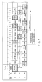
- FIG. 2 is a timing chart of strokes of cylinders, fuel injection and ignition timing when the engine shown in FIG. 1 is started.
- FIG. 3 is a timing chart of the strokes of the cylinders, fuel injection and ignition timing when the engine shown in FIG. 1 is started.
- FIG. 4 is a flowchart when the engine shown in FIG. 1 is started.
- FIG. 5 is a schematic diagram showing an engine of a second embodiment of the present invention.
- FIG. 6 is a timing chart of strokes of cylinders, fuel injection and ignition timing when the engine shown in FIG. 5 is started.
- FIG. 7 is a timing chart of the strokes of the cylinders, fuel injection and ignition timing when the engine shown in FIG. 5 is started.
- the engine 1 is employed as an engine mounted in a vehicle, especially as an engine mounted in a vehicle in which idling stop operation is possible or in a hybrid vehicle.
- the engine 1 shown in FIG. 1 is an in-line four-cylinder engine, and this engine will be described below.
- the engine 1 includes four cylinders # 1 to # 4 , first nozzles Di 1 to Di 4 for injecting fuel directly to intra-cylinders A 1 to A 4 of cylinders # 1 to # 4 , second nozzles Pi 1 to Pi 4 for injecting fuel into intake ports B 1 to B 4 of cylinders # 1 to # 4 , and a control unit 2 for controlling fuel injection in cylinders # 1 to # 4 .
- first nozzles Di 1 to Di 4 for injecting fuel directly to intra-cylinders A 1 to A 4 of cylinders # 1 to # 4
- second nozzles Pi 1 to Pi 4 for injecting fuel into intake ports B 1 to B 4 of cylinders # 1 to # 4
- a control unit 2 for controlling fuel injection in cylinders # 1 to # 4 .
- the control unit (electronic control unit [ECU]) 2 which controls the fuel injection is connected to a sensor 21 for detecting that the vehicle has stopped, an idle switch (ID-SW) 22 for detecting that idling stop control is performed, a temperature sensor 23 for measuring temperature of cooling water of the engine 1 , and an angle sensor 24 for detecting a position of the crank angle.
- a sensor 21 for detecting that the vehicle has stopped it is possible to employ, singularly or in combination, a parking brake, a foot brake, a vehicle speed sensor, a sensor for detecting whether the transmission is in neutral, and an accelerator pedal position sensor.
- the engine 1 of the first embodiment is the in-line four-cylinder four-stroke engine having an intake stroke, a compression stroke, a power stroke and an exhaust stroke. Strokes and ignition order of the cylinders are determined such that cylinders are ignited at the end of the compression stroke in the order of # 1 ⁇ # 3 ⁇ # 4 ⁇ # 2 while taking vibration and torque balance into consideration.
- asterisks shown between the compression stroke and the power stroke mean that ignition is conducted at this timing.
- the control unit 2 When the engine 1 is started, in the first ignition order of cylinders # 1 to # 4 , the control unit 2 performs initial injection into the odd-numbered cylinders by one of the first and second nozzles, and carries out initial injection into the even-numbered cylinders by the other one of the first and second nozzles.
- the initial injection into odd-numbered cylinders # 1 and # 4 is by second nozzles Pi 1 and Pi 4
- the initial injection into even-numbered cylinders # 3 and # 2 is by first nozzles Di 3 and Di 2 , as shown in FIGS. 2 and 3 .
- the present embodiment is configured such that initial injection into cylinders # 1 to # 4 during the starting operation is proceeded by the second nozzles into cylinders which are situated in the exhaust and compression strokes at the beginning of the starting operation, and is proceeded by the first nozzles in the respective compression stroke into cylinders which are situated in the power and intake strokes at the beginning of the starting operation.
- injection is performed by second nozzles Pi 1 and Pi 4 into cylinder # 1 situated in the exhaust stroke and cylinder # 4 situated in the compression stroke when the starting operation of the engine is begun, and injection is performed by first nozzles Di 3 and Di 2 in the respective compression stroke into cylinder # 3 situated in the power stroke and into cylinder # 2 situated in the intake stroke when the starting operation of the engine is begun.
- injections by second nozzles Pi 1 and Pi 4 into cylinder # 1 which is situated in the exhaust stroke and cylinder # 4 which is situated in the compression stroke when the starting operation is begun are performed at the same time at the beginning of the starting operation.
- This fuel injection is asynchronous injection which does not correspond to the crank angle of the engine 1 .
- the control unit 2 when the initial combustion in all of cylinders # 1 to # 4 is complete, the control unit 2 performs injection by nozzles Di 1 to Di 4 into all of cylinders # 1 to # 4 until a given operating condition is achieved.
- the control unit 2 performs injection by second nozzles Pi 1 to Pi 4 into all of cylinders # 1 to # 4 .
- the given operating condition includes at least one of a condition that the temperature of the cooling water of the engine 1 is greater than or equal to a given temperature and a condition that the rate of rotation of the engine 1 is greater than or equal to a target rate.
- the control unit 2 determines (S 1 ) whether the vehicle is stopped based on a signal from the sensor 21 as shown in FIG. 4 . If the vehicle is stopped, it is determined (S 2 ) whether the idle switch 22 is turned ON. If the idle switch 22 is turned ON, i.e., when the engine 1 is stopped, it is determined (S 3 ) whether the temperature measured by the temperature sensor 23 is less than or equal to a predetermined value. In this case, the predetermined value which is set in the temperature sensor 23 is about 20° C. for example.
- cranking is performed (S 5 ) when the engine is during the starting operation, and it is identified (S 6 ) which strokes cylinders # 1 to # 4 are in based on the crank angle detected by the angle sensor 24 .
- asynchronous injection which involves Pi injection is performed for cylinders in the exhaust stroke and the compression stroke at the same time when the control for starting the engine is begun.
- second nozzles Pi 1 and Pi 4 simultaneously inject fuel into intake ports B 1 and B 4 for cylinder # 1 which is in the exhaust stroke and cylinder # 4 which is in the compression stroke when the starting operation begins.
- An intake valve is closed in the compression stroke, the power stroke and the exhaust stroke. Therefore, injected fuel is vaporized in intake ports B 1 and B 4 .
- ignition orders of cylinders # 1 and # 4 in which Pi injection is carried out are first and third.
- fuel is injected (S 8 ) directly into intra-cylinders A 3 and A 2 of cylinders other than asynchronously injected cylinders, i.e., cylinders # 3 and # 2 by first nozzles Di 3 and Di 2 in accordance with the ignition orders.
- Di injection is performed in the initial compression stroke, i.e., in the compression stroke of the third cycle after the starting operation is begun.
- Di injection is performed in the secondary compression stroke, i.e., in the compression stroke of the fifth cycle after the starting operation is begun.
- ignition starts from the end of the second cycle of cylinder # 1 in accordance with the ignition order.
- the cylinders (# 1 , # 4 ) in which Pi injection is preformed and the cylinders (# 3 , # 2 ) in which Di injection is performed are alternately ignited.
- the operation in which cylinders performed Pi injection and cylinders performed Di injection are alternately ignited is kept until at least one ignition sequence of all of cylinders # 1 to # 4 has been ignited.
- the control unit 2 switches fuel injection for all of cylinders # 1 to # 4 to Di injection as shown in FIG. 3 until the given operating condition is satisfied.
- fuel injection for all of cylinders # 1 to # 4 is switched to Pi injection as shown in FIG. 2 .
- temperature of cooling water of the engine 1 and the engine's rate of rotation are monitored as operating conditions.
- the control unit 2 first determines (S 9 ) whether the temperature of the cooling water of the engine 1 is greater than or equal to a given temperature based on the temperature detected by the temperature sensor 23 . If the temperature of the cooling water is greater than or equal to the given temperature, Pi injection control (Pi sequential injection) (S 10 ) is sequentially started from the cylinders which have not yet passed through the exhaust stroke and for which fuel has not yet been injected into the intake ports (B 1 to B 4 ) by the second nozzles (Pi 1 to Pi 4 ), and the mode is shifted to idle (S 11 ).
- Pi injection control Pi sequential injection
- the control unit 2 determines (S 12 ) whether the engine's rate of rotation has become higher than the target rate. If the engine's rate of rotation has become higher than the target rate, Pi injection control (Pi sequential injection) (S 10 ) is sequentially started from the cylinders which have not yet passed through the exhaust stroke and in which fuel has not yet injected into the intake ports (B 1 to B 4 ) by the second nozzles (Pi 1 to Pi 4 ), and the mode is shifted to idle (S 11 ).
- Pi injection control Pi sequential injection
- FIG. 2 shows a case where in control for starting the engine 1 , the given operating condition (when the temperature of the cooling water is greater than or equal to a given temperature or when the engine's rate of rotation has reached a target rate) is satisfied in the third cycle before one ignition sequence of all of the cylinders has been performed. If the given operating condition is satisfied while one ignition sequence is being performed, the control unit 2 switches cylinders # 3 and # 2 in which Di injection is performed until then to Pi injection. In order to ignite for Pi injection at the end of the sixth cycle which is a second cycle for cylinder # 1 , Pi injection is performed in the exhaust stroke of the fourth cycle.
- the given operating condition when the temperature of the cooling water is greater than or equal to a given temperature or when the engine's rate of rotation has reached a target rate
- injection Since fuel injection has not yet been performed in cylinder # 2 at the time of the third cycle, injection is switched to Pi injection after Di injection and ignition is performed in the compression stroke of the fifth cycle. In cylinder # 2 , injection is switched to Pi injection in the exhaust stroke of the seventh cycle.
- FIG. 3 shows a case where in the control for starting the engine 1 , the given operating condition is not satisfied even after one ignition sequence of all of cylinders # 1 to # 4 has been performed, i.e., the temperature of the cooling water is not greater than or equal to the given temperature and the engine's rate of rotation has not reached the target rate. If the given operating condition is not satisfied while one ignition sequence is being performed, the control unit 2 cancels the Pi injection in the exhaust stroke, and thereafter performs Di injection in the compression stroke. That is, in FIG.
- Di injection is performed until the compression stroke immediately thereafter in the cylinders which pass through the exhaust stroke at that time as shown in a tenth cycle of cylinder # 1 and an eleventh cycle of cylinder # 3 .
- Pi injection is started from the exhaust stroke of the tenth cycle and the eleventh cycle in cylinders # 4 and # 2 which have not yet passed through the exhaust stroke.
- asynchronous injection is performed by Pi injection (port injection) for the first and third cylinders (# 1 , # 4 ) in terms of the ignition order at the same time when the starting operation is begun, and Di injection (direct injection) is performed in the compression stroke for the other cylinders (# 3 , # 2 ).
- Pi injection port injection
- Di injection direct injection
- the Di injection is included, even when the engine is started from the cold state, consumed starting fuel is reduced, and exhaust gas component is enhanced, i.e., HC (hydrocarbon) is reduced.
- the Pi injection is performed when the starting operation is begun as the asynchronous injection and thereafter, Di injection is performed in the compression stroke. Hence, the crankshaft rotates at least once until Di injection is performed.
- fuel pressure which is necessary for the Di injection fuel injected by the first nozzle Di is reliably atomized.
- FIGS. 2 and 3 show as if ignition is started from cylinder # 1 , the ignition order does not always start from cylinder # 1 . Ignition may be started from any of cylinders # 1 , # 2 , # 3 , and # 4 in accordance with the crank angle in a state where the engine 1 has stopped. However, when cylinders # 1 , # 2 , # 3 , and # 4 are arranged in series, even if ignition starts from any of cylinders # 1 ⁇ # 3 ⁇ # 4 ⁇ # 2 ⁇ # 1 , a cylinder which is ignited next is determined.
- the engine 1 of the present invention is applied not only to the case where the engine 1 is started from the cold state in a vehicle provided with only the four-cylinder engine 1 , but also be applied to a case where the engine 1 is started from the cold state in a hybrid vehicle including a drive motor and a battery together with the engine 1 .
- FIGS. 5 to 7 An engine 1 of a second embodiment of the present invention will be described with reference to FIGS. 5 to 7 .
- This engine 1 is different from the engine 1 of the first embodiment in that the engine 1 is a three-cylinder engine.
- the same reference symbols or characters are allocated to configurations having the same functions as those of the engine 1 of the first embodiment, and for detailed description thereof, see corresponding description of the first embodiment.
- the engine 1 of the first embodiment is a three-cylinder four-stroke engine as shown in FIG. 5 , and strokes and ignition orders of the cylinders are determined such that the cylinders are ignited at the end of the compression strokes from cylinder # 1 in the order of # 1 ⁇ # 2 ⁇ # 3 ⁇ # 1 as shown in FIGS. 6 and 7 .
- asterisks shown between the compression stroke and the power stroke show ignition timing of cylinders # 1 to # 3 as shown in FIGS. 6 and 7 .
- the engine 1 includes first nozzles Di 1 to Di 3 which are respectively arranged in cylinders # 1 to # 3 and which inject fuel directly to intra-cylinders A 1 to A 3 , second nozzles Pi 1 to Pi 3 which are respectively arranged in intake ports B 1 to B 3 of cylinders # 1 to # 3 and which inject fuel into the intake ports, and a control unit 2 for controlling these members.
- the control unit 2 makes second nozzles (e.g., second nozzles Pi 1 and Pi 3 ) initially inject fuel into the odd-numbered cylinders (e.g., the first cylinder # 1 and the third cylinder # 3 in FIGS. 6 and 7 ) in terms of the initial ignition order of cylinders # 1 to # 3 when the engine 1 is started, and makes first nozzle (e.g., first nozzle Di 2 ) initially inject fuel into the even-numbered cylinder (e.g., the second cylinder # 2 in FIGS. 6 and 7 ).
- first nozzle e.g., first nozzle Di 2
- cylinder # 1 is located in the exhaust stroke
- cylinder # 2 is located in the power stroke
- cylinder # 3 is located in the compression stroke. Since the engine 1 has the three cylinders, there is a phase difference of about 60° between start timings of the respective strokes in a precise sense.
- the control unit 2 makes second nozzles Pi 1 and Pi 3 substantially simultaneously inject fuel into intake ports B 1 and B 3 for the cylinder # 1 which is ignited first and the cylinder # 3 which is ignited third when each cylinder is initially ignited.
- This ignition timing is asynchronous ignition which does not correspond to the crank angle of the engine 1 .
- the first nozzle Di 2 injects fuel directly to the intra-cylinder A 2 and therefore, fuel is injected in the compression stroke of the cylinder # 2 .
- cylinder # 1 is always in the exhaust stroke when the starting control of the engine 1 is begun. If a stroke of the cylinder having the first ignition order is before the compression stroke and after the power stroke, there is secured sufficient time during which fuel injected by second nozzles Pi 1 to Pi 3 into intake ports B 1 to B 3 is vaporized until the fuel is drawn by and loaded into intra-cylinders A 1 to A 3 . As a result, a time until one of first nozzles Di 1 to Di 3 injects fuel into respective intra-cylinders A 1 to A 3 of cylinders # 1 to # 3 having the second ignition order, i.e., until the compression stroke of the cylinder which is ignited second in ignition order, is obtained greater than that until the first cylinder is loaded. That is, there is obtained time during which injection pressure necessary for first nozzles Di 1 to Di 3 is secured.
- the control unit 2 of the engine 1 switches the fuel injection for all of cylinders # 1 to # 3 into the Di-injection by the first nozzles Di 1 to Di 3 when the given operating condition is not satisfied after initial combustion in all of cylinders # 1 to # 3 is completed, and the control unit 2 switches the fuel injection for all of cylinders # 1 to # 3 into the Pi-injection by the second nozzles Pi 1 to Pi 3 when the given operating condition is satisfied after initial combustion in all of cylinders # 1 to # 3 is completed.
- FIG. 6 shows a case where the given operating condition is satisfied when the initial combustion in all of cylinders # 1 to # 3 is completed
- FIG. 7 shows a case where the given operating condition is not satisfied when the initial combustion in all of cylinders # 1 to # 3 is completed. In FIG. 7 , all of second fuel injections for cylinders # 1 to # 3 are performed by Di injection.
- the second embodiment as same as the first embodiment, it is monitored that the temperature of the cooling water of the engine 1 is greater than or equal to the given temperature or that the rate of rotation of the engine 1 is greater than or equal to the target rate, and fuel injections of all of cylinders # 1 to # 3 are switched to the Pi injection performed by second nozzles Pi 1 to Pi 3 when the conditions are satisfied. Since the fuel injection of the Pi injection must be performed earlier than ignition timing as compared with the fuel injection of the Di injection, the Di injection and the Pi injection are mixed in the some sequence as shown in FIG. 7 when Di injection is switched to the Pi injection. In FIG. 7 , it is detected that the engine's rate of rotation exceeds the target rate, and the fuel injection is shifted to the Pi injection.
- the control for starting the engine 1 by the control unit 2 in the second embodiment is the same as that of the first embodiment. Therefore, the control is performed in accordance with the flowchart shown in FIG. 4 .
- S 3 in FIG. 4 it is determined whether the engine 1 is cold state.
- the initial fuel injection into a cylinder having the odd-numbered ignition order is performed by the second nozzles Pi 1 to Pi 3
- the initial fuel injection into a cylinder having the even-numbered ignition order is performed by the first nozzles Di 1 to Di 3 .
Landscapes
- Engineering & Computer Science (AREA)
- Chemical & Material Sciences (AREA)
- Combustion & Propulsion (AREA)
- Mechanical Engineering (AREA)
- General Engineering & Computer Science (AREA)
- Electrical Control Of Air Or Fuel Supplied To Internal-Combustion Engine (AREA)
- Combined Controls Of Internal Combustion Engines (AREA)
- Fuel-Injection Apparatus (AREA)
- Output Control And Ontrol Of Special Type Engine (AREA)
Abstract
Description
Claims (8)
Applications Claiming Priority (3)
| Application Number | Priority Date | Filing Date | Title |
|---|---|---|---|
| JP2012286109A JP5776681B2 (en) | 2012-12-27 | 2012-12-27 | engine |
| JP2012-286109 | 2012-12-27 | ||
| PCT/JP2013/075487 WO2014103447A1 (en) | 2012-12-27 | 2013-09-20 | Engine |
Related Parent Applications (1)
| Application Number | Title | Priority Date | Filing Date |
|---|---|---|---|
| PCT/JP2013/075487 Continuation WO2014103447A1 (en) | 2012-12-27 | 2013-09-20 | Engine |
Publications (2)
| Publication Number | Publication Date |
|---|---|
| US20150233317A1 US20150233317A1 (en) | 2015-08-20 |
| US9890734B2 true US9890734B2 (en) | 2018-02-13 |
Family
ID=51020550
Family Applications (1)
| Application Number | Title | Priority Date | Filing Date |
|---|---|---|---|
| US14/704,307 Expired - Fee Related US9890734B2 (en) | 2012-12-27 | 2015-05-05 | Engine with cylinders each having direct injection nozzle and port injection nozzle, and injecting fuel from port injection nozzle when intake valve is closed during initial fuel injection |
Country Status (5)
| Country | Link |
|---|---|
| US (1) | US9890734B2 (en) |
| EP (1) | EP2940277B1 (en) |
| JP (1) | JP5776681B2 (en) |
| CN (1) | CN104797800B (en) |
| WO (1) | WO2014103447A1 (en) |
Cited By (1)
| Publication number | Priority date | Publication date | Assignee | Title |
|---|---|---|---|---|
| US20180230928A1 (en) * | 2017-02-14 | 2018-08-16 | Toyota Jidosha Kabushiki Kaisha | Fuel injection control device |
Families Citing this family (3)
| Publication number | Priority date | Publication date | Assignee | Title |
|---|---|---|---|---|
| JP6197289B2 (en) * | 2012-12-27 | 2017-09-20 | 三菱自動車工業株式会社 | engine |
| US10094320B2 (en) * | 2015-06-23 | 2018-10-09 | Ford Global Technologies, Llc | Methods and systems for dual fuel injection |
| KR101978071B1 (en) * | 2017-12-04 | 2019-05-13 | 현대오트론 주식회사 | Engine system for controlling dual injectors and intake valves |
Citations (16)
| Publication number | Priority date | Publication date | Assignee | Title |
|---|---|---|---|---|
| US4080949A (en) * | 1974-08-21 | 1978-03-28 | Holec N.V. | Combustion engine and injector for a combustion engine |
| JPH07224699A (en) | 1994-02-10 | 1995-08-22 | Toyota Motor Corp | Internal combustion engine |
| JPH10176574A (en) | 1996-12-19 | 1998-06-30 | Toyota Motor Corp | Fuel injection control device for internal combustion engine |
| US20050016500A1 (en) | 2003-07-22 | 2005-01-27 | Hitachi, Ltd. | Cold start fuel control system |
| JP2005113693A (en) | 2003-10-02 | 2005-04-28 | Toyota Motor Corp | Fuel injection control device for internal combustion engine |
| JP2005226529A (en) | 2004-02-12 | 2005-08-25 | Toyota Motor Corp | Engine fuel injection control device |
| US20050235959A1 (en) | 2004-04-23 | 2005-10-27 | Toyota Jidosha Kabushiki Kaisha | Apparatus and method for controlling fuel injection in internal combustion engine |
| US20060054137A1 (en) | 2004-09-14 | 2006-03-16 | Toyota Jidosha Kabushiki Kaisha | Control apparatus for internal combustion engine |
| US20060207556A1 (en) * | 2005-03-18 | 2006-09-21 | Toyota Jidosha Kabushiki Kaisha | Control apparatus for internal combustion engine |
| US20060207567A1 (en) * | 2005-03-18 | 2006-09-21 | Toyota Jidosha Kabushiki Kaisha | Control apparatus for vehicle |
| US20060225695A1 (en) | 2005-04-08 | 2006-10-12 | Denso Corporation | Startup controller for in-cylinder injection internal combustion engine |
| US20090082937A1 (en) | 2005-03-29 | 2009-03-26 | Toyota Jidosha Kabushiki Kaisha | Fuel injection control device for engine |
| JP2012067639A (en) | 2010-09-22 | 2012-04-05 | Hitachi Automotive Systems Ltd | Internal combustion engine and its control device |
| US20140251280A1 (en) * | 2011-11-25 | 2014-09-11 | Toyota Jidosha Kabushiki Kaisha | Control apparatus for internal combustion engine and control method for internal combustion engine |
| US9222453B2 (en) * | 2012-02-06 | 2015-12-29 | Ford Global Technologies, Llc | Method for restarting an engine |
| US9303577B2 (en) * | 2012-12-19 | 2016-04-05 | Ford Global Technologies, Llc | Method and system for engine cold start and hot start control |
-
2012
- 2012-12-27 JP JP2012286109A patent/JP5776681B2/en active Active
-
2013
- 2013-09-20 EP EP13867556.6A patent/EP2940277B1/en active Active
- 2013-09-20 WO PCT/JP2013/075487 patent/WO2014103447A1/en not_active Ceased
- 2013-09-20 CN CN201380059911.5A patent/CN104797800B/en active Active
-
2015
- 2015-05-05 US US14/704,307 patent/US9890734B2/en not_active Expired - Fee Related
Patent Citations (21)
| Publication number | Priority date | Publication date | Assignee | Title |
|---|---|---|---|---|
| US4080949A (en) * | 1974-08-21 | 1978-03-28 | Holec N.V. | Combustion engine and injector for a combustion engine |
| JPH07224699A (en) | 1994-02-10 | 1995-08-22 | Toyota Motor Corp | Internal combustion engine |
| JPH10176574A (en) | 1996-12-19 | 1998-06-30 | Toyota Motor Corp | Fuel injection control device for internal combustion engine |
| US5924405A (en) | 1996-12-19 | 1999-07-20 | Toyota Jidosha Kabushiki Kaisha | Apparatus and method for injecting fuel in cylinder injection type engines |
| US20050016500A1 (en) | 2003-07-22 | 2005-01-27 | Hitachi, Ltd. | Cold start fuel control system |
| JP2005113693A (en) | 2003-10-02 | 2005-04-28 | Toyota Motor Corp | Fuel injection control device for internal combustion engine |
| JP2005226529A (en) | 2004-02-12 | 2005-08-25 | Toyota Motor Corp | Engine fuel injection control device |
| US7082926B2 (en) * | 2004-04-23 | 2006-08-01 | Toyota Jidosha Kabushiki Kaisha | Apparatus and method for controlling fuel injection in internal combustion engine |
| US20050235959A1 (en) | 2004-04-23 | 2005-10-27 | Toyota Jidosha Kabushiki Kaisha | Apparatus and method for controlling fuel injection in internal combustion engine |
| JP2005307916A (en) | 2004-04-23 | 2005-11-04 | Toyota Motor Corp | Fuel injection control device for internal combustion engine |
| US20060054137A1 (en) | 2004-09-14 | 2006-03-16 | Toyota Jidosha Kabushiki Kaisha | Control apparatus for internal combustion engine |
| US20060207556A1 (en) * | 2005-03-18 | 2006-09-21 | Toyota Jidosha Kabushiki Kaisha | Control apparatus for internal combustion engine |
| US20060207567A1 (en) * | 2005-03-18 | 2006-09-21 | Toyota Jidosha Kabushiki Kaisha | Control apparatus for vehicle |
| JP2006258017A (en) | 2005-03-18 | 2006-09-28 | Toyota Motor Corp | Control device for internal combustion engine |
| CN101091050A (en) | 2005-03-18 | 2007-12-19 | 丰田自动车株式会社 | Controls for vehicles |
| US20090082937A1 (en) | 2005-03-29 | 2009-03-26 | Toyota Jidosha Kabushiki Kaisha | Fuel injection control device for engine |
| US20060225695A1 (en) | 2005-04-08 | 2006-10-12 | Denso Corporation | Startup controller for in-cylinder injection internal combustion engine |
| JP2012067639A (en) | 2010-09-22 | 2012-04-05 | Hitachi Automotive Systems Ltd | Internal combustion engine and its control device |
| US20140251280A1 (en) * | 2011-11-25 | 2014-09-11 | Toyota Jidosha Kabushiki Kaisha | Control apparatus for internal combustion engine and control method for internal combustion engine |
| US9222453B2 (en) * | 2012-02-06 | 2015-12-29 | Ford Global Technologies, Llc | Method for restarting an engine |
| US9303577B2 (en) * | 2012-12-19 | 2016-04-05 | Ford Global Technologies, Llc | Method and system for engine cold start and hot start control |
Cited By (2)
| Publication number | Priority date | Publication date | Assignee | Title |
|---|---|---|---|---|
| US20180230928A1 (en) * | 2017-02-14 | 2018-08-16 | Toyota Jidosha Kabushiki Kaisha | Fuel injection control device |
| US10107225B2 (en) * | 2017-02-14 | 2018-10-23 | Toyota Jidosha Kabushiki Kaisha | Fuel injection control device |
Also Published As
| Publication number | Publication date |
|---|---|
| CN104797800A (en) | 2015-07-22 |
| CN104797800B (en) | 2018-04-24 |
| US20150233317A1 (en) | 2015-08-20 |
| EP2940277B1 (en) | 2018-05-02 |
| JP5776681B2 (en) | 2015-09-09 |
| WO2014103447A1 (en) | 2014-07-03 |
| EP2940277A1 (en) | 2015-11-04 |
| EP2940277A4 (en) | 2016-08-24 |
| JP2014126045A (en) | 2014-07-07 |
Similar Documents
| Publication | Publication Date | Title |
|---|---|---|
| US8924136B2 (en) | Device and method for controlling start of compression self-ignition engine | |
| US5924405A (en) | Apparatus and method for injecting fuel in cylinder injection type engines | |
| RU2623352C2 (en) | Method of tank emptying (options) | |
| US20120204827A1 (en) | Method, control unit, and internal combustion engine having cylinder deactivation for a start-stop operation having direct start | |
| US20110137543A1 (en) | Method for starting an engine | |
| CN102852659B (en) | The control gear of direct injection engine | |
| US8752519B2 (en) | Air assist start stop methods and systems | |
| US10450989B2 (en) | Fuel injection device for internal combustion engine | |
| US9890734B2 (en) | Engine with cylinders each having direct injection nozzle and port injection nozzle, and injecting fuel from port injection nozzle when intake valve is closed during initial fuel injection | |
| US7478625B1 (en) | Engine cranking system with cylinder deactivation for a direct injection engine | |
| EP2295773B1 (en) | Control method, computer program product, control device for engine and engine | |
| US8170773B2 (en) | Method for the direct re-entry in the cai operating mode of an internal combustion engine following a pull fuel cut off phase as well as a pertinent control unit | |
| JP6395025B2 (en) | Fuel injection device for internal combustion engine | |
| US20150107555A1 (en) | Method and device for controlling an internal combustion engine | |
| JP5910176B2 (en) | Start control device for compression self-ignition engine | |
| JP5910126B2 (en) | Start control device for compression self-ignition engine | |
| WO2020260518A2 (en) | A controller and a method for controlling an internal combustion engine | |
| JP6395026B2 (en) | Fuel injection device for internal combustion engine | |
| JP6197289B2 (en) | engine | |
| KR100507188B1 (en) | a control method for fast engine start and emission reduction of engine in automobile | |
| JP2014020264A (en) | Control device for internal combustion engine | |
| JP6646367B2 (en) | Control device for internal combustion engine | |
| JP5932885B2 (en) | In-cylinder injection engine control device | |
| JP5927959B2 (en) | Start control device for compression self-ignition engine |
Legal Events
| Date | Code | Title | Description |
|---|---|---|---|
| AS | Assignment |
Owner name: MITSUBISHI JIDOSHA KOGYO KABUSHIKI KAISHA, JAPAN Free format text: ASSIGNMENT OF ASSIGNORS INTEREST;ASSIGNORS:KAWABE, TAKASHI;HIRAISHI, FUMIAKI;MURAKAMI, NOBUAKI;REEL/FRAME:035571/0070 Effective date: 20150410 |
|
| STCF | Information on status: patent grant |
Free format text: PATENTED CASE |
|
| AS | Assignment |
Owner name: MITSUBISHI JIDOSHA KOGYO KABUSHIKI KAISHA, JAPAN Free format text: CHANGE OF ADDRESS;ASSIGNOR:MITSUBISHI JIDOSHA KOGYO KABUSHIKI KAISHA;REEL/FRAME:055472/0944 Effective date: 20190104 |
|
| MAFP | Maintenance fee payment |
Free format text: PAYMENT OF MAINTENANCE FEE, 4TH YEAR, LARGE ENTITY (ORIGINAL EVENT CODE: M1551); ENTITY STATUS OF PATENT OWNER: LARGE ENTITY Year of fee payment: 4 |
|
| FEPP | Fee payment procedure |
Free format text: MAINTENANCE FEE REMINDER MAILED (ORIGINAL EVENT CODE: REM.); ENTITY STATUS OF PATENT OWNER: LARGE ENTITY |
|
| LAPS | Lapse for failure to pay maintenance fees |
Free format text: PATENT EXPIRED FOR FAILURE TO PAY MAINTENANCE FEES (ORIGINAL EVENT CODE: EXP.); ENTITY STATUS OF PATENT OWNER: LARGE ENTITY |
|
| STCH | Information on status: patent discontinuation |
Free format text: PATENT EXPIRED DUE TO NONPAYMENT OF MAINTENANCE FEES UNDER 37 CFR 1.362 |
|
| FP | Lapsed due to failure to pay maintenance fee |
Effective date: 20260213 |