US9883283B2 - Acoustic deflector for omni-directional speaker system - Google Patents
Acoustic deflector for omni-directional speaker system Download PDFInfo
- Publication number
- US9883283B2 US9883283B2 US15/366,755 US201615366755A US9883283B2 US 9883283 B2 US9883283 B2 US 9883283B2 US 201615366755 A US201615366755 A US 201615366755A US 9883283 B2 US9883283 B2 US 9883283B2
- Authority
- US
- United States
- Prior art keywords
- acoustic
- omni
- directional
- deflector
- speaker system
- Prior art date
- Legal status (The legal status is an assumption and is not a legal conclusion. Google has not performed a legal analysis and makes no representation as to the accuracy of the status listed.)
- Active
Links
Images


Classifications
-
- H—ELECTRICITY
- H04—ELECTRIC COMMUNICATION TECHNIQUE
- H04R—LOUDSPEAKERS, MICROPHONES, GRAMOPHONE PICK-UPS OR LIKE ACOUSTIC ELECTROMECHANICAL TRANSDUCERS; ELECTRIC HEARING AIDS; PUBLIC ADDRESS SYSTEMS
- H04R1/00—Details of transducers, loudspeakers or microphones
- H04R1/20—Arrangements for obtaining desired frequency or directional characteristics
- H04R1/32—Arrangements for obtaining desired frequency or directional characteristics for obtaining desired directional characteristic only
- H04R1/34—Arrangements for obtaining desired frequency or directional characteristics for obtaining desired directional characteristic only by using a single transducer with sound reflecting, diffracting, directing or guiding means
- H04R1/345—Arrangements for obtaining desired frequency or directional characteristics for obtaining desired directional characteristic only by using a single transducer with sound reflecting, diffracting, directing or guiding means for loudspeakers
-
- H—ELECTRICITY
- H04—ELECTRIC COMMUNICATION TECHNIQUE
- H04R—LOUDSPEAKERS, MICROPHONES, GRAMOPHONE PICK-UPS OR LIKE ACOUSTIC ELECTROMECHANICAL TRANSDUCERS; ELECTRIC HEARING AIDS; PUBLIC ADDRESS SYSTEMS
- H04R1/00—Details of transducers, loudspeakers or microphones
- H04R1/20—Arrangements for obtaining desired frequency or directional characteristics
- H04R1/22—Arrangements for obtaining desired frequency or directional characteristics for obtaining desired frequency characteristic only
- H04R1/28—Transducer mountings or enclosures modified by provision of mechanical or acoustic impedances, e.g. resonator, damping means
- H04R1/2807—Enclosures comprising vibrating or resonating arrangements
- H04R1/2811—Enclosures comprising vibrating or resonating arrangements for loudspeaker transducers
-
- H—ELECTRICITY
- H04—ELECTRIC COMMUNICATION TECHNIQUE
- H04R—LOUDSPEAKERS, MICROPHONES, GRAMOPHONE PICK-UPS OR LIKE ACOUSTIC ELECTROMECHANICAL TRANSDUCERS; ELECTRIC HEARING AIDS; PUBLIC ADDRESS SYSTEMS
- H04R1/00—Details of transducers, loudspeakers or microphones
- H04R1/20—Arrangements for obtaining desired frequency or directional characteristics
- H04R1/22—Arrangements for obtaining desired frequency or directional characteristics for obtaining desired frequency characteristic only
- H04R1/28—Transducer mountings or enclosures modified by provision of mechanical or acoustic impedances, e.g. resonator, damping means
- H04R1/2807—Enclosures comprising vibrating or resonating arrangements
- H04R1/2815—Enclosures comprising vibrating or resonating arrangements of the bass reflex type
- H04R1/2819—Enclosures comprising vibrating or resonating arrangements of the bass reflex type for loudspeaker transducers
-
- H—ELECTRICITY
- H04—ELECTRIC COMMUNICATION TECHNIQUE
- H04R—LOUDSPEAKERS, MICROPHONES, GRAMOPHONE PICK-UPS OR LIKE ACOUSTIC ELECTROMECHANICAL TRANSDUCERS; ELECTRIC HEARING AIDS; PUBLIC ADDRESS SYSTEMS
- H04R1/00—Details of transducers, loudspeakers or microphones
- H04R1/20—Arrangements for obtaining desired frequency or directional characteristics
- H04R1/22—Arrangements for obtaining desired frequency or directional characteristics for obtaining desired frequency characteristic only
- H04R1/28—Transducer mountings or enclosures modified by provision of mechanical or acoustic impedances, e.g. resonator, damping means
- H04R1/2869—Reduction of undesired resonances, i.e. standing waves within enclosure, or of undesired vibrations, i.e. of the enclosure itself
- H04R1/2876—Reduction of undesired resonances, i.e. standing waves within enclosure, or of undesired vibrations, i.e. of the enclosure itself by means of damping material, e.g. as cladding
- H04R1/288—Reduction of undesired resonances, i.e. standing waves within enclosure, or of undesired vibrations, i.e. of the enclosure itself by means of damping material, e.g. as cladding for loudspeaker transducers
-
- H—ELECTRICITY
- H04—ELECTRIC COMMUNICATION TECHNIQUE
- H04R—LOUDSPEAKERS, MICROPHONES, GRAMOPHONE PICK-UPS OR LIKE ACOUSTIC ELECTROMECHANICAL TRANSDUCERS; ELECTRIC HEARING AIDS; PUBLIC ADDRESS SYSTEMS
- H04R1/00—Details of transducers, loudspeakers or microphones
- H04R1/20—Arrangements for obtaining desired frequency or directional characteristics
- H04R1/32—Arrangements for obtaining desired frequency or directional characteristics for obtaining desired directional characteristic only
- H04R1/34—Arrangements for obtaining desired frequency or directional characteristics for obtaining desired directional characteristic only by using a single transducer with sound reflecting, diffracting, directing or guiding means
-
- H—ELECTRICITY
- H04—ELECTRIC COMMUNICATION TECHNIQUE
- H04R—LOUDSPEAKERS, MICROPHONES, GRAMOPHONE PICK-UPS OR LIKE ACOUSTIC ELECTROMECHANICAL TRANSDUCERS; ELECTRIC HEARING AIDS; PUBLIC ADDRESS SYSTEMS
- H04R1/00—Details of transducers, loudspeakers or microphones
- H04R1/20—Arrangements for obtaining desired frequency or directional characteristics
- H04R1/22—Arrangements for obtaining desired frequency or directional characteristics for obtaining desired frequency characteristic only
- H04R1/28—Transducer mountings or enclosures modified by provision of mechanical or acoustic impedances, e.g. resonator, damping means
- H04R1/2807—Enclosures comprising vibrating or resonating arrangements
- H04R1/283—Enclosures comprising vibrating or resonating arrangements using a passive diaphragm
- H04R1/2834—Enclosures comprising vibrating or resonating arrangements using a passive diaphragm for loudspeaker transducers
Definitions
- Conventional acoustic deflectors in speaker systems can exhibit artifacts in the acoustic spectrum due to acoustic modes present between a speaker and an acoustic deflector.
- This disclosure relates to an acoustic deflector for equalizing the resonant response for an omni-directional speaker system.
- an omni-directional acoustic deflector in one aspect, includes an acoustically reflective body having a truncated conical shape including a substantially conical outer surface, a top surface and a cone axis.
- the acoustically reflective body has an opening in the top surface centered on the cone axis.
- the omni-directional acoustic deflector also includes an acoustically absorbing material disposed at the opening in the top surface.
- Embodiments may include one of the following features, or any combination thereof.
- the substantially conical outer surface may comprise a non-linear slant profile and may be defined by a truncated hyperboloid of revolution. At least one non-circularly symmetric surface can radially extend from the substantially conical outer surface.
- the acoustically absorbing material can be a foam or an acoustically absorbing fabric.
- the acoustically reflective body can include at least one opening disposed along a circumference of the substantially conical outer surface at a cone radius associated with a pressure maximum of an acoustic resonance mode. An acoustically absorbing material can be disposed in the one or more openings.
- the acoustically reflective body can have an opening extending around a circumference of the conical outer surface at a cone radius associated with a pressure maximum of an acoustic resonance mode.
- the acoustic resonance mode can be a circularly symmetric mode.
- An acoustically absorbing material can be disposed at the opening that extends around the circumference of the conical outer surface.
- a speaker system in another aspect, includes an acoustic enclosure, a downward firing acoustic driver disposed within the acoustic enclosure and an omni-directional acoustic deflector.
- the omni-directional acoustic deflector is disposed in the acoustic enclosure below the acoustic driver to receive acoustic energy propagating from the acoustic driver.
- the omni-directional acoustic deflector includes an acoustically reflective body having a truncated conical shape including a substantially conical outer surface, a top surface and a cone axis.
- the acoustically reflective body has an opening in the top surface centered on the cone axis.
- the omni-directional acoustic deflector further includes an acoustically absorbing material disposed at the opening in the top surface.
- Embodiments of the speaker system may include one of the above and/or below features, or any combination thereof.
- the speaker system may include at least one passive radiator.
- the acoustic enclosure can include a pair of opposing passive radiators configured to be driven by audio signals from an audio source such that each opposing pair of passive radiators are driven acoustically in phase with each other and mechanically out of phase with each other, to minimize vibration of the acoustic enclosure.
- a speaker system in another aspect, includes an acoustic enclosure, a downward firing acoustic driver disposed within the acoustic enclosure, a first omni-directional acoustic deflector and a second omni-directional acoustic deflector.
- the first omni-directional acoustic deflector is disposed in the acoustic enclosure below the downward firing acoustic driver to receive acoustic energy and the second omni-directional acoustic deflector is disposed in the acoustic enclosure above the upward firing acoustic driver to receive acoustic energy.
- Each of the first and second omni-directional acoustic deflectors includes an acoustically reflective body having a truncated conical shape including a substantially conical outer surface, a top surface and a cone axis. Each acoustically reflective body has an opening in the top surface centered on the cone axis. Each of the omni-directional acoustic deflectors further includes an acoustically absorbing material disposed at the opening in the top surface.
- Embodiments of the speaker system may include one of the above features, or any combination thereof.
- FIG. 1A is a perspective view of an omni-directional speaker system having a single acoustic driver inside a vertical acoustic enclosure.
- FIG. 1B is a cross-sectional view of the omni-directional speaker system shown in FIG. 1A .
- FIG. 1C is a perspective cut-away view of the omni-directional speaker system shown in FIG. 1A .
- FIG. 2 is a perspective view of the omni-directional acoustic deflector in the speaker system of FIG. 1A .
- FIG. 3A is a cross-sectional view of the omni-directional acoustic deflector and the acoustic driver in the speaker system of FIG. 1A .
- FIG. 3B is a perspective cut-away view of the omni-directional acoustic deflector and the acoustic driver in the speaker system of FIG. 1A .
- FIG. 4 is a plot of the acoustic nearfield energy level as a function of acoustic frequency for a conventional omni-directional acoustic reflector and one example of an omni-directional acoustic deflector according to the principles described herein.
- FIG. 5A is a perspective view of one example of an omni-directional speaker system having an omni-directional acoustic deflector to reduce the negative effects of resonances on the acoustic spectrum according to principles described herein.
- FIG. 5B is a cross-sectional view of the omni-directional speaker system of FIG. 5A .
- FIG. 5C is a perspective cut-away view of the omni-directional speaker system of FIG. 5A .
- FIG. 6A is a perspective view of the omni-directional acoustic deflector in the omni-directional speaker system of FIG. 5A and shows regions of acoustically absorbing material.
- FIG. 6B is a perspective cut-away view of the omni-directional acoustic deflector shown in FIG. 6A without the regions of acoustically absorbing material.
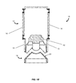
- FIG. 7 is a perspective view of an example of an omni-directional satellite speaker system having a pair of acoustic drivers and a pair of omni-directional acoustic deflectors to reduce the negative effects of resonances on the acoustic spectrum according to principles described herein.
- omni-directional speaker systems Multiple benefits are known for omni-directional speaker systems. These benefits include a more spacious sound image when the speaker system is placed near a boundary, such as a wall within a room, due to reflections. Another benefit is that the speaker system does not have to be oriented in a particular direction to achieve optimum high frequency coverage. This second advantage is highly desirable for mobile speaker systems where the speaker system and/or the listener may be moving.
- FIGS. 1A, 1B and 1C are drawings showing a perspective view, cross-sectional view and perspective cut-away view, respectively, of a speaker system 10 that includes a single downward firing acoustic driver 12 secured to a vertical acoustic enclosure 14 .
- Each side wall 15 of the enclosure 14 includes a passive radiator 16 .
- two opposing passive radiators 16 are configured to be driven by audio signals from an audio source (not shown) such that each opposing pair of passive radiators 16 are driven acoustically in phase with each other and mechanically out of phase with each other, to minimize vibration of the enclosure 14 .
- Two opposing pairs of passive radiators 16 may be used, as shown in the figures.
- the passive radiators 16 may be located on an outer wall 15 of the enclosure 14 , as depicted, or instead be located within the enclosure 14 and configured to radiate acoustic energy through slots located in the enclosure 14 (not shown).
- One or more of the passive radiators 16 may be oriented vertically or horizontally within the enclosure 14 .
- the volume within the region above the acoustic driver 12 and inside the enclosure 14 as “sealed” with the passive radiators 16 , defines an acoustic chamber.
- the diaphragms of the passive radiators 16 are driven by pressure changes within the acoustic chamber.
- the speaker system 10 also includes an omni-directional acoustic deflector 18 having four vertical legs 19 to which the enclosure 14 is mounted.
- Acoustic energy generated by the acoustic driver 12 propagates downward and is deflected into a nominal horizontal direction by a substantially conical outer surface 22 of the inner portion of the acoustic deflector 18 .
- Each opening 20 is defined by the base of the enclosure 14 , the base of the acoustic deflector 18 and a pair of the vertical legs 19 .
- These four openings 20 are acoustic apertures which pass the horizontally propagating acoustic energy. It should be understood that the propagation of the acoustic energy in a given direction includes a spreading of the propagating acoustic energy, for example, due to diffraction.
- FIG. 2 is a perspective view of the omni-directional acoustic deflector 18 showing the conical outer surface 22 and a top surface 24 .
- FIG. 3A and FIG. 3B show a cross-sectional view and a perspective cut-away perspective view, respectively, of the omni-directional acoustic deflector 18 and the acoustic driver 12 .
- the top surface 24 of the acoustic deflector 18 is shaped to accommodate the excursions of a central dust cap 25 , centered on the face 27 of the acoustic driver 12 , during operation of the speaker system.
- the conventional conical shape of the acoustic deflector 18 results in significant colorization of the acoustic spectrum, especially at higher acoustic frequencies as shown by the dashed curve 26 in FIG. 4 , due to resonances in the volume between the face 27 and dust cap 25 of the acoustic driver 12 and the conical outer surface 22 and top surface 24 of the acoustic deflector 18 .
- FIGS. 5A, 5B and 5C are illustrations showing a perspective view, cross-sectional view and perspective cut-away view, respectively, of an example of an omni-directional speaker system 50 having an omni-directional acoustic deflector 30 disposed below a single downward firing acoustic driver 12 .
- the omni-directional acoustic deflector 30 is configured to reduce the negative effects of resonances on the acoustic spectrum as described below.
- the illustrated speaker system 50 is substantially similar to the speaker system 10 shown in FIGS. 1A, 1B and 1C except for the omni-directional acoustic deflector 30 which has different structural and material features.
- FIG. 6A is a perspective view of the omni-directional acoustic deflector 30 and includes regions having acoustically absorbing material 44 as described below.
- FIG. 6B is a cut-away perspective view of the omni-directional acoustic deflector 30 shown without the absorbing material 44 .
- the solid curve 28 shows the acoustic spectrum that is achieved with the illustrated omni-directional speaker system 50 with the acoustic deflector 30 .
- a comparison with the dashed curve 26 which represents the acoustic spectrum for the speaker system 10 having the omni-directional acoustic deflector 18 of FIG. 2 , demonstrates the improved performance (i.e., flatter spectrum) resulting from use of the acoustic deflector 30 . Performance at longer acoustic wavelengths (e.g., frequencies below approximately 1 KHz) is not significantly different.
- the illustrated acoustic deflector 30 has a nominal truncated conical shape.
- the slope of the conical outer surface 32 between the base and vertex of the cone is not constant.
- the surface 32 may have a non-linear slant profile such as a parabolic profile or a profile described by a truncated hyperboloid of revolution.
- the body of the acoustic deflector 30 can be made of any suitably acoustically reflective material.
- the body may be formed from plastic, stone, metal or other rigid material, or any suitable combinations thereof.
- the omni-directional acoustic deflector 30 includes two features which contribute to the improvement in the acoustic spectrum.
- the numbers of legs 38 and extensions 34 , or other features radially extending from the axis (vertical dashed line 40 ) of the cone are different.
- the second feature of the omni-directional acoustic deflector 30 that results in an improvement in the acoustic spectrum is the presence of acoustically absorbing regions disposed along the acoustically reflective surface.
- FIG. 6B shows one of these regions at an opening 42 centered on the cone axis 40 at the top of the truncated cone in which acoustically absorbing material 44 is disposed ( FIG. 6A ).
- This acoustically absorbing material 44 attenuates the acoustic energy present near and at the peak of the lowest order circularly symmetric resonance mode.
- the diameter of the opening 42 is chosen so that the resulting attenuation of the acoustic energy propagating from the speaker 12 is limited to an acceptable level while achieving a desirable level of smoothing of the acoustic spectrum.
- Additional openings 46 in the form of slots, each containing acoustically absorbing material 44 are located along portions of a circumference of the nominal conical outer surface 32 .
- the circumference is at a cone radius that corresponds to a pressure maximum of a circularly symmetric acoustic resonance mode.
- the circumference may be at a peak of the second harmonic of the resonance mode.
- the circumference is at a radius that is approximately one-half the base radius of the cone.
- the radial extensions 34 extend from the mounting surfaces 36 to the nominal conical outer surface 32 below the circumference of the slotted openings 46 to thereby permit a single opening extending 360° along the circumference.
- upper and lower portions of the conical outer surface 32 are separated by the single opening.
- one or more structural features inside the body cavity may be used to support the upper portion.
- the acoustically absorbing material 44 is a foam.
- the open region in the body cavity of the acoustic deflector 30 shown in FIG. 6B beneath the cone, is filled with a single volume of foam such that the foam is adjacent to, or extends into, the openings 42 and 46 .
- a separate foam element may be disposed at each opening 42 and 46 so that only a portion of the body cavity is occupied by foam.
- the foam is coated with a water resistant material.
- the foam present at the central opening 42 is at one end of a cylindrically-shaped foam element disposed within the body cavity.
- the acoustically absorbing material 44 is an acoustically absorbing fabric or screen.
- the fabric may be disposed within the openings 42 and 46 or inside the internal cavity of the cone adjacent to each opening 42 or 46 .
- the fabric is acoustically transparent to a degree; however, the acoustic resistance can be tune by using different fabrics.
- the fabric avoids the need for using one or more large volumes of foam as the inside surface of the conical portion of the acoustic deflector body (opposite surface 32 ) can be lined with the fabric.
- the fabric can be water resistant without the need to apply a water resistant coating.
- a suitable fabric for some implementations is Saatifil Acoustex 145 available from SaatiTech U.S.A. of Somers, N.Y.
- an omni-directional satellite speaker system 60 includes a pair of acoustic drivers. Each acoustic driver is secured inside a vertical acoustic enclosure 62 . One of the acoustic drivers is configured to provide acoustic energy in an upward direction and the other acoustic driver is positioned to face in an opposite direction so that acoustic energy propagates in a downward direction.
- the system also includes two omni-directional acoustic deflectors 64 , each positioned near the face of a respective one of the acoustic drivers and having acoustic acoustically absorbing material as described in the various examples above.
- the omni-directional satellite speaker system 60 includes two speaker subsystems, each similar to the speaker system 50 shown in FIG. 5A .
- One of the speaker subsystems is vertically inverted and adjacent to the other speaker subsystem.
- An omni-directional satellite speaker system configured in this way can employ smaller active drivers to achieve the same acoustic output of a single active driver system and therefore can have a smaller footprint.
- omni-directional acoustic deflectors act as an acoustic smoothing filter by providing a modified acoustic resonance volume between the speaker and the acoustic deflector. It will be appreciated that adjusting the size and locations of the acoustically absorbing regions allows for the acoustic spectrum to be tuned to modify the acoustic spectrum.
- the profile of the acoustically reflecting surface may be non-linear (i.e., vary from a perfect conical surface) and defined so as to modify the acoustic spectrum.
- non-circularly symmetric extensions in the acoustically reflecting surface such as the radial extensions described above, can be utilized to achieve an acceptable acoustic spectrum.
Landscapes
- Health & Medical Sciences (AREA)
- Otolaryngology (AREA)
- Physics & Mathematics (AREA)
- Engineering & Computer Science (AREA)
- Acoustics & Sound (AREA)
- Signal Processing (AREA)
- Obtaining Desirable Characteristics In Audible-Bandwidth Transducers (AREA)
- Details Of Audible-Bandwidth Transducers (AREA)
Abstract
Description
Claims (18)
Priority Applications (1)
| Application Number | Priority Date | Filing Date | Title |
|---|---|---|---|
| US15/366,755 US9883283B2 (en) | 2015-01-31 | 2016-12-01 | Acoustic deflector for omni-directional speaker system |
Applications Claiming Priority (3)
| Application Number | Priority Date | Filing Date | Title |
|---|---|---|---|
| US201562110493P | 2015-01-31 | 2015-01-31 | |
| US14/643,216 US9544681B2 (en) | 2015-01-31 | 2015-03-10 | Acoustic deflector for omni-directional speaker system |
| US15/366,755 US9883283B2 (en) | 2015-01-31 | 2016-12-01 | Acoustic deflector for omni-directional speaker system |
Related Parent Applications (1)
| Application Number | Title | Priority Date | Filing Date |
|---|---|---|---|
| US14/643,216 Continuation US9544681B2 (en) | 2015-01-31 | 2015-03-10 | Acoustic deflector for omni-directional speaker system |
Related Child Applications (1)
| Application Number | Title | Priority Date | Filing Date |
|---|---|---|---|
| US17/067,696 Division US20210029446A1 (en) | 2016-04-12 | 2020-10-11 | Organic light-emitting diode display device and method of manufacturing the same |
Publications (2)
| Publication Number | Publication Date |
|---|---|
| US20170085983A1 US20170085983A1 (en) | 2017-03-23 |
| US9883283B2 true US9883283B2 (en) | 2018-01-30 |
Family
ID=55359746
Family Applications (2)
| Application Number | Title | Priority Date | Filing Date |
|---|---|---|---|
| US14/643,216 Active 2035-04-24 US9544681B2 (en) | 2015-01-31 | 2015-03-10 | Acoustic deflector for omni-directional speaker system |
| US15/366,755 Active US9883283B2 (en) | 2015-01-31 | 2016-12-01 | Acoustic deflector for omni-directional speaker system |
Family Applications Before (1)
| Application Number | Title | Priority Date | Filing Date |
|---|---|---|---|
| US14/643,216 Active 2035-04-24 US9544681B2 (en) | 2015-01-31 | 2015-03-10 | Acoustic deflector for omni-directional speaker system |
Country Status (5)
| Country | Link |
|---|---|
| US (2) | US9544681B2 (en) |
| EP (1) | EP3251378B1 (en) |
| JP (1) | JP6553732B2 (en) |
| CN (1) | CN107431854B (en) |
| WO (1) | WO2016123428A1 (en) |
Cited By (5)
| Publication number | Priority date | Publication date | Assignee | Title |
|---|---|---|---|---|
| US10462562B1 (en) * | 2017-11-15 | 2019-10-29 | Todd F. Rady | Prime polygon reflectors and methods of use |
| US10462561B2 (en) * | 2011-07-15 | 2019-10-29 | Kpo Innovation Ab | Audio generator including a reflector with a non-flat contour |
| US11128951B1 (en) * | 2018-11-13 | 2021-09-21 | Todd F. Rady | Prime polygon reflectors and methods of use |
| US20210382300A1 (en) * | 2017-11-15 | 2021-12-09 | Todd F. Rady | Prime polygon reflectors and methods of use |
| US20230393314A1 (en) * | 2017-11-15 | 2023-12-07 | Todd Francis Rady | Prime polygon reflectors and methods of use |
Families Citing this family (34)
| Publication number | Priority date | Publication date | Assignee | Title |
|---|---|---|---|---|
| US9883282B2 (en) * | 2015-01-31 | 2018-01-30 | Bose Corporation | Acoustic deflector for omni-directional speaker system |
| US9544681B2 (en) * | 2015-01-31 | 2017-01-10 | Bose Corporation | Acoustic deflector for omni-directional speaker system |
| US10397696B2 (en) | 2015-01-31 | 2019-08-27 | Bose Corporation | Omni-directional speaker system and related devices and methods |
| US10034081B2 (en) * | 2015-09-28 | 2018-07-24 | Samsung Electronics Co., Ltd. | Acoustic filter for omnidirectional loudspeaker |
| US10469942B2 (en) | 2015-09-28 | 2019-11-05 | Samsung Electronics Co., Ltd. | Three hundred and sixty degree horn for omnidirectional loudspeaker |
| KR102352365B1 (en) * | 2015-11-17 | 2022-01-18 | 삼성전자주식회사 | Speaker device and electronic device including the same |
| US10299035B2 (en) | 2015-12-30 | 2019-05-21 | Harman International Industries, Incorporated | Acoustic lens system for loudspeakers |
| EP3466099A4 (en) * | 2016-06-02 | 2020-02-12 | Hewlett-Packard Development Company, L.P. | Heat and sound deflector |
| KR102473082B1 (en) * | 2016-07-04 | 2022-12-02 | 삼성전자주식회사 | Speaker device |
| JP2019531649A (en) | 2016-09-12 | 2019-10-31 | ボーズ・コーポレーションBosecorporation | Speaker system |
| US10341761B2 (en) | 2017-02-17 | 2019-07-02 | Tymphany Hk Limited | Acoustic waveguide for audio speaker |
| US10306356B2 (en) * | 2017-03-31 | 2019-05-28 | Bose Corporation | Acoustic deflector as heat sink |
| US10643599B2 (en) * | 2017-06-29 | 2020-05-05 | Harman International Industries, Incorporated | Acoustic lens for a transducer |
| USD872054S1 (en) | 2017-08-04 | 2020-01-07 | Bose Corporation | Speaker |
| US10425739B2 (en) * | 2017-10-03 | 2019-09-24 | Bose Corporation | Acoustic deflector with convective cooling |
| KR102367386B1 (en) * | 2017-10-30 | 2022-02-25 | 삼성전자주식회사 | Speaker and operation method thereof |
| JP7069715B2 (en) | 2017-12-28 | 2022-05-18 | 株式会社Jvcケンウッド | Speaker |
| KR101975975B1 (en) * | 2018-02-02 | 2019-05-08 | (주)인포마크 | Omni-directional Speaker Having Band-Shaped Passive Radiator |
| KR101975978B1 (en) * | 2018-02-02 | 2019-05-08 | (주)인포마크 | Omni-directional Speaker Having Full Cover Type Passive Radiator |
| KR101975973B1 (en) * | 2018-02-02 | 2019-05-08 | (주)인포마크 | Omni-directional Speaker Having Side-Mounting Type Passive Radiator |
| CN108471577B (en) * | 2018-03-28 | 2021-05-18 | 汉桑(南京)科技有限公司 | Acoustic device |
| CN110392323A (en) * | 2018-04-19 | 2019-10-29 | 惠州迪芬尼声学科技股份有限公司 | Loudspeaker and its acoustic diffusers |
| CN109803215B (en) * | 2018-12-18 | 2021-01-22 | 歌尔股份有限公司 | Acoustic device and electronic apparatus |
| US10812884B2 (en) * | 2019-01-10 | 2020-10-20 | Ms Electronics, Llc | Hanging speaker system |
| US10448148B1 (en) * | 2019-01-10 | 2019-10-15 | Ms Electronics, Llc | Hanging speaker system |
| US10694280B1 (en) * | 2019-01-10 | 2020-06-23 | MS Electronics LLC | Hanging speaker system |
| US10595120B1 (en) * | 2019-01-10 | 2020-03-17 | MS Electronics LLC | Hanging speaker system |
| US10770047B2 (en) | 2019-01-15 | 2020-09-08 | Bose Corporation | Electric musical instrument having rear mounted speaker |
| JP7212264B2 (en) * | 2019-01-17 | 2023-01-25 | オンキヨー株式会社 | Diffuser, speaker and electronic musical instrument equipped with same |
| US11277684B2 (en) | 2019-01-17 | 2022-03-15 | Onkyo Corporation | Diffuser |
| CN114556967A (en) * | 2019-10-10 | 2022-05-27 | 哈曼国际工业有限公司 | Side-firing headrest speaker with omnidirectional lens |
| CN110856058B (en) * | 2019-11-28 | 2021-03-19 | 歌尔股份有限公司 | Loudspeaker and electronic equipment with same |
| TWI734382B (en) * | 2020-02-17 | 2021-07-21 | 大陸商東莞寶德電子有限公司 | Annular radiation speaker structure |
| US12418744B2 (en) | 2023-08-29 | 2025-09-16 | Roswell U.S., LLC | Speaker with sound dispersing cone |
Citations (29)
| Publication number | Priority date | Publication date | Assignee | Title |
|---|---|---|---|---|
| US3912866A (en) * | 1974-01-30 | 1975-10-14 | Showsound Inc | Folded bass horn speaker |
| US4322578A (en) * | 1977-09-06 | 1982-03-30 | Society Ap Selmin Sas Of Massimo Coltelli & Co. | Method and devices for the omnidirectional radiation of sound waves |
| US4348549A (en) * | 1978-02-06 | 1982-09-07 | Emmanuel Berlant | Loudspeaker system |
| US4620317A (en) | 1984-04-05 | 1986-10-28 | Shure Brothers, Inc. | Tabletop speaker assembly |
| US5115882A (en) * | 1989-03-29 | 1992-05-26 | Woody D Grier | Omnidirectional dispersion system for multiway loudspeakers |
| EP0518668A2 (en) | 1991-06-12 | 1992-12-16 | Sonic Systems, Inc. | Hemispherically wide-radiating-angle loudspeaker system |
| US5306880A (en) * | 1991-06-25 | 1994-04-26 | Eclipse Research Corporation | Omnidirectional speaker system |
| US6009972A (en) * | 1997-10-10 | 2000-01-04 | Samsung Electronics Co., Ltd. | Omni-directional speaker system |
| US6026928A (en) * | 1999-04-06 | 2000-02-22 | Maharaj; Ashok A. | Apparatus and method for reduced distortion loudspeakers |
| US6064744A (en) | 1997-04-18 | 2000-05-16 | Augustin; Heinz-Juergen | Omni-directional loudspeaker |
| US6257365B1 (en) * | 1996-08-30 | 2001-07-10 | Mediaphile Av Technologies, Inc. | Cone reflector/coupler speaker system and method |
| US20020011379A1 (en) | 2000-06-21 | 2002-01-31 | Taylor Ronald K. | Speaker enclosure venturi expander |
| US6597797B1 (en) * | 1999-06-23 | 2003-07-22 | Sonic Systems, Inc. | Spherical loudspeaker system with enhanced performance |
| US20030141142A1 (en) | 2002-01-25 | 2003-07-31 | Carl Christiansen | Garden speaker |
| US20080192972A1 (en) * | 2007-02-13 | 2008-08-14 | Vernon Lewallen | Phasing plug for acoustic compression drivers |
| US20090245561A1 (en) | 2008-03-27 | 2009-10-01 | Bose Corporation | Acoustic Passive Radiating |
| US20090310808A1 (en) | 2008-06-17 | 2009-12-17 | Harman International Industries, Incorporated | Waveguide |
| US20120076328A1 (en) | 2010-09-23 | 2012-03-29 | Ronald Paul Harwood | Acoustic reflector |
| US8181736B2 (en) * | 2008-08-14 | 2012-05-22 | Harman International Industries, Incorporated | Phase plug and acoustic lens for direct radiating loudspeaker |
| US20120201403A1 (en) | 2009-10-30 | 2012-08-09 | Dream Infotainment Resources Pte Ltd | Omnidirectional speaker |
| DE102011016326A1 (en) | 2011-04-01 | 2012-10-04 | Kerstin Brachaus | Loudspeaker arrangement has tip ends of cone-shaped portions that are directed towards corresponding speaker unit, and surfaces of cone-shaped portions that are enlarged by recess portions and projections |
| US8290195B2 (en) * | 2010-03-31 | 2012-10-16 | Bose Corporation | Acoustic radiation pattern adjusting |
| US8467557B2 (en) * | 2009-09-24 | 2013-06-18 | MS Electronics LLC | Coaxial speaker system with improved transition between individual speakers |
| US20140321686A1 (en) * | 2012-04-26 | 2014-10-30 | Adam Stephen Wegener | Sound System Using Repurposed Materials |
| US9282398B2 (en) * | 2014-03-19 | 2016-03-08 | Dana Monroe | Speaker system having wide bandwidth and wide high-frequency dispersion |
| US20160227315A1 (en) * | 2015-01-31 | 2016-08-04 | Bose Corporation | Acoustic deflector for omni-directional speaker system |
| US20160337748A1 (en) * | 2015-01-31 | 2016-11-17 | Bose Corporation | Acoustic deflector for omni-directional speaker system |
| US20170006376A1 (en) | 2013-12-20 | 2017-01-05 | Dream Audiolab Pte Ltd | Improved Omnidirectional Speaker With Soundwave Deflectors |
| US20170094403A1 (en) * | 2015-09-28 | 2017-03-30 | Samsung Electronics Co., Ltd. | Acoustic filter for omnidirectional loudspeaker |
Family Cites Families (7)
| Publication number | Priority date | Publication date | Assignee | Title |
|---|---|---|---|---|
| JPS5124242Y2 (en) * | 1971-10-07 | 1976-06-22 | ||
| JPS543930U (en) * | 1977-06-10 | 1979-01-11 | ||
| JPS61264897A (en) * | 1985-05-20 | 1986-11-22 | Mitsubishi Electric Corp | speaker device |
| JPS61264896A (en) * | 1985-05-20 | 1986-11-22 | Mitsubishi Electric Corp | Reflection type speaker system |
| JP2009141657A (en) * | 2007-12-06 | 2009-06-25 | Pioneer Electronic Corp | Speaker apparatus |
| JP2010093767A (en) * | 2008-10-07 | 2010-04-22 | Junichi Kakumoto | Loudspeaker system |
| DE102010021879A1 (en) * | 2010-05-28 | 2011-12-01 | Frank Held | Loudspeaker device with circumferential, funnel-shaped sound outlet opening |
-
2015
- 2015-03-10 US US14/643,216 patent/US9544681B2/en active Active
-
2016
- 2016-01-29 CN CN201680014719.8A patent/CN107431854B/en active Active
- 2016-01-29 EP EP16704759.6A patent/EP3251378B1/en active Active
- 2016-01-29 JP JP2017540127A patent/JP6553732B2/en active Active
- 2016-01-29 WO PCT/US2016/015521 patent/WO2016123428A1/en not_active Ceased
- 2016-12-01 US US15/366,755 patent/US9883283B2/en active Active
Patent Citations (35)
| Publication number | Priority date | Publication date | Assignee | Title |
|---|---|---|---|---|
| US3912866A (en) * | 1974-01-30 | 1975-10-14 | Showsound Inc | Folded bass horn speaker |
| US4322578A (en) * | 1977-09-06 | 1982-03-30 | Society Ap Selmin Sas Of Massimo Coltelli & Co. | Method and devices for the omnidirectional radiation of sound waves |
| US4348549A (en) * | 1978-02-06 | 1982-09-07 | Emmanuel Berlant | Loudspeaker system |
| US4620317A (en) | 1984-04-05 | 1986-10-28 | Shure Brothers, Inc. | Tabletop speaker assembly |
| US5115882A (en) * | 1989-03-29 | 1992-05-26 | Woody D Grier | Omnidirectional dispersion system for multiway loudspeakers |
| EP0518668A2 (en) | 1991-06-12 | 1992-12-16 | Sonic Systems, Inc. | Hemispherically wide-radiating-angle loudspeaker system |
| US5268538A (en) | 1991-06-12 | 1993-12-07 | Sonic Systems, Inc. | Hemispherically wide-radiating-angle loudspeaker system |
| US5306880A (en) * | 1991-06-25 | 1994-04-26 | Eclipse Research Corporation | Omnidirectional speaker system |
| US6257365B1 (en) * | 1996-08-30 | 2001-07-10 | Mediaphile Av Technologies, Inc. | Cone reflector/coupler speaker system and method |
| US6064744A (en) | 1997-04-18 | 2000-05-16 | Augustin; Heinz-Juergen | Omni-directional loudspeaker |
| US6009972A (en) * | 1997-10-10 | 2000-01-04 | Samsung Electronics Co., Ltd. | Omni-directional speaker system |
| US6026928A (en) * | 1999-04-06 | 2000-02-22 | Maharaj; Ashok A. | Apparatus and method for reduced distortion loudspeakers |
| US6597797B1 (en) * | 1999-06-23 | 2003-07-22 | Sonic Systems, Inc. | Spherical loudspeaker system with enhanced performance |
| US20020011379A1 (en) | 2000-06-21 | 2002-01-31 | Taylor Ronald K. | Speaker enclosure venturi expander |
| US20030141142A1 (en) | 2002-01-25 | 2003-07-31 | Carl Christiansen | Garden speaker |
| US20080192972A1 (en) * | 2007-02-13 | 2008-08-14 | Vernon Lewallen | Phasing plug for acoustic compression drivers |
| US20090245561A1 (en) | 2008-03-27 | 2009-10-01 | Bose Corporation | Acoustic Passive Radiating |
| US8130994B2 (en) * | 2008-06-17 | 2012-03-06 | Harman International Industries, Incorporated | Waveguide |
| US20090310808A1 (en) | 2008-06-17 | 2009-12-17 | Harman International Industries, Incorporated | Waveguide |
| US8418802B2 (en) * | 2008-08-14 | 2013-04-16 | Harman International Industries, Incorporated | Phase plug and acoustic lens for direct radiating loudspeaker |
| US8672088B2 (en) * | 2008-08-14 | 2014-03-18 | Harman International Industries, Inc. | Phase plug and acoustic lens for direct radiating loudspeaker |
| US8181736B2 (en) * | 2008-08-14 | 2012-05-22 | Harman International Industries, Incorporated | Phase plug and acoustic lens for direct radiating loudspeaker |
| US20130228393A1 (en) | 2008-08-14 | 2013-09-05 | Harman International Industries, Incorporated | Phase plug and acoustic lens for direct radiating loudspeaker |
| US8467557B2 (en) * | 2009-09-24 | 2013-06-18 | MS Electronics LLC | Coaxial speaker system with improved transition between individual speakers |
| US20120201403A1 (en) | 2009-10-30 | 2012-08-09 | Dream Infotainment Resources Pte Ltd | Omnidirectional speaker |
| US8750540B2 (en) * | 2009-10-30 | 2014-06-10 | Dream Audiolab Pte. Ltd. | Omnidirectional speaker |
| US8290195B2 (en) * | 2010-03-31 | 2012-10-16 | Bose Corporation | Acoustic radiation pattern adjusting |
| US20120076328A1 (en) | 2010-09-23 | 2012-03-29 | Ronald Paul Harwood | Acoustic reflector |
| DE102011016326A1 (en) | 2011-04-01 | 2012-10-04 | Kerstin Brachaus | Loudspeaker arrangement has tip ends of cone-shaped portions that are directed towards corresponding speaker unit, and surfaces of cone-shaped portions that are enlarged by recess portions and projections |
| US20140321686A1 (en) * | 2012-04-26 | 2014-10-30 | Adam Stephen Wegener | Sound System Using Repurposed Materials |
| US20170006376A1 (en) | 2013-12-20 | 2017-01-05 | Dream Audiolab Pte Ltd | Improved Omnidirectional Speaker With Soundwave Deflectors |
| US9282398B2 (en) * | 2014-03-19 | 2016-03-08 | Dana Monroe | Speaker system having wide bandwidth and wide high-frequency dispersion |
| US20160227315A1 (en) * | 2015-01-31 | 2016-08-04 | Bose Corporation | Acoustic deflector for omni-directional speaker system |
| US20160337748A1 (en) * | 2015-01-31 | 2016-11-17 | Bose Corporation | Acoustic deflector for omni-directional speaker system |
| US20170094403A1 (en) * | 2015-09-28 | 2017-03-30 | Samsung Electronics Co., Ltd. | Acoustic filter for omnidirectional loudspeaker |
Non-Patent Citations (7)
| Title |
|---|
| International Search Report and Written Opinion dated Apr. 7, 2016 for International application No. PCT/US2016/015521. |
| International Search Report and Written Opinion dated Apr. 7, 2017 for International application No. PCT/US2016/044682. |
| International Search Report and Written Opinion dated Jun. 28, 2017 for International application No. PCT/US2016/044680. |
| Invitation to Pay Additional Fees dated Apr. 5, 2017 for International application No. PCT/US2016/044680. |
| McRitchie, Don, "Aquarius: A Noble Experiment", Audioheritage.com, 2001, accesses Mar. 5, 2015, 9 pages. |
| Visaton-Der Lautsprecherspezialist: "Kegel fur Rundstrahler", Apr. 8, 2012, pp. 1-8, XP055383099, retrieved from the Internet URL:http://www.visaton.de/vb/showthread.php?t=235448,highlight=f%C3YDBC11 en [retrieved on Jun. 20, 2017], p. 2-"Henrik" dialog input, p. 3-"walwal" 1st dialog input, p. 5-"walwal" dialog input. |
| Visaton—Der Lautsprecherspezialist: "Kegel fur Rundstrahler", Apr. 8, 2012, pp. 1-8, XP055383099, retrieved from the Internet URL:http://www.visaton.de/vb/showthread.php?t=235448,highlight=f%C3YDBC11 en [retrieved on Jun. 20, 2017], p. 2—"Henrik" dialog input, p. 3—"walwal" 1st dialog input, p. 5—"walwal" dialog input. |
Cited By (7)
| Publication number | Priority date | Publication date | Assignee | Title |
|---|---|---|---|---|
| US10462561B2 (en) * | 2011-07-15 | 2019-10-29 | Kpo Innovation Ab | Audio generator including a reflector with a non-flat contour |
| US10462562B1 (en) * | 2017-11-15 | 2019-10-29 | Todd F. Rady | Prime polygon reflectors and methods of use |
| US20210382300A1 (en) * | 2017-11-15 | 2021-12-09 | Todd F. Rady | Prime polygon reflectors and methods of use |
| US11630298B2 (en) * | 2017-11-15 | 2023-04-18 | Todd F. Rady | Prime polygon reflectors and methods of use |
| US20230393314A1 (en) * | 2017-11-15 | 2023-12-07 | Todd Francis Rady | Prime polygon reflectors and methods of use |
| US12366688B2 (en) * | 2017-11-15 | 2025-07-22 | Todd Francis Rady | Prime polygon reflectors and methods of use |
| US11128951B1 (en) * | 2018-11-13 | 2021-09-21 | Todd F. Rady | Prime polygon reflectors and methods of use |
Also Published As
| Publication number | Publication date |
|---|---|
| JP6553732B2 (en) | 2019-07-31 |
| EP3251378A1 (en) | 2017-12-06 |
| US20170085983A1 (en) | 2017-03-23 |
| CN107431854B (en) | 2020-01-07 |
| JP2018504056A (en) | 2018-02-08 |
| US20160227315A1 (en) | 2016-08-04 |
| WO2016123428A1 (en) | 2016-08-04 |
| EP3251378B1 (en) | 2018-11-21 |
| US9544681B2 (en) | 2017-01-10 |
| CN107431854A (en) | 2017-12-01 |
Similar Documents
| Publication | Publication Date | Title |
|---|---|---|
| US9883283B2 (en) | Acoustic deflector for omni-directional speaker system | |
| US9883282B2 (en) | Acoustic deflector for omni-directional speaker system | |
| US10911865B2 (en) | Omni-directional speaker system and related devices and methods | |
| US5253301A (en) | Nondirectional acoustic generator and speaker system | |
| KR101192910B1 (en) | Phase plug and acoustic lens for direct radiating loudspeaker | |
| US8280091B2 (en) | Dual compression drivers and phasing plugs for compression drivers | |
| US3327808A (en) | Loud speaker housing | |
| KR102130365B1 (en) | Loudspeaker | |
| US6064746A (en) | Piezoelectric speaker | |
| KR20150004643A (en) | Sound generation apparatus and electric apparatus comprising thereof | |
| US20190058954A1 (en) | Layered speaker assembly | |
| US6055320A (en) | Directional horn speaker system | |
| EP3371982B1 (en) | Acoustic deflector for omni-directional speaker system | |
| US2815823A (en) | Loudspeaker structure | |
| EP3292701B1 (en) | Omni-directional speaker system and related devices and methods | |
| US11647326B2 (en) | Loudspeakers | |
| GB2573056A (en) | Speaker and sound diffuser thereof | |
| GB2509711A (en) | Selective or frequency-dependent acoustic damping | |
| US20230018951A1 (en) | Sound diffraction reduction speaker incorporating meta material | |
| US2734591A (en) | Loudspeaker structure | |
| CN113966621B (en) | Low profile speakers | |
| JP2020178147A (en) | Ceiling embedded speaker |
Legal Events
| Date | Code | Title | Description |
|---|---|---|---|
| AS | Assignment |
Owner name: BOSE CORPORATION, MASSACHUSETTS Free format text: ASSIGNMENT OF ASSIGNORS INTEREST;ASSIGNORS:KIM, WONTAK;CHUTE, GEORGE E.P.;REEL/FRAME:040537/0646 Effective date: 20150515 |
|
| STCF | Information on status: patent grant |
Free format text: PATENTED CASE |
|
| MAFP | Maintenance fee payment |
Free format text: PAYMENT OF MAINTENANCE FEE, 4TH YEAR, LARGE ENTITY (ORIGINAL EVENT CODE: M1551); ENTITY STATUS OF PATENT OWNER: LARGE ENTITY Year of fee payment: 4 |
|
| AS | Assignment |
Owner name: BANK OF AMERICA, N.A., AS ADMINISTRATIVE AGENT, MASSACHUSETTS Free format text: SECURITY INTEREST;ASSIGNOR:BOSE CORPORATION;REEL/FRAME:070438/0001 Effective date: 20250228 |
|
| MAFP | Maintenance fee payment |
Free format text: PAYMENT OF MAINTENANCE FEE, 8TH YEAR, LARGE ENTITY (ORIGINAL EVENT CODE: M1552); ENTITY STATUS OF PATENT OWNER: LARGE ENTITY Year of fee payment: 8 |