US9882816B2 - Method of mapping CSI-RS ports to resource blocks, base station and user equipment - Google Patents
Method of mapping CSI-RS ports to resource blocks, base station and user equipment Download PDFInfo
- Publication number
- US9882816B2 US9882816B2 US14/779,553 US201314779553A US9882816B2 US 9882816 B2 US9882816 B2 US 9882816B2 US 201314779553 A US201314779553 A US 201314779553A US 9882816 B2 US9882816 B2 US 9882816B2
- Authority
- US
- United States
- Prior art keywords
- ports
- csi
- group
- transmission period
- resource blocks
- Prior art date
- Legal status (The legal status is an assumption and is not a legal conclusion. Google has not performed a legal analysis and makes no representation as to the accuracy of the status listed.)
- Active, expires
Links
Images


Classifications
-
- H—ELECTRICITY
- H04—ELECTRIC COMMUNICATION TECHNIQUE
- H04L—TRANSMISSION OF DIGITAL INFORMATION, e.g. TELEGRAPHIC COMMUNICATION
- H04L47/00—Traffic control in data switching networks
- H04L47/10—Flow control; Congestion control
- H04L47/12—Avoiding congestion; Recovering from congestion
- H04L47/125—Avoiding congestion; Recovering from congestion by balancing the load, e.g. traffic engineering
-
- H—ELECTRICITY
- H04—ELECTRIC COMMUNICATION TECHNIQUE
- H04B—TRANSMISSION
- H04B7/00—Radio transmission systems, i.e. using radiation field
- H04B7/02—Diversity systems; Multi-antenna system, i.e. transmission or reception using multiple antennas
- H04B7/04—Diversity systems; Multi-antenna system, i.e. transmission or reception using multiple antennas using two or more spaced independent antennas
- H04B7/0413—MIMO systems
-
- H—ELECTRICITY
- H04—ELECTRIC COMMUNICATION TECHNIQUE
- H04L—TRANSMISSION OF DIGITAL INFORMATION, e.g. TELEGRAPHIC COMMUNICATION
- H04L5/00—Arrangements affording multiple use of the transmission path
- H04L5/0001—Arrangements for dividing the transmission path
- H04L5/0014—Three-dimensional division
- H04L5/0023—Time-frequency-space
-
- H—ELECTRICITY
- H04—ELECTRIC COMMUNICATION TECHNIQUE
- H04L—TRANSMISSION OF DIGITAL INFORMATION, e.g. TELEGRAPHIC COMMUNICATION
- H04L5/00—Arrangements affording multiple use of the transmission path
- H04L5/003—Arrangements for allocating sub-channels of the transmission path
- H04L5/0048—Allocation of pilot signals, i.e. of signals known to the receiver
-
- H—ELECTRICITY
- H04—ELECTRIC COMMUNICATION TECHNIQUE
- H04L—TRANSMISSION OF DIGITAL INFORMATION, e.g. TELEGRAPHIC COMMUNICATION
- H04L5/00—Arrangements affording multiple use of the transmission path
- H04L5/003—Arrangements for allocating sub-channels of the transmission path
- H04L5/0058—Allocation criteria
- H04L5/0064—Rate requirement of the data, e.g. scalable bandwidth, data priority
-
- H—ELECTRICITY
- H04—ELECTRIC COMMUNICATION TECHNIQUE
- H04L—TRANSMISSION OF DIGITAL INFORMATION, e.g. TELEGRAPHIC COMMUNICATION
- H04L5/00—Arrangements affording multiple use of the transmission path
- H04L5/003—Arrangements for allocating sub-channels of the transmission path
- H04L5/0078—Timing of allocation
- H04L5/0085—Timing of allocation when channel conditions change
-
- H—ELECTRICITY
- H04—ELECTRIC COMMUNICATION TECHNIQUE
- H04W—WIRELESS COMMUNICATION NETWORKS
- H04W88/00—Devices specially adapted for wireless communication networks, e.g. terminals, base stations or access point devices
- H04W88/08—Access point devices
-
- H—ELECTRICITY
- H04—ELECTRIC COMMUNICATION TECHNIQUE
- H04L—TRANSMISSION OF DIGITAL INFORMATION, e.g. TELEGRAPHIC COMMUNICATION
- H04L5/00—Arrangements affording multiple use of the transmission path
- H04L5/0091—Signaling for the administration of the divided path
- H04L5/0096—Indication of changes in allocation
-
- H—ELECTRICITY
- H04—ELECTRIC COMMUNICATION TECHNIQUE
- H04W—WIRELESS COMMUNICATION NETWORKS
- H04W88/00—Devices specially adapted for wireless communication networks, e.g. terminals, base stations or access point devices
- H04W88/02—Terminal devices
Definitions
- the present disclosure relates to a method of mapping CSI-RS (channel state information-reference signal) ports to resource blocks in FD-MIMO (full dimension multiple-input multiple-output) communication system in LTE (Long Term Evolution).
- CSI-RS channel state information-reference signal
- LTE Long Term Evolution
- 3D beamforming seems more and more important especially in urban area, in which users locate on different floors of the building.
- Using traditional horizontal beamforming technology can not serve these users very well, so the elevation domain and the horizontal domain both need to consider beamfoming, which is actually the 3D beamforming.
- FIG. 1 shows an example of typical 3D beamforming.
- the 3D beam sent from eNB (base station) 101 is serving the users on a certain floor.
- the beam could also serve the users on another floor dynamically. Therefore, the 3D beamforming could utilize vertical antenna units (or vertical beamforming) to further improve the system performance and potentially reduce the interference to other cells.
- the active antenna system (AAS) is the basis.
- FIG. 2 shows a general AAS radio architecture in 3GPP TR 37.840.
- a transceiver unit array (TUA) 201 assumes one-by-one mapping between the transceiver units # 1 , # 2 , . . . #K and the antenna ports.
- a radio distribution network (RDN) 202 could realize the mapping between the TUA 201 and the antenna array 203 .
- RDN radio distribution network
- AAS Wide Area AAS
- Macro AAS Medium Range AAS
- Micro AAS Medium Range AAS
- Pico AAS Local Area coverage AAS
- the range of each AAS scenario could be benefited from the 3D beamforming.
- the elevation beamforming and another is the FD-MIMO.
- the former assumes maximum 8 antenna ports and the latter could support ⁇ 16, 32, 64 ⁇ or even larger antenna ports.
- the antenna port is kind of logical signals which may be transmitted by several antenna units (physical antennas).
- FIG. 3 shows a FD-MIMO with 8 ⁇ 8 antenna array structure.
- the FD-MIMO which supports 64 antenna units potentially may need 64 CSI-RS ports to estimate the full dimension channels.
- the space of respective antennas may be 0.5 ⁇ .
- FIG. 4 schematically shows CSI-RS regions per PRB (physical resource block) in release 11 of LTE.
- the regions indicated with slash line “ ⁇ ” are the CSI-RS ports on the PRB for transmitting CSI-RS signals from the base station to user equipments. If it is true that 64 CSI-RS ports are needed for the FD-MIMO, the problem is that in current release 11 of the LTE, only 40 REs (resource element) are used as the CSI-RS ports per PRB. So how to allocate 64 CSI-RS ports to 40 REs on PRB is a problem.
- a communication method of mapping CSI-RS ports onto resource blocks comprising steps of: mapping a first group of CSI-RS ports onto the resource blocks in a first transmission period; and mapping a second group of CSI-RS ports onto the resource blocks in a second transmission period, wherein the number of the CSI-RS ports in the first group is more than that in the second group, and the first transmission period is longer than the second transmission period.
- the communication method further comprising steps of mapping a third group of CSI-RS ports onto the resource blocks in a third transmission period, wherein the number of the CSI-RS ports in the third group is less than that in the first group and more than that in the second group, and the third transmission period is shorter than the first transmission period and longer than the second transmission period.
- the first group of CSI-RS ports includes relatively more CSI-RS ports (for example 64 ports), the second group of CSI-RS ports includes relatively less CSI-RS ports (for example 16 ports), and the third group of CSI-RS ports includes another part of full ports but its number is between the number of first group of CSI-RS ports and the number of second group of CSI-RS ports, for example 32 or 48 ports.
- the first group of CSI-RS ports is used for user equipments with low mobility
- the second group of CSI-RS ports is used for user equipments with high mobility
- the third group of CSI-RS ports is used for user equipments with medium mobility.
- a message indicating the configuration of the CSI-RS ports on the resource blocks and/or a message indicating a power boosting variation pattern is configured by RRC signaling, MAC signaling or L1 signaling.
- a communication method of mapping CSI-RS ports onto resource blocks comprising steps of: mapping a first group of CSI-RS ports onto the resource blocks in a first transmission period; and mapping a second group of CSI-RS ports onto the resource blocks in a second transmission period, wherein the second group of CSI-RS ports are formed by cyclically shifting the first group of CSI-RS ports.
- the cyclically shifted offset is configured by a base station using RRC signaling.
- a communication method of mapping CSI-RS ports onto resource blocks comprising steps of mapping a first group of CSI-RS ports onto the resource blocks in first half of a first transmission period, a second group of CSI-RS ports onto the resource blocks in second half of the first transmission period; and mapping the second group of CSI-RS ports onto the resource blocks in first half of a second transmission period, and the first group of CSI-RS ports onto the resource blocks in second half of the second transmission period, wherein the second group of CSI-RS ports are formed by cyclically shifting the first group of CSI-RS ports.
- the cyclically shifted offset is configured by a base station using RRC signaling.
- a base station for mapping CSI-RS ports onto resource blocks comprising: a mapping unit configured to map a first group of CSI-RS ports onto the resource blocks in a first transmission period, and a second group of CSI-RS ports onto the resource blocks in a second transmission period, wherein the number of the CSI-RS ports in the first group is more than that in the second group, and the first transmission period is longer than the second transmission period.
- the mapping unit is further configured to map a third group of CSI-RS ports onto the resource blocks in a third transmission period, wherein the number of the CSI-RS ports in the third group is less than that in the first group and more than that in the second group, and the third transmission period is shorter than the first transmission period and longer than the second transmission period.
- the first group of CSI-RS ports includes relatively more CSI-RS ports (for example 64 ports), the second group of CSI-RS ports includes relatively less CSI-RS ports (for example 16 ports), and the third group of CSI-RS ports includes another part of full ports but its number is between the number of first group of CSI-RS ports and the number of second group of CSI-RS ports, for example 32 or 48 ports.
- the first group of CSI-RS ports is used for user equipments with low mobility
- the second group of CSI-RS ports is used for user equipments with high mobility
- the third group of CSI-RS ports is used for user equipments with medium mobility.
- a message indicating the configuration of the CSI-RS ports on the resource blocks and/or a message indicating a power boosting variation pattern is configured by RRC signaling, MAC signaling or L1 signaling.
- a base station for mapping a plurality of CSI-RS ports on resource blocks comprising: a mapping unit configured to map a first group of CSI-RS ports on the resource blocks in a first transmission period, and a second group of CSI-RS ports on the resource blocks in a second transmission period, wherein the second group of CSI-RS ports are formed by cyclically shifting the first group of CSI-RS ports among the plurality of CSI-RS ports.
- the cyclically shifted offset is configured by RRC signaling.
- a base station for mapping CSI-RS ports onto resource blocks comprising: a mapping unit configured to map a first group of CSI-RS ports onto the resource blocks in first half of a first transmission period, a second group of CSI-RS ports onto the resource blocks in second half of the first transmission period, and to map the second group of CSI-RS ports onto the resource blocks in first half of a second transmission period, and the first group of CSI-RS ports onto the resource blocks in second half of the second transmission period, wherein the second group of CSI-RS ports are formed by cyclically shifting the first group of CSI-RS ports.
- the cyclically shifted offset is configured by RRC signaling.
- a user equipment comprising: a receiving unit configured to receive resource blocks from a base station, in which a first group of CSI-RS ports is mapped onto the resource blocks in a first transmission period, and a second group of CSI-RS ports is mapped onto the resource blocks in a second transmission period, wherein the number of the CSI-RS ports in the first group is more than that in the second group, and the first transmission period is longer than the second transmission period.
- a third group of CSI-RS ports is mapped onto the resource blocks in a third transmission period, wherein the number of the CSI-RS ports in the third group is less than that in the first group and more than that in the second group, and the third transmission period is shorter than the first transmission period and longer than that of the second transmission period.
- the first group of CSI-RS ports includes relatively more CSI-RS ports (for example 64 ports), the second group of CSI-RS ports includes relatively less CSI-RS ports (for example 16 ports), and the third group of CSI-RS ports includes another part of full ports but its number is between the number of first group of CSI-RS ports and the number of second group of CSI-RS ports, for example 32 or 48 ports.
- the first group of CSI-RS ports is used for user equipments with low mobility
- the second group of CSI-RS ports is used for user equipments with high mobility
- the third group of CSI-RS ports is used for user equipments with medium mobility.
- a message indicating the configuration of the CSI-RS ports on the resource blocks and/or a message indicating power boosting variation pattern is configured by a base station using RRC signaling, MAC signaling or L1 signaling.
- a user equipment comprising: a receiving unit configured to receive resource blocks from a base station, in which a first group of CSI-RS ports is mapped onto the resource blocks in a first transmission period, and a second group of CSI-RS ports is mapped onto the resource blocks in a second transmission period, wherein the second group of CSI-RS ports is formed by cyclically shifting the first group of CSI-RS ports.
- the cyclically shifted offset is configured by a base station using RRC signaling.
- a user equipment comprising: a receiving unit configured to receive resource blocks from a base station, in which a first group of CSI-RS ports is mapped onto the resource blocks in first half of a first transmission period, a second group of CSI-RS ports is mapped onto the resource blocks in second half of the first transmission period, and the second group of CSI-RS ports is mapped onto the resource blocks in first half of a second transmission period, and the first group of CSI-RS ports is mapped onto the resource blocks in second half of the second transmission period, wherein the second group of CSI-RS ports is formed by cyclically shifting the first group of CSI-RS ports.
- the cyclically shifted offset is configured by a base station using RRC signaling.
- the communication method, base station, and user equipment of the present disclosure could realize advantages that the average overhead of CSI-RS transmission is largely reduced, and the interference between split CSI-RS ports in different TTIs is averaged and the performance is improved.
- FIG. 1 shows an example of traditional 3D beamforming
- FIG. 2 shows a general AAS radio architecture in 3GPP TR 37.840;
- FIG. 3 shows a FD-MIMO with 8 ⁇ 8 antenna array structure
- FIG. 4 schematically shows CSI-RS regions per PRB in release 11 of the LTE
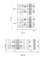
- FIG. 5A is a diagram showing FDM and TDM solutions for full CSI-RS port transmission
- FIG. 5B is a diagram showing FDM and TDM solutions for full CSI-RS port transmission
- FIG. 6 is a block diagram schematically showing a base station according to an embodiment of the present disclosure.
- FIG. 7 is a diagram showing operations of the base station mapping the CSI-RS ports to the resource blocks according to the first embodiment of the present disclosure
- FIG. 8 is a diagram showing the CSI-RS ports by cyclically shifted transmission according to the second embodiment of the present disclosure.
- FIG. 9 is a diagram showing a cyclic shifted transmission of split CSI-RS ports according to the third embodiment of the present disclosure.
- FIG. 10 is a block diagram showing user equipment (UE) according to a further embodiment of the present disclosure.
- FIG. 11 shows a flow chart of a method of mapping the CSI-RS ports to resource blocks according to the first embodiment of the present disclosure
- FIG. 12 shows a flow chart of a method of mapping the CSI-RS ports to resource blocks according to the second embodiment of the present disclosure.
- FIG. 13 shows a flow chart of a method of mapping the CSI-RS ports to resource blocks according to the third embodiment of the present disclosure.
- the FD-MIMO with 64 antenna units is taken as an example, but the present disclosure could also be used for other case such as the elevation beamforming.
- FIGS. 5A and 5B are diagrams showing FDM and TDM solutions for full CSI-RS port transmission.
- the CSI-RS ports are split in TDM or FDM manner, just as shown in FIGS. 5A and 5B .
- PRB # 1 and PRB # 2 are resource blocks distributed in frequency domain, and according to a straightforward way, 32 CSI-RS ports are mapped onto 32 REs on the PRB # 1 , and other 32 CSI-RS ports are mapped onto 32 REs on the PRB # 2 .
- two resource blocks are distributed in time domain, in which one is TTI # 1 , and another is TTI # 2 .
- TTI # 1 32 CSI-RS ports are mapped onto 32 REs on the PRB of TTI # 1
- other 32 CSI-RS ports are mapped onto 32 REs on the PRB of TTI # 2 .
- the TTI means transmission time interval.
- the CSI-RS ports configuration are not optimized based on UE requirements. Users with different mobility will be configured by full CSI-RS transmission in each period. That would somehow waste the CSI-RS resources largely.
- partial CSI-RS ports with dense periodicity are reasonable by considering that: 1) inaccurate CSI feedback can not support FD-MIMO well (full CSI-RS port transmission is not necessary), 2) delay tolerance is smaller due to fast variation of channels.
- full CSI-RS ports with sparse periodicity are reasonable by considering that: 1) accurate CSI feedback can support FD-MIMO very well, 2) delay tolerance is larger (channel in time domain is more flat), i.e., dense periodicity is not necessary. So the requirement of CSI-RS ports transmission between the high mobility user and the low mobility user is totally different.
- FIG. 6 is a block diagram schematically showing a base station (eNB) 600 according to an embodiment of the present disclosure.
- the base station 600 has a function of mapping CSI-RS ports to resource elements on the resource blocks, which configure different CSI-RS ports with different periodicity based on UE requirements (e.g. mobility) to reduce CSI-RS overhead.
- Low speed/mobility users can see all the CSI-RS ports but with relatively long periodicity.
- For high speed/mobility users only partial CSI-RS ports with dense periodicity will be configured. So different users would have different configurations on CSI-RS ports, and different CSI-RS groups have different periodicity.
- the blocks indicated with different slash lines represent different CSI-RS ports.
- the eNB 600 comprising a mapping unit 601 which is configured to map a first group of CSI-RS ports to the resource blocks in a first transmission period, and map a second group of CSI-RS ports to the resource blocks in a second transmission period, in which the number of the CSI-RS ports in the first group is mare than that in the second group, and the length of the first transmission period is longer than that of the second transmission period.
- a mapping unit 601 which is configured to map a first group of CSI-RS ports to the resource blocks in a first transmission period, and map a second group of CSI-RS ports to the resource blocks in a second transmission period, in which the number of the CSI-RS ports in the first group is mare than that in the second group, and the length of the first transmission period is longer than that of the second transmission period.
- FIG. 7 is a diagram showing operations of the base station mapping the CSI-RS ports to the resource blocks according to the first embodiment of the present disclosure. Specifically, as shown in FIG. 7 , in a period T (referred to as a first transmission period), the mapping unit 601 maps a (first) group of CSI-RS ports 711 , 712 , 713 , 714 to the resource blocks, and in a period 2T (referred to as a second transmission period), the mapping unit 601 maps another (second) group of CSI-RS ports 711 to the resource blocks.
- T referred to as a first transmission period
- the mapping unit 601 maps another (second) group of CSI-RS ports 711 to the resource blocks.
- the CSI-RS ports 711 may comprise such as ports 0-15
- the CSI-RS ports 712 may comprise such as ports 16-31
- the CSI-RS ports 713 may comprise such as ports 32-47
- the CSI-RS ports 714 may comprise such as ports 48-63. It can be seen that the number of the CSI-RS ports in the first group ( 711 , 712 , 713 , 714 ) which is 64 is more than that (16) in the second group ( 711 ).
- one period T may for example include two TTIs.
- the same group of CSI-RS ports 711 are mapped to the resource blocks, i.e., the length of the transmission period of the CSI-RS ports 711 is T.
- the first group of CSI-RS ports 711 , 712 , 713 , 714 is used for users with low mobility
- the second group of CSI-RS ports 711 is used for users with high mobility
- the third group of CSI-RS ports 711 , 712 , or 711 , 712 , 713 is used for users with medium mobility.
- CSI-RS transmission pattern is necessary to be indicated to do rate matching of PDSCH.
- the pattern indication could be a manner of RRC, MAC CE or L1 signaling.
- RRC signaling one option is to send a CSI-RS pattern which would reflect the real CSI-RS number transmission, and another option is that the communication system sends all configured CSI-RS patterns used for different user equipments. User equipments will calculate the CSI-RS ports really transmitted based on all these patterns.
- a Pc (power) pattern of CSI-RS ports should be indicated if power boosting is used for the TTI sending partial ports. Power boosting could be used to improve the SINR if only partial CSI-RS ports are transmitted. For example, as shown in FIG. 7 , only 16 CSI-RS ports 711 are transmitted in second period (2T) or fourth period (4T) so that the power boosting could be carried out to improve the signal quality. But when and how the power boosting (Pc in CSI-RS-ConfigNZP-r11) is used should be indicated as well in terms of RRC, MAC, L1 signaling. We can add one field named Pc_pattern in CSI-RS-ConfigNZP-r11 message to indicate the power boosting variation pattern.
- the eNB 600 may comprise a transmitting unit 602 which is configured to transmit a message indicating the configuration of the CSI-RS ports on the resource blocks and/or a message indicating power boosting variation pattern when partial CSI-RS ports are transmitted to user equipments, in which the message are configured by RRC signaling, MAC signaling or L1 signaling.
- the resource blocks mapping the first group, second group, and third group of CSI-RS ports may be periodically transmitted from the base station to the user equipments by periodically shifting respective groups of CSI-RS ports.
- the eNB 600 may further include a CPU (Central Processing Unit) 610 for executing related programs to process various data and control the operations of respective units in the eNB 600 , a ROM (Read Only Memory) 613 for storing various programs required for performing various process and control by the CPU 610 , a RAM (Random Access Memory) 615 for storing intermediate data temporarily produced in the procedure of process and control by the CPU 610 , and/or a storage unit 617 for storing various programs, data and so on.
- the above mapping unit 601 , transmitting unit 602 , CPU 610 , ROM 613 , RAM 615 and/or storage unit 617 etc. may be interconnected via data and/or command bus 620 and transfer signals from one to another.
- mapping unit 601 and the transmitting unit 602 may also be implemented by one unit, and the functions of any or combination of the mapping unit 601 and the transmitting unit 602 may also be implemented by functional software in combination with the CPU 610 , ROM 613 , RAM 615 and/or storage unit 617 etc.
- the average CSI-RS overhead could be largely reduced.
- the overhead problem may sill exist for partial users with full CSI-RS ports transmission, although the average overhead gets a large reduction. Therefore, in the second embodiment of the present disclosure, it is further proposed to reduce the CSI-RS ports for such kind of users by cyclically shifted transmission of the CSI-RS ports with reduced CSI-RS REs. For example, if totally 64 CSI-RS ports are necessary, only 40 CSI-RS ports are transmitted or only 40 REs are occupied in each PRB in each period, but all these 64 CSI-RS ports would share the 40 CSI-RS REs in a cyclic shifted manner.
- FIG. 8 is a diagram showing the CSI-RS ports by cyclically shifted transmission according to the second embodiment of the present disclosure.
- first period T the CSI-RS ports 1-40 (40 ports) are transmitted, and in second period 6T, the CSI-RS ports 17-56 (40 ports) are transmitted. Therefore, in each period such as T or 6T, totally 24 resource elements mapping the CSI-RS ports are saved.
- the cyclically shifted offset of the CSI-RS ports could be any of 8, 16, 24, 32, 40, 48, or 56 ports, and it may be configured by the base station using RRC signaling.
- one period T may for example include one TTI.
- the mapping unit 601 of the base station is configured to map a first group of CSI-RS ports (for example, CSI-RS ports 1-40) onto the resource blocks in a first transmission period (for example, T), and map a second group of CSI-RS ports (for example, CSI-RS ports 17-56) onto the resource blocks in a second transmission period (for example, 6T), in which the second group of CSI-RS ports (for example, CSI-RS ports 17-56) are formed by cyclically shifting the first group of CSI-RS ports (for example, CSI-RS ports 1-40) by a shifted offset of 16 CSI-RS ports, among the plurality of CSI-RS ports (for example, 64 CSI-RS ports).
- the cyclically shifted offset (8, 16, 24, 32, 40, 48, or 56) of the CSI-RS ports do not limit the scope of the present disclosure, it may be any other number such as 1, 2, 4, etc.
- FIG. 9 is a diagram showing a cyclic shifted transmission of split CSI-RS ports according to the third embodiment of the present disclosure.
- the split manner is TDM.
- first TTI (TTI # 1 ) sends first half of the CSI-ports 1-32
- second TTI (TTI # 2 ) sends second half of the CSI-RS ports 33-64.
- the problem of such solution is the potential larger interference difference. For example, as shown in FIG.
- the transmission relationship between two CSI-RS groups could be cyclically shifted changed. For example, in the second period, a second half of the CSI-RS ports 33-64 could be transmitted firstly in TTI # 6 , and a first half of the CSI-RS ports 1-32 could be transmitted secondly in TTI # 7 . In the third period, the above transmission is repeated.
- the mapping unit 601 of the base station 600 is configured to map a first group of CSI-RS ports (ports 1-32) onto the resource blocks in first half (TTI# 1 ) of a first transmission period, a second group of CSI-RS ports (ports 33-64) onto the resource blocks in second half (TTI# 2 ) of the first transmission period, and to map the second group of CSI-RS ports (ports 33-64) onto the resource blocks in first half (TTI# 6 ) of a second transmission period, and the first group of CSI-RS ports (ports 1-32) onto the resource blocks in second half (TTI# 7 ) of the second transmission period, in which the second group of CSI-RS ports (ports 33-64) are formed by cyclically shifting the first group of CSI-RS ports respectively.
- FIG. 9( c ) shows a CSI-RS port selection window sliding based on a certain rule, in which the shifted offset is 32 CSI-RS ports.
- FIG. 9( d ) shows another CSI-RS port selection window sliding based on a certain rule, in which the shifted offset is 16 CSI-RS ports.
- the above shifted offset of the CSI-RS ports does not limit the scope of the present disclosure, and it can be any of 8, 16, 24, 32, 40, 48, or 56 CSI-RS ports or any other value.
- the cyclically shifted offset may be configured by the base station using RRC signaling.
- the interference between split CSI-RS ports in different TTIs is averaged and the performance is improved.
- FIG. 10 is a block diagram showing user equipment (UE) according to a further embodiment of the present disclosure.
- the UE 1000 comprises a receiving unit 1001 which is configured to receive resource blocks from a base station, in which a first group of CSI-RS ports are mapped onto the resource blocks in a first transmission period, and a second group of CSI-RS ports are mapped onto the resource blocks in a second transmission period, wherein the number of the CSI-RS ports in the first group is more than that in the second group, and the first transmission period is longer than the second transmission period.
- a third group of CSI-RS ports are mapped onto the resource blocks in a third transmission period, wherein the number of the CSI-RS ports in the third group is less than that in the first group and more than that in the second group, and the third transmission period is shorter than the first transmission period and longer than the second transmission period.
- the first group of CSI-RS ports includes relatively more CSI-RS ports (for example 64 ports), the second group of CSI-RS ports includes relatively less CSI-RS ports (for example 16 ports), and the third group of CSI-RS ports includes another part of full ports but its number is between the number of first group of CSI-RS ports and the number of second group of CSI-RS ports, for example 32 or 48 ports.
- the first group of CSI-RS ports is used for user equipments with low mobility
- the second group of CSI-RS ports is used for user equipments with high mobility
- the third group of CSI-RS ports is used for user equipments with medium mobility.
- a message indicating the configuration of the CSI-RS ports on the resource blocks and/or a message indicating a power boosting variation pattern when partial CSI-RS ports are transmitted is configured by a base station using RRC signaling, MAC signaling or L1 signaling.
- the receiving unit 1001 is configured to receive resource blocks from a base station, in which a first group of CSI-RS ports is mapped onto the resource blocks in a first transmission period, and a second group of CSI-RS ports is mapped onto the resource blocks in a second transmission period, wherein the second group of CSI-RS ports is formed by cyclically shifting the first group of CSI-RS ports.
- the cyclically shifted offset of the CSI-RS ports may be any of 8, 16, 24, 32, 40, 48, or 56 ports.
- the cyclically shifted offset may be configured by a base station using RRC signaling.
- the receiving unit 1001 is configured to receive resource blocks from a base station, in which a first group of CSI-RS ports is mapped onto the resource blocks in first half of a first transmission period, a second group of CSI-RS ports is mapped onto the resource blocks in second half of the first transmission period, and the second group of CSI-RS ports is mapped onto the resource blocks in first half of a second transmission period, and the first group of CSI-RS ports is mapped onto the resource blocks in second half of the second transmission period, wherein the second group of CSI-RS ports is formed by cyclically shifting the first group of CSI-RS ports.
- the cyclically shifted offset of the CSI-RS ports may be any of 8, 16, 24, 32, 40, 48, or 56 ports.
- the cyclically shifted offset may be configured by a base station using RRC signaling.
- the UE 1000 may further include a CPU (Central Processing Unit) 1010 for executing related programs to process various data and control operations of respective units in the UE 1000 , a ROM (Read Only Memory) 1013 for storing various programs required for performing various process and control by the CPU 1010 , a RAM (Random Access Memory) 1015 for storing intermediate data temporarily produced in the procedure of process and control by the CPU 1010 , and/or a storage unit 1017 for storing various programs, data and so on.
- the above receiving unit 1001 , CPU 1010 , ROM 1013 , RAM 1015 and/or storage unit 1017 etc. may be interconnected via data and/or command bus 1020 and transfer signals from one to another.
- Respective units as described above do not limit the scope of the present disclosure. According to an embodiment of the present disclosure, the functions of any or combination of the above receiving unit 1001 may also be implemented by functional software in combination with the above CPU 1010 , ROM 1013 , RAM 1015 and/or storage unit 1017 etc.
- the average overhead of CSI-RS transmission is largely reduced, and the interference between split CSI-RS ports in different TTIs is averaged and the performance is improved.
- FIG. 11 shows a flow chart of a method of mapping the CSI-RS ports to resource blocks according to the first embodiment of the present disclosure.
- the method begins at step S 1101 .
- a first group of CSI-RS ports is mapped onto the resource blocks in a first transmission period.
- a second group of CSI-RS ports is mapped onto the resource blocks in a second transmission period, wherein the number of the CSI-RS ports in the first group is more than that in the second group, and the first transmission period is longer than the second transmission period.
- the steps S 1101 and S 1102 may be performed by the mapping unit 601 of the base station 600 of the present disclosure.
- the method comprising a further step of mapping a third group of CSI-RS ports onto the resource blocks in a third transmission period, wherein the number of the CSI-RS ports in the third group is less than that in the first group and more than that in the second group, and the third transmission period is shorter than the first transmission period and longer than the second transmission period.
- the first group of CSI-RS ports includes relatively more CSI-RS ports (for example 64 ports or more or less), the second group of CSI-RS ports includes relatively less CSI-RS ports (for example 16 ports), and the third group of CSI-RS ports includes another part of full ports but its number is between the number of first group of CSI-RS ports and the number of second group of CSI-RS ports, for example 32 or 48 ports.
- the first group of CSI-RS ports is used for user equipments with low mobility
- the second group of CSI-RS ports is used for user equipments with high mobility
- the third group of CSI-RS ports is used for user equipments with medium mobility.
- a message indicating the configuration of the CSI-RS ports on the resource blocks and/or a message indicating a power boosting variation pattern is configured by RRC signaling, MAC signaling or L1 signaling.
- FIG. 12 shows a flow chart of a method of mapping the CSI-RS ports to resource blocks according to the second embodiment of the present disclosure.
- the method begins at step S 1201 .
- a first group of CSI-RS ports is mapped onto the resource blocks in a first transmission period.
- a second group of CSI-RS ports is mapped onto the resource blocks in a second transmission period, wherein the second group of CSI-RS ports is formed by cyclically shifting the first group of CSI-RS ports.
- the steps S 1201 and S 1202 may be performed by the mapping unit 601 of the base station 600 of the present disclosure.
- the cyclically shifted offset of the CSI-RS ports may be 8, 16, 24, 32, 40, 48, or 56 ports.
- the cyclically shifted offset may be configured by a base station using RRC signaling.
- FIG. 13 shows a flow chart of a method of mapping the CSI-RS ports to resource blocks according to the third embodiment of the present disclosure. As shown in FIG. 13 , the method begins at step S 1301 . At the step S 1301 , a first group of CSI-RS ports is mapped onto the resource blocks in first half of a first transmission period, a second group of CSI-RS ports is mapped onto the resource blocks in second half of the first transmission period.
- the second group of CSI-RS ports is mapped onto the resource blocks in first half of a second transmission period, and the first group of CSI-RS ports is mapped onto the resource blocks in second half of the second transmission period, wherein the second group of CSI-RS ports is formed by cyclically shifting the first group of CSI-RS ports.
- the steps S 1301 and S 1302 may be performed by the mapping unit 601 of the base station 600 of the present disclosure.
- the cyclically shifted offset of the CSI-RS ports may be any of 8, 16, 24, 32, 40, 48, or 56 ports.
- the cyclically shifted offset may be configured by a base station using RRC signaling.
- the embodiments of the present disclosure may be implemented by hardware, software and firmware or in a combination thereof, and the way of implementation does not limit the scope of the present disclosure.
- connection relationships between the respective functional elements (units) in the embodiments of the present disclosure do not limit the scope of the present disclosure, in which one or multiple functional element(s) or unit(s) may contain or be connected to any other functional elements.
Abstract
The present disclosure provides a communication method that a base station configures different CSI-RS ports with different periodicity based on UE requirement (e.g. mobility) to reduce CSI-RS overhead. And another method is to transmit partial CSI-RS ports in a cyclic shifted manner to further reduce the overhead. In addition, cyclic shifted transmission of split CSI-RS port groups are proposed to reduce the potential big difference of interference onto different CSI-RS port groups.
Description
The present disclosure relates to a method of mapping CSI-RS (channel state information-reference signal) ports to resource blocks in FD-MIMO (full dimension multiple-input multiple-output) communication system in LTE (Long Term Evolution).
Beamforming which is a kind of multiple antenna technology has been already adopted in early Long Term Evolution (LTE) standard release to enhance the coverage throughput. With respect to this technology, people were mainly focusing on azimuth domain so far. For example, how to form a horizontal beam using a certain weighting vector has been studied. In elevation domain, a fixed downtilt instead of a certain dynamic beam is supported in current LTE system.
With the increase of requirement on the elevation domain beamforming, 3D beamforming seems more and more important especially in urban area, in which users locate on different floors of the building. Using traditional horizontal beamforming technology can not serve these users very well, so the elevation domain and the horizontal domain both need to consider beamfoming, which is actually the 3D beamforming.
As the 3GPP TR 37.840 indicates, there could be different AAS deployment scenarios, such as Wide Area AAS (Macro AAS), Medium Range AAS (Micro AAS), and Local Area coverage AAS (Pico AAS), depending on the level of minimum coupling loss, the location of eNB (base station) antennas, etc. The range of each AAS scenario could be benefited from the 3D beamforming.
In 3GPP Release12, potentially two study items related with 3D beamforming would be discussed: one is the elevation beamforming and another is the FD-MIMO. The former assumes maximum 8 antenna ports and the latter could support {16, 32, 64} or even larger antenna ports. The antenna port is kind of logical signals which may be transmitted by several antenna units (physical antennas).
The present disclosure is made in consideration of the above aspects.
According to one aspect of the present disclosure, there is provided a communication method of mapping CSI-RS ports onto resource blocks, comprising steps of: mapping a first group of CSI-RS ports onto the resource blocks in a first transmission period; and mapping a second group of CSI-RS ports onto the resource blocks in a second transmission period, wherein the number of the CSI-RS ports in the first group is more than that in the second group, and the first transmission period is longer than the second transmission period.
In the present disclosure, the communication method further comprising steps of mapping a third group of CSI-RS ports onto the resource blocks in a third transmission period, wherein the number of the CSI-RS ports in the third group is less than that in the first group and more than that in the second group, and the third transmission period is shorter than the first transmission period and longer than the second transmission period.
In the present disclosure, the first group of CSI-RS ports includes relatively more CSI-RS ports (for example 64 ports), the second group of CSI-RS ports includes relatively less CSI-RS ports (for example 16 ports), and the third group of CSI-RS ports includes another part of full ports but its number is between the number of first group of CSI-RS ports and the number of second group of CSI-RS ports, for example 32 or 48 ports.
In the present disclosure, the first group of CSI-RS ports is used for user equipments with low mobility, the second group of CSI-RS ports is used for user equipments with high mobility, and the third group of CSI-RS ports is used for user equipments with medium mobility.
In the present disclosure, a message indicating the configuration of the CSI-RS ports on the resource blocks and/or a message indicating a power boosting variation pattern is configured by RRC signaling, MAC signaling or L1 signaling.
According to another aspect of the present disclosure, there is provided a communication method of mapping CSI-RS ports onto resource blocks, comprising steps of: mapping a first group of CSI-RS ports onto the resource blocks in a first transmission period; and mapping a second group of CSI-RS ports onto the resource blocks in a second transmission period, wherein the second group of CSI-RS ports are formed by cyclically shifting the first group of CSI-RS ports.
In the present disclosure, the cyclically shifted offset is configured by a base station using RRC signaling.
According to a further aspect of the present disclosure, there is provided a communication method of mapping CSI-RS ports onto resource blocks, comprising steps of mapping a first group of CSI-RS ports onto the resource blocks in first half of a first transmission period, a second group of CSI-RS ports onto the resource blocks in second half of the first transmission period; and mapping the second group of CSI-RS ports onto the resource blocks in first half of a second transmission period, and the first group of CSI-RS ports onto the resource blocks in second half of the second transmission period, wherein the second group of CSI-RS ports are formed by cyclically shifting the first group of CSI-RS ports.
In the present disclosure, the cyclically shifted offset is configured by a base station using RRC signaling.
According to a further aspect of the present disclosure, there is provided a base station for mapping CSI-RS ports onto resource blocks, comprising: a mapping unit configured to map a first group of CSI-RS ports onto the resource blocks in a first transmission period, and a second group of CSI-RS ports onto the resource blocks in a second transmission period, wherein the number of the CSI-RS ports in the first group is more than that in the second group, and the first transmission period is longer than the second transmission period.
In the present disclosure, the mapping unit is further configured to map a third group of CSI-RS ports onto the resource blocks in a third transmission period, wherein the number of the CSI-RS ports in the third group is less than that in the first group and more than that in the second group, and the third transmission period is shorter than the first transmission period and longer than the second transmission period.
In the present disclosure, the first group of CSI-RS ports includes relatively more CSI-RS ports (for example 64 ports), the second group of CSI-RS ports includes relatively less CSI-RS ports (for example 16 ports), and the third group of CSI-RS ports includes another part of full ports but its number is between the number of first group of CSI-RS ports and the number of second group of CSI-RS ports, for example 32 or 48 ports.
In the present disclosure, the first group of CSI-RS ports is used for user equipments with low mobility, the second group of CSI-RS ports is used for user equipments with high mobility, and the third group of CSI-RS ports is used for user equipments with medium mobility.
In the present disclosure, a message indicating the configuration of the CSI-RS ports on the resource blocks and/or a message indicating a power boosting variation pattern is configured by RRC signaling, MAC signaling or L1 signaling.
According to a further aspect of the present disclosure, there is provided a base station for mapping a plurality of CSI-RS ports on resource blocks, comprising: a mapping unit configured to map a first group of CSI-RS ports on the resource blocks in a first transmission period, and a second group of CSI-RS ports on the resource blocks in a second transmission period, wherein the second group of CSI-RS ports are formed by cyclically shifting the first group of CSI-RS ports among the plurality of CSI-RS ports.
In the present disclosure, the cyclically shifted offset is configured by RRC signaling.
According to a further aspect of the present disclosure, there is provided a base station for mapping CSI-RS ports onto resource blocks, comprising: a mapping unit configured to map a first group of CSI-RS ports onto the resource blocks in first half of a first transmission period, a second group of CSI-RS ports onto the resource blocks in second half of the first transmission period, and to map the second group of CSI-RS ports onto the resource blocks in first half of a second transmission period, and the first group of CSI-RS ports onto the resource blocks in second half of the second transmission period, wherein the second group of CSI-RS ports are formed by cyclically shifting the first group of CSI-RS ports.
In the present disclosure, the cyclically shifted offset is configured by RRC signaling.
According to a further aspect of the present disclosure, there is provided a user equipment comprising: a receiving unit configured to receive resource blocks from a base station, in which a first group of CSI-RS ports is mapped onto the resource blocks in a first transmission period, and a second group of CSI-RS ports is mapped onto the resource blocks in a second transmission period, wherein the number of the CSI-RS ports in the first group is more than that in the second group, and the first transmission period is longer than the second transmission period.
In the present disclosure, a third group of CSI-RS ports is mapped onto the resource blocks in a third transmission period, wherein the number of the CSI-RS ports in the third group is less than that in the first group and more than that in the second group, and the third transmission period is shorter than the first transmission period and longer than that of the second transmission period.
In the present disclosure, the first group of CSI-RS ports includes relatively more CSI-RS ports (for example 64 ports), the second group of CSI-RS ports includes relatively less CSI-RS ports (for example 16 ports), and the third group of CSI-RS ports includes another part of full ports but its number is between the number of first group of CSI-RS ports and the number of second group of CSI-RS ports, for example 32 or 48 ports.
In the present disclosure, the first group of CSI-RS ports is used for user equipments with low mobility, the second group of CSI-RS ports is used for user equipments with high mobility, and the third group of CSI-RS ports is used for user equipments with medium mobility.
In the present disclosure, a message indicating the configuration of the CSI-RS ports on the resource blocks and/or a message indicating power boosting variation pattern is configured by a base station using RRC signaling, MAC signaling or L1 signaling.
According to a further aspect of the present disclosure, there is provided a user equipment comprising: a receiving unit configured to receive resource blocks from a base station, in which a first group of CSI-RS ports is mapped onto the resource blocks in a first transmission period, and a second group of CSI-RS ports is mapped onto the resource blocks in a second transmission period, wherein the second group of CSI-RS ports is formed by cyclically shifting the first group of CSI-RS ports.
In the present disclosure, the cyclically shifted offset is configured by a base station using RRC signaling.
According to a further aspect of the present disclosure, there is provided a user equipment comprising: a receiving unit configured to receive resource blocks from a base station, in which a first group of CSI-RS ports is mapped onto the resource blocks in first half of a first transmission period, a second group of CSI-RS ports is mapped onto the resource blocks in second half of the first transmission period, and the second group of CSI-RS ports is mapped onto the resource blocks in first half of a second transmission period, and the first group of CSI-RS ports is mapped onto the resource blocks in second half of the second transmission period, wherein the second group of CSI-RS ports is formed by cyclically shifting the first group of CSI-RS ports.
In the present disclosure, the cyclically shifted offset is configured by a base station using RRC signaling.
The communication method, base station, and user equipment of the present disclosure could realize advantages that the average overhead of CSI-RS transmission is largely reduced, and the interference between split CSI-RS ports in different TTIs is averaged and the performance is improved.
These and/or other aspects and advantages of the present disclosure will become more clear and easier to be understood in detailed description of embodiments of the present disclosure below in conjunction with attached drawings, in which:
In the following detailed description, reference is made to the accompanying drawings, which form a part of the present disclosure. In the drawings, similar symbols typically indicate similar components, unless the context dictates otherwise. It will be readily understood that aspects of the present disclosure can be arranged, substituted, combined, and designed in a wide variety of different configurations, all of which are explicitly contemplated and make a part of the present disclosure.
In this specification, it is mainly focused on the macro AAS scenario, but any other scenario mentioned above could also be feasible case. In this specification, the FD-MIMO with 64 antenna units is taken as an example, but the present disclosure could also be used for other case such as the elevation beamforming.
The present disclosure will be described below in conjunction with the drawings.
Even though straightforward solution could solve the problem that 40 REs are not enough, some further enhancements are probably necessary. At least it can be seen that the overhead is still very large. For example, CSI-RS overhead could be 8 times of that in Rel.10 if we assume 64 CSI-RS ports are split into 2 consecutive PRBs, 5 ms periodicity, and PDSCH RE=11 symbols*12 sub-carriers.
In straightforward solutions, it can also be seen that the CSI-RS ports configuration are not optimized based on UE requirements. Users with different mobility will be configured by full CSI-RS transmission in each period. That would somehow waste the CSI-RS resources largely. Actually based on some analysis, for high mobility user, partial CSI-RS ports with dense periodicity are reasonable by considering that: 1) inaccurate CSI feedback can not support FD-MIMO well (full CSI-RS port transmission is not necessary), 2) delay tolerance is smaller due to fast variation of channels. Instead, for low mobility users, full CSI-RS ports with sparse periodicity are reasonable by considering that: 1) accurate CSI feedback can support FD-MIMO very well, 2) delay tolerance is larger (channel in time domain is more flat), i.e., dense periodicity is not necessary. So the requirement of CSI-RS ports transmission between the high mobility user and the low mobility user is totally different.
Therefore, according to an embodiment of the present disclosure, it is proposed to configure different CSI-RS ports with different periodicity based on UE requirements (e.g. mobility) to reduce CSI-RS overhead.
The eNB 600 comprising a mapping unit 601 which is configured to map a first group of CSI-RS ports to the resource blocks in a first transmission period, and map a second group of CSI-RS ports to the resource blocks in a second transmission period, in which the number of the CSI-RS ports in the first group is mare than that in the second group, and the length of the first transmission period is longer than that of the second transmission period.
According to the embodiment, as shown in FIG. 7 , in each of the periods T, 2T, 3T, 4T, 5T, 6T, 7T, . . . the same group of CSI-RS ports 711 are mapped to the resource blocks, i.e., the length of the transmission period of the CSI-RS ports 711 is T. On the other hand, in a period 7T, the first group of CSI- RS ports 711,712, 713, 714 are mapped to the resource blocks, i.e., the length of the transmission period of the CSI- RS ports 711,712, 713, 714 is 7T−T=6T. It can be seen that the length (6T) of the transmission period of the first group of CSI- RS ports 711,712, 713, 714 is longer than that (T) of the transmission period of the second group of CSI-RS ports 711.
According to another embodiment, as shown in FIG. 7 , the mapping unit 601 may further map a third group of CSI-RS ports (a group of CSI- RS ports 711, 712, or a group of CSI- RS ports 711, 712, 713) to the resource blocks in a (third) transmission period 3T or 5T, and it can be seen that the number (32 or 48) of the CSI-RS ports in the third group is less than that (64) in the first group and more than that (16) in the second group, and the length (5T−3T=2T or 9T−5T=4T) of the third transmission period is shorter than that (6T) of the first transmission period and longer than that (T) of the second transmission period.
According to another embodiment, the first group of CSI- RS ports 711, 712, 713, 714 is used for users with low mobility, the second group of CSI-RS ports 711 is used for users with high mobility, and the third group of CSI- RS ports 711, 712, or 711, 712, 713 is used for users with medium mobility.
For this embodiment, we also need to consider two things: for all user equipments, real CSI-RS transmission pattern is necessary to be indicated to do rate matching of PDSCH. The pattern indication could be a manner of RRC, MAC CE or L1 signaling. For example, for RRC signaling, one option is to send a CSI-RS pattern which would reflect the real CSI-RS number transmission, and another option is that the communication system sends all configured CSI-RS patterns used for different user equipments. User equipments will calculate the CSI-RS ports really transmitted based on all these patterns.
Additionally, a Pc (power) pattern of CSI-RS ports should be indicated if power boosting is used for the TTI sending partial ports. Power boosting could be used to improve the SINR if only partial CSI-RS ports are transmitted. For example, as shown in FIG. 7 , only 16 CSI-RS ports 711 are transmitted in second period (2T) or fourth period (4T) so that the power boosting could be carried out to improve the signal quality. But when and how the power boosting (Pc in CSI-RS-ConfigNZP-r11) is used should be indicated as well in terms of RRC, MAC, L1 signaling. We can add one field named Pc_pattern in CSI-RS-ConfigNZP-r11 message to indicate the power boosting variation pattern.
Therefore, the eNB 600 may comprise a transmitting unit 602 which is configured to transmit a message indicating the configuration of the CSI-RS ports on the resource blocks and/or a message indicating power boosting variation pattern when partial CSI-RS ports are transmitted to user equipments, in which the message are configured by RRC signaling, MAC signaling or L1 signaling. According to the embodiment, the resource blocks mapping the first group, second group, and third group of CSI-RS ports may be periodically transmitted from the base station to the user equipments by periodically shifting respective groups of CSI-RS ports.
The eNB 600 according to the present disclosure may further include a CPU (Central Processing Unit) 610 for executing related programs to process various data and control the operations of respective units in the eNB 600, a ROM (Read Only Memory) 613 for storing various programs required for performing various process and control by the CPU 610, a RAM (Random Access Memory) 615 for storing intermediate data temporarily produced in the procedure of process and control by the CPU 610, and/or a storage unit 617 for storing various programs, data and so on. The above mapping unit 601, transmitting unit 602, CPU 610, ROM 613, RAM 615 and/or storage unit 617 etc. may be interconnected via data and/or command bus 620 and transfer signals from one to another.
Respective units as described above do not limit the scope of the present disclosure. According to an embodiment of the present disclosure, the functions of the mapping unit 601 and the transmitting unit 602 may also be implemented by one unit, and the functions of any or combination of the mapping unit 601 and the transmitting unit 602 may also be implemented by functional software in combination with the CPU 610, ROM 613, RAM 615 and/or storage unit 617 etc.
In the first embodiment of the present disclosure, the average CSI-RS overhead could be largely reduced.
In the above-stated straightforward solution, it can be seen that the overhead problem may sill exist for partial users with full CSI-RS ports transmission, although the average overhead gets a large reduction. Therefore, in the second embodiment of the present disclosure, it is further proposed to reduce the CSI-RS ports for such kind of users by cyclically shifted transmission of the CSI-RS ports with reduced CSI-RS REs. For example, if totally 64 CSI-RS ports are necessary, only 40 CSI-RS ports are transmitted or only 40 REs are occupied in each PRB in each period, but all these 64 CSI-RS ports would share the 40 CSI-RS REs in a cyclic shifted manner.
Therefore, according to the embodiment of the present disclosure, the mapping unit 601 of the base station is configured to map a first group of CSI-RS ports (for example, CSI-RS ports 1-40) onto the resource blocks in a first transmission period (for example, T), and map a second group of CSI-RS ports (for example, CSI-RS ports 17-56) onto the resource blocks in a second transmission period (for example, 6T), in which the second group of CSI-RS ports (for example, CSI-RS ports 17-56) are formed by cyclically shifting the first group of CSI-RS ports (for example, CSI-RS ports 1-40) by a shifted offset of 16 CSI-RS ports, among the plurality of CSI-RS ports (for example, 64 CSI-RS ports).
According to another embodiment, the cyclically shifted offset (8, 16, 24, 32, 40, 48, or 56) of the CSI-RS ports do not limit the scope of the present disclosure, it may be any other number such as 1, 2, 4, etc.
In the above second embodiment of the present disclosure, overhead of the CSI-RS ports transmission is much reduced.
In the above-stated straightforward solution, there is another issue that if TDM based solution is used, the interference between the split CSI-RS ports in different TTIs may be very large potentially. Therefore, in the third embodiment of the present disclosure, it is proposed to use cyclic shifted transmission for the split CSI-RS groups to somehow relax the potentially larger interference difference.
As shown in FIG. 9(b) , according to the embodiment of the present disclosure, the mapping unit 601 of the base station 600 is configured to map a first group of CSI-RS ports (ports 1-32) onto the resource blocks in first half (TTI#1) of a first transmission period, a second group of CSI-RS ports (ports 33-64) onto the resource blocks in second half (TTI#2) of the first transmission period, and to map the second group of CSI-RS ports (ports 33-64) onto the resource blocks in first half (TTI#6) of a second transmission period, and the first group of CSI-RS ports (ports 1-32) onto the resource blocks in second half (TTI#7) of the second transmission period, in which the second group of CSI-RS ports (ports 33-64) are formed by cyclically shifting the first group of CSI-RS ports respectively.
According to an embodiment of the present disclosure, the cyclically shifted offset may be configured by the base station using RRC signaling.
In the third embodiment of the present disclosure, the interference between split CSI-RS ports in different TTIs is averaged and the performance is improved.
In another embodiment, a third group of CSI-RS ports are mapped onto the resource blocks in a third transmission period, wherein the number of the CSI-RS ports in the third group is less than that in the first group and more than that in the second group, and the third transmission period is shorter than the first transmission period and longer than the second transmission period.
In another embodiment, the first group of CSI-RS ports includes relatively more CSI-RS ports (for example 64 ports), the second group of CSI-RS ports includes relatively less CSI-RS ports (for example 16 ports), and the third group of CSI-RS ports includes another part of full ports but its number is between the number of first group of CSI-RS ports and the number of second group of CSI-RS ports, for example 32 or 48 ports.
In another embodiment, the first group of CSI-RS ports is used for user equipments with low mobility, the second group of CSI-RS ports is used for user equipments with high mobility, and the third group of CSI-RS ports is used for user equipments with medium mobility.
In another embodiment, a message indicating the configuration of the CSI-RS ports on the resource blocks and/or a message indicating a power boosting variation pattern when partial CSI-RS ports are transmitted is configured by a base station using RRC signaling, MAC signaling or L1 signaling.
In another embodiment of the present disclosure, the receiving unit 1001 is configured to receive resource blocks from a base station, in which a first group of CSI-RS ports is mapped onto the resource blocks in a first transmission period, and a second group of CSI-RS ports is mapped onto the resource blocks in a second transmission period, wherein the second group of CSI-RS ports is formed by cyclically shifting the first group of CSI-RS ports.
In another embodiment, the cyclically shifted offset of the CSI-RS ports may be any of 8, 16, 24, 32, 40, 48, or 56 ports. In the embodiment, the cyclically shifted offset may be configured by a base station using RRC signaling.
In a further embodiment of the present disclosure, the receiving unit 1001 is configured to receive resource blocks from a base station, in which a first group of CSI-RS ports is mapped onto the resource blocks in first half of a first transmission period, a second group of CSI-RS ports is mapped onto the resource blocks in second half of the first transmission period, and the second group of CSI-RS ports is mapped onto the resource blocks in first half of a second transmission period, and the first group of CSI-RS ports is mapped onto the resource blocks in second half of the second transmission period, wherein the second group of CSI-RS ports is formed by cyclically shifting the first group of CSI-RS ports.
In another embodiment, the cyclically shifted offset of the CSI-RS ports may be any of 8, 16, 24, 32, 40, 48, or 56 ports. In the embodiment, the cyclically shifted offset may be configured by a base station using RRC signaling.
The UE 1000 according to the present disclosure may further include a CPU (Central Processing Unit) 1010 for executing related programs to process various data and control operations of respective units in the UE 1000, a ROM (Read Only Memory) 1013 for storing various programs required for performing various process and control by the CPU 1010, a RAM (Random Access Memory) 1015 for storing intermediate data temporarily produced in the procedure of process and control by the CPU 1010, and/or a storage unit 1017 for storing various programs, data and so on. The above receiving unit 1001, CPU 1010, ROM 1013, RAM 1015 and/or storage unit 1017 etc. may be interconnected via data and/or command bus 1020 and transfer signals from one to another.
Respective units as described above do not limit the scope of the present disclosure. According to an embodiment of the present disclosure, the functions of any or combination of the above receiving unit 1001 may also be implemented by functional software in combination with the above CPU 1010, ROM 1013, RAM 1015 and/or storage unit 1017 etc.
In the above embodiments of the present disclosure, the average overhead of CSI-RS transmission is largely reduced, and the interference between split CSI-RS ports in different TTIs is averaged and the performance is improved.
In the embodiment, the method comprising a further step of mapping a third group of CSI-RS ports onto the resource blocks in a third transmission period, wherein the number of the CSI-RS ports in the third group is less than that in the first group and more than that in the second group, and the third transmission period is shorter than the first transmission period and longer than the second transmission period.
In the embodiment, the first group of CSI-RS ports includes relatively more CSI-RS ports (for example 64 ports or more or less), the second group of CSI-RS ports includes relatively less CSI-RS ports (for example 16 ports), and the third group of CSI-RS ports includes another part of full ports but its number is between the number of first group of CSI-RS ports and the number of second group of CSI-RS ports, for example 32 or 48 ports.
In the embodiment, the first group of CSI-RS ports is used for user equipments with low mobility, the second group of CSI-RS ports is used for user equipments with high mobility, and the third group of CSI-RS ports is used for user equipments with medium mobility.
In the embodiment, a message indicating the configuration of the CSI-RS ports on the resource blocks and/or a message indicating a power boosting variation pattern is configured by RRC signaling, MAC signaling or L1 signaling.
In a further embodiment, the cyclically shifted offset of the CSI-RS ports may be 8, 16, 24, 32, 40, 48, or 56 ports. In a further embodiment, the cyclically shifted offset may be configured by a base station using RRC signaling.
In a further embodiment, the cyclically shifted offset of the CSI-RS ports may be any of 8, 16, 24, 32, 40, 48, or 56 ports. In a further embodiment, the cyclically shifted offset may be configured by a base station using RRC signaling.
The above embodiments of the present disclosure are only exemplary description, and their specific structures and operations do not limit the scope of the present disclosure. Those skilled in the art can recombine different parts and operations of the above respective embodiments to produce new implementations which equally accord with the concept of the present disclosure.
The embodiments of the present disclosure may be implemented by hardware, software and firmware or in a combination thereof, and the way of implementation does not limit the scope of the present disclosure.
The connection relationships between the respective functional elements (units) in the embodiments of the present disclosure do not limit the scope of the present disclosure, in which one or multiple functional element(s) or unit(s) may contain or be connected to any other functional elements.
Although several embodiments of the present disclosure have been shown and described in combination with attached drawings above, those skilled in the art would understand that variations and modifications which still fall into the scope of claims and their equivalents of the present disclosure can be made to these embodiments without departing from the principle and spirit of the present disclosure.
Claims (9)
1. A communication method of mapping channel state information-reference signal (CSI-RS) ports onto resource blocks, comprising:
mapping a first group of CSI-RS ports used for user equipments with low mobility onto the resource blocks in a first transmission period, wherein the first transmission period is a regularly-repeated cycle in which the first group of CSI-RS ports is mapped onto the resource blocks; and
mapping a second group of CSI-RS ports used for user equipments with high mobility onto the resource blocks in a second transmission period, wherein the second transmission period is a regularly-repeated cycle in which the second group of CSI-RS ports is mapped onto the resource blocks,
wherein the number of the CSI-RS ports in the first group is more than that in the second group, and the first transmission period is longer than the second transmission period.
2. A base station for mapping channel state information-reference signal (CSI-RS) ports onto resource blocks, comprising:
a processor, which, in operation, maps a first group of CSI-RS ports used for user equipments with low mobility onto the resource blocks in a first transmission period, and maps a second group of CSI-RS ports used for user equipments with high mobility onto the resource blocks in a second transmission period, wherein the first transmission period is a regularly-repeated cycle in which the first group of CSI-RS ports is mapped onto the resource blocks and the second transmission period is a regularly-repeated cycle in which the second group of CSI-RS ports is mapped onto the resource blocks,
wherein the number of the CSI-RS ports in the first group is more than that in the second group, and the first transmission period is longer than the second transmission period, and
a transmitter, which, in operation, transmits the CSI-RS ports mapped onto the resource blocks.
3. The base station of claim 2 , wherein the processor further maps a third group of CSI-RS ports used for user equipments with medium mobility onto the resource blocks in a third transmission period, wherein the number of the CSI-RS ports in the third group is less than that in the first group and more than that in the second group, and the third transmission period is shorter than the first transmission period and longer than the second transmission period.
4. The base station of claim 3 , wherein the first group of CSI-RS ports includes relatively more ports, the second group of CSI-RS ports includes relatively less ports, and the number of third group of CSI-RS ports is between the number of first group of CSI-RS ports and the number of second of CSI-RS ports.
5. The base station of claim 3 , wherein at least one of a message indicating configuration of the CSI-RS ports on the resource blocks and a message indicating power boosting variation pattern is configured by radio resource control (RRC) signaling, media access control (MAC) signaling, or layer 1 (L1) signaling.
6. A user equipment comprising:
a receiver, which, in operation, receives, from a base station, resource blocks, onto which a first group of channel state information-reference signal (CSI-RS) ports used for user equipments with low mobility is mapped in a first transmission period, and onto which a second group of CSI-RS ports used for user equipments with high mobility is mapped in a second transmission period, wherein the first transmission period is a regularly-repeated cycle in which the first group of CSI-RS ports is mapped onto the resource blocks and the second transmission period is a regularly-repeated cycle in which the second group of CSI-RS ports is mapped onto the resource blocks,
wherein the number of the CSI-RS ports in the first group is more than that in the second group, and the first transmission period is longer than the second transmission period, and
a processor, which, in operation, performs channel estimation using at least some of the CSI-RS ports mapped onto the resource blocks.
7. The user equipment of claim 6 , wherein a third group of CSI-RS ports used for user equipments with medium mobility is mapped onto the resource blocks in a third transmission period, wherein the number of the CSI-RS ports in the third group is less than that in the first group and more than that in the second group, and the third transmission period is shorter than the first transmission period and longer than that of the second transmission period.
8. The user equipment of claim 7 , wherein the first group of CSI-RS ports includes relatively more ports, the second group of CSI-RS ports includes relatively less ports, and the number of third group of CSI-RS ports is between the number of first group of CSI-RS ports and the number of second group of CSI-RS ports.
9. The user equipment of claim 7 , wherein at least one of a message indicating configuration of the CSI-RS ports on the resource blocks and a message indicating power boosting variation pattern is configured by a base station using radio resource control (RRC) signaling, media access control (MAC) signaling, or layer 1 (L1) signaling.
Applications Claiming Priority (1)
| Application Number | Priority Date | Filing Date | Title |
|---|---|---|---|
| PCT/CN2013/073939 WO2014166052A1 (en) | 2013-04-09 | 2013-04-09 | Method of mapping csi-rs ports to resource blocks, base station and user equipment |
Publications (2)
| Publication Number | Publication Date |
|---|---|
| US20160050153A1 US20160050153A1 (en) | 2016-02-18 |
| US9882816B2 true US9882816B2 (en) | 2018-01-30 |
Family
ID=51688830
Family Applications (1)
| Application Number | Title | Priority Date | Filing Date |
|---|---|---|---|
| US14/779,553 Active 2033-06-13 US9882816B2 (en) | 2013-04-09 | 2013-04-09 | Method of mapping CSI-RS ports to resource blocks, base station and user equipment |
Country Status (4)
| Country | Link |
|---|---|
| US (1) | US9882816B2 (en) |
| JP (1) | JP6219496B2 (en) |
| CN (1) | CN105075319B (en) |
| WO (1) | WO2014166052A1 (en) |
Cited By (2)
| Publication number | Priority date | Publication date | Assignee | Title |
|---|---|---|---|---|
| US11323230B2 (en) * | 2017-03-24 | 2022-05-03 | Telefonaktiebolaget Lm Ericsson (Publ) | Method and apparatus for channel state information acquisition in low latency wireless systems |
| US11343041B2 (en) | 2017-08-31 | 2022-05-24 | Samsung Electronics Co., Ltd | Method and device for supporting repetitive CSI-RS resource transmission in mobile communication system |
Families Citing this family (21)
| Publication number | Priority date | Publication date | Assignee | Title |
|---|---|---|---|---|
| CN109743148B (en) | 2012-12-31 | 2021-11-19 | 上海华为技术有限公司 | Reference signal configuration method, reference signal sending method and related equipment |
| WO2015089715A1 (en) * | 2013-12-16 | 2015-06-25 | 华为技术有限公司 | Pilot signal transmission method, base station, and user device |
| KR102280021B1 (en) * | 2014-09-11 | 2021-07-21 | 삼성전자주식회사 | Scheme for transceiving reference signal in wireless comunication system |
| US9999073B2 (en) | 2014-11-18 | 2018-06-12 | Telefonaktiebolaget Lm Ericsson (Publ) | Signaling adapted CSI-RS periodicities in active antenna systems |
| CN106411473B (en) | 2015-07-27 | 2019-07-19 | 电信科学技术研究院 | A kind of reference signal mapping method and device |
| CN105262574B (en) * | 2015-09-17 | 2018-12-18 | 北京北方烽火科技有限公司 | A kind of CSI-RS port mapping method and device |
| KR102486805B1 (en) | 2015-09-18 | 2023-01-11 | 삼성전자 주식회사 | Method and apparatus for transmitting and receiving feedback signals in a wireless communication system |
| US10764008B2 (en) | 2016-03-30 | 2020-09-01 | Nec Corporation | Methods and apparatuses for transmitting and receiving reference signals |
| JP7160165B2 (en) * | 2016-03-30 | 2022-10-25 | 日本電気株式会社 | Method performed by base station and UE, base station and UE |
| JP6969633B2 (en) * | 2016-03-30 | 2021-11-24 | 日本電気株式会社 | How it is performed by the base station and UE |
| WO2017166288A1 (en) * | 2016-04-01 | 2017-10-05 | Qualcomm Incorporated | Csi-rs design for larger number of antenna ports for efd-mimo |
| WO2017166303A1 (en) * | 2016-04-01 | 2017-10-05 | 华为技术有限公司 | Method and apparatus for transmitting channel state information reference signal |
| US11811688B2 (en) * | 2016-04-01 | 2023-11-07 | Telefonaktiebolaget Lm Ericsson (Publ) | Reduced density channel state information reference signal |
| KR20170123960A (en) * | 2016-04-29 | 2017-11-09 | 삼성전자주식회사 | Method and apparatus for reference signal configurations and transmission in mobile communication system using massive array antennas |
| CN107370582A (en) * | 2016-05-12 | 2017-11-21 | 株式会社Ntt都科摩 | reference signal sending method, detection method, base station and mobile station |
| US20180054281A1 (en) * | 2016-08-19 | 2018-02-22 | Futurewei Technologies, Inc. | Method to transmit channel state information reference signals in large mimo systems |
| EP3515137B1 (en) | 2016-10-09 | 2022-06-15 | Huawei Technologies Co., Ltd. | Signal resource configuration method, terminal and access network device |
| WO2018098802A1 (en) * | 2016-12-02 | 2018-06-07 | Qualcomm Incorporated | Transmitting channel state information reference signals in new radio |
| CN109391571B (en) * | 2017-08-11 | 2020-12-04 | 华为技术有限公司 | Phase noise estimation method and equipment |
| CN110022195B (en) * | 2018-01-09 | 2020-09-29 | 维沃移动通信有限公司 | Measurement method, measurement configuration method, terminal and network equipment |
| CN112585884B (en) | 2018-09-30 | 2022-06-14 | 华为技术有限公司 | Communication method, device, network equipment, terminal equipment and system |
Citations (5)
| Publication number | Priority date | Publication date | Assignee | Title |
|---|---|---|---|---|
| CN102437987A (en) | 2010-09-29 | 2012-05-02 | 中兴通讯股份有限公司 | Method and device for generating and mapping channel state information reference signal sequence |
| CN102754458A (en) | 2010-02-12 | 2012-10-24 | 捷讯研究有限公司 | Reference signal for a coordinated multi-point network implementation |
| US20120288022A1 (en) | 2011-05-09 | 2012-11-15 | Jiann-Ching Guey | Channel estimation for a very large-scale multiple-input multiple-output (mimo) system |
| US20130044707A1 (en) | 2011-08-15 | 2013-02-21 | Texas Instruments Incorporated | CONFIGURATION OF CSI-RS FOR CoMP FEEDBACK |
| US20130301467A1 (en) * | 2011-01-19 | 2013-11-14 | Lg Electronics Inc. | Method and apparatus for receiving signal in multi-node system |
Family Cites Families (2)
| Publication number | Priority date | Publication date | Assignee | Title |
|---|---|---|---|---|
| KR101619446B1 (en) * | 2008-12-02 | 2016-05-10 | 엘지전자 주식회사 | Reference signal transmission method for downlink multiple input multiple output system |
| US9673945B2 (en) * | 2011-02-18 | 2017-06-06 | Qualcomm Incorporated | Implicitly linking aperiodic channel state information (A-CSI) reports to CSI-reference signal (CSI-RS) resources |
-
2013
- 2013-04-09 US US14/779,553 patent/US9882816B2/en active Active
- 2013-04-09 WO PCT/CN2013/073939 patent/WO2014166052A1/en active Application Filing
- 2013-04-09 CN CN201380075105.7A patent/CN105075319B/en not_active Expired - Fee Related
- 2013-04-09 JP JP2016506741A patent/JP6219496B2/en not_active Expired - Fee Related
Patent Citations (10)
| Publication number | Priority date | Publication date | Assignee | Title |
|---|---|---|---|---|
| CN102754458A (en) | 2010-02-12 | 2012-10-24 | 捷讯研究有限公司 | Reference signal for a coordinated multi-point network implementation |
| US20130039203A1 (en) | 2010-02-12 | 2013-02-14 | Mo-Han Fong | Reference signal for a coordinated multi-point network implementation |
| CN102437987A (en) | 2010-09-29 | 2012-05-02 | 中兴通讯股份有限公司 | Method and device for generating and mapping channel state information reference signal sequence |
| US20120207199A1 (en) | 2010-09-29 | 2012-08-16 | Zte Corporation | Method and device for generating and mapping channel state information reference signal sequence |
| US20130044728A1 (en) | 2010-09-29 | 2013-02-21 | Zte Corporation | Method and device for generating and mapping channel state information reference signal sequence |
| US8571067B2 (en) | 2010-09-29 | 2013-10-29 | Zte Corporation | Method and device for generating and mapping channel state information reference signal sequence |
| US8774226B2 (en) | 2010-09-29 | 2014-07-08 | Zte Corporation | Method and device for generating and mapping channel state information reference signal sequence |
| US20130301467A1 (en) * | 2011-01-19 | 2013-11-14 | Lg Electronics Inc. | Method and apparatus for receiving signal in multi-node system |
| US20120288022A1 (en) | 2011-05-09 | 2012-11-15 | Jiann-Ching Guey | Channel estimation for a very large-scale multiple-input multiple-output (mimo) system |
| US20130044707A1 (en) | 2011-08-15 | 2013-02-21 | Texas Instruments Incorporated | CONFIGURATION OF CSI-RS FOR CoMP FEEDBACK |
Non-Patent Citations (2)
| Title |
|---|
| 3GPP TR 37.840 V12.0.0, "3rd Generation Partnership Project; Technical Specification Group Radio Access Network; Study of Radio Frequency (RF) and Electromagnetic Compatibility (EMC) requirements for Active Antenna Array System (AAS) base station (Release 12)," Mar. 2013, 84 pages. |
| International Search Report dated Jan. 23, 2014, for corresponding International Application No. PCT/CN2013/073939, 2 pages. |
Cited By (4)
| Publication number | Priority date | Publication date | Assignee | Title |
|---|---|---|---|---|
| US11323230B2 (en) * | 2017-03-24 | 2022-05-03 | Telefonaktiebolaget Lm Ericsson (Publ) | Method and apparatus for channel state information acquisition in low latency wireless systems |
| US11343041B2 (en) | 2017-08-31 | 2022-05-24 | Samsung Electronics Co., Ltd | Method and device for supporting repetitive CSI-RS resource transmission in mobile communication system |
| US11349617B2 (en) * | 2017-08-31 | 2022-05-31 | Samsung Electronics Co., Ltd | Method and device for supporting repetitive CSI-RS resource transmission in mobile communication system |
| US11411700B2 (en) | 2017-08-31 | 2022-08-09 | Samsung Electronics Co., Ltd | Method and device for supporting repetitive CSI-RS resource transmission in mobile communication system |
Also Published As
| Publication number | Publication date |
|---|---|
| CN105075319A (en) | 2015-11-18 |
| US20160050153A1 (en) | 2016-02-18 |
| CN105075319B (en) | 2018-12-14 |
| JP2016516371A (en) | 2016-06-02 |
| WO2014166052A1 (en) | 2014-10-16 |
| JP6219496B2 (en) | 2017-10-25 |
Similar Documents
| Publication | Publication Date | Title |
|---|---|---|
| US9882816B2 (en) | Method of mapping CSI-RS ports to resource blocks, base station and user equipment | |
| US10749585B2 (en) | Method and apparatus for beam management reference signals in wireless communication systems | |
| KR102175608B1 (en) | Configurable reference signals | |
| CN110546929B (en) | Method and apparatus for transmitting channel state information reference signal (CSI-RS) and computer-readable storage medium | |
| KR102306131B1 (en) | Method and apparatus for information reporting, and method and apparatus for information transmission | |
| US11438081B2 (en) | Signal transmission method, related apparatus, and system | |
| US20190356444A1 (en) | Method and apparatus for transmitting and receiving reference signal in wireless communication system | |
| CN105191164B (en) | Method for mapping CSI-RS port to antenna unit and base station | |
| CN110754130B (en) | Apparatus and method for scheduling object configuration | |
| JP2019521543A (en) | Sounding Reference Signal (SRS) Design for Cellular Time Division Duplex (TDD) Millimeter Wave Systems | |
| TWI681680B (en) | Method and device for acquiring and feeding back beam information | |
| CA3053235A1 (en) | Method for measuring and reporting channel state information in wireless communication system and device therefor | |
| CN109391391B (en) | Method and device for transmitting reference signal | |
| US10177938B2 (en) | Device and method for adaptive channel estimation | |
| Polese et al. | 3GPP NR: the standard for 5G cellular networks | |
| US20220295297A1 (en) | Methods and apparatuses for time-domain beam-sweeping | |
| CN110268638B (en) | Method and device used for multi-antenna transmission in user equipment and base station |
Legal Events
| Date | Code | Title | Description |
|---|---|---|---|
| AS | Assignment |
Owner name: PANASONIC INTELLECTUAL PROPERTY CORPORATION OF AME Free format text: ASSIGNMENT OF ASSIGNORS INTEREST;ASSIGNORS:XU, MING;HOSHINO, MASAYUKI;TAKEDA, KAZUKI;AND OTHERS;SIGNING DATES FROM 20150601 TO 20150615;REEL/FRAME:037162/0162 |
|
| STCF | Information on status: patent grant |
Free format text: PATENTED CASE |
|
| MAFP | Maintenance fee payment |
Free format text: PAYMENT OF MAINTENANCE FEE, 4TH YEAR, LARGE ENTITY (ORIGINAL EVENT CODE: M1551); ENTITY STATUS OF PATENT OWNER: LARGE ENTITY Year of fee payment: 4 |