US9879655B1 - Attachment apparatus for an aerial vehicle - Google Patents
Attachment apparatus for an aerial vehicle Download PDFInfo
- Publication number
- US9879655B1 US9879655B1 US14/587,279 US201414587279A US9879655B1 US 9879655 B1 US9879655 B1 US 9879655B1 US 201414587279 A US201414587279 A US 201414587279A US 9879655 B1 US9879655 B1 US 9879655B1
- Authority
- US
- United States
- Prior art keywords
- wing
- attachment
- fastener
- clamshell
- fuselage
- Prior art date
- Legal status (The legal status is an assumption and is not a legal conclusion. Google has not performed a legal analysis and makes no representation as to the accuracy of the status listed.)
- Expired - Fee Related, expires
Links
- 241000269799 Perca fluviatilis Species 0.000 claims description 17
- 238000004891 communication Methods 0.000 description 24
- 238000013500 data storage Methods 0.000 description 12
- 230000006870 function Effects 0.000 description 10
- 239000000463 material Substances 0.000 description 8
- 230000005540 biological transmission Effects 0.000 description 7
- 239000003381 stabilizer Substances 0.000 description 7
- 229920000049 Carbon (fiber) Polymers 0.000 description 4
- 239000004917 carbon fiber Substances 0.000 description 4
- 230000001413 cellular effect Effects 0.000 description 4
- 238000006243 chemical reaction Methods 0.000 description 4
- VNWKTOKETHGBQD-UHFFFAOYSA-N methane Chemical compound C VNWKTOKETHGBQD-UHFFFAOYSA-N 0.000 description 4
- 238000000034 method Methods 0.000 description 4
- 238000010248 power generation Methods 0.000 description 4
- 230000005611 electricity Effects 0.000 description 3
- 239000000446 fuel Substances 0.000 description 3
- 239000003562 lightweight material Substances 0.000 description 3
- 230000003287 optical effect Effects 0.000 description 3
- 239000000853 adhesive Substances 0.000 description 2
- 230000001070 adhesive effect Effects 0.000 description 2
- 230000006835 compression Effects 0.000 description 2
- 238000007906 compression Methods 0.000 description 2
- 239000004020 conductor Substances 0.000 description 2
- 238000010586 diagram Methods 0.000 description 2
- 230000009977 dual effect Effects 0.000 description 2
- 238000005259 measurement Methods 0.000 description 2
- 239000004215 Carbon black (E152) Substances 0.000 description 1
- 238000004026 adhesive bonding Methods 0.000 description 1
- 229910052782 aluminium Inorganic materials 0.000 description 1
- XAGFODPZIPBFFR-UHFFFAOYSA-N aluminium Chemical compound [Al] XAGFODPZIPBFFR-UHFFFAOYSA-N 0.000 description 1
- 230000002457 bidirectional effect Effects 0.000 description 1
- 150000001875 compounds Chemical class 0.000 description 1
- 230000008878 coupling Effects 0.000 description 1
- 238000010168 coupling process Methods 0.000 description 1
- 238000005859 coupling reaction Methods 0.000 description 1
- 238000005265 energy consumption Methods 0.000 description 1
- 239000000835 fiber Substances 0.000 description 1
- 239000012530 fluid Substances 0.000 description 1
- 239000011521 glass Substances 0.000 description 1
- 230000005484 gravity Effects 0.000 description 1
- 229930195733 hydrocarbon Natural products 0.000 description 1
- 150000002430 hydrocarbons Chemical class 0.000 description 1
- 230000001939 inductive effect Effects 0.000 description 1
- 230000003993 interaction Effects 0.000 description 1
- 230000007774 longterm Effects 0.000 description 1
- 229910052751 metal Inorganic materials 0.000 description 1
- 239000002184 metal Substances 0.000 description 1
- 230000000737 periodic effect Effects 0.000 description 1
- 229920000642 polymer Polymers 0.000 description 1
- 230000003014 reinforcing effect Effects 0.000 description 1
- 239000007787 solid Substances 0.000 description 1
Images


Classifications
-
- F—MECHANICAL ENGINEERING; LIGHTING; HEATING; WEAPONS; BLASTING
- F03—MACHINES OR ENGINES FOR LIQUIDS; WIND, SPRING, OR WEIGHT MOTORS; PRODUCING MECHANICAL POWER OR A REACTIVE PROPULSIVE THRUST, NOT OTHERWISE PROVIDED FOR
- F03D—WIND MOTORS
- F03D9/00—Adaptations of wind motors for special use; Combinations of wind motors with apparatus driven thereby; Wind motors specially adapted for installation in particular locations
- F03D9/30—Wind motors specially adapted for installation in particular locations
- F03D9/32—Wind motors specially adapted for installation in particular locations on moving objects, e.g. vehicles
-
- B—PERFORMING OPERATIONS; TRANSPORTING
- B64—AIRCRAFT; AVIATION; COSMONAUTICS
- B64C—AEROPLANES; HELICOPTERS
- B64C1/00—Fuselages; Constructional features common to fuselages, wings, stabilising surfaces or the like
- B64C1/26—Attaching the wing or tail units or stabilising surfaces
-
- B—PERFORMING OPERATIONS; TRANSPORTING
- B64—AIRCRAFT; AVIATION; COSMONAUTICS
- B64C—AEROPLANES; HELICOPTERS
- B64C39/00—Aircraft not otherwise provided for
- B64C39/02—Aircraft not otherwise provided for characterised by special use
- B64C39/022—Tethered aircraft
-
- B—PERFORMING OPERATIONS; TRANSPORTING
- B64—AIRCRAFT; AVIATION; COSMONAUTICS
- B64F—GROUND OR AIRCRAFT-CARRIER-DECK INSTALLATIONS SPECIALLY ADAPTED FOR USE IN CONNECTION WITH AIRCRAFT; DESIGNING, MANUFACTURING, ASSEMBLING, CLEANING, MAINTAINING OR REPAIRING AIRCRAFT, NOT OTHERWISE PROVIDED FOR; HANDLING, TRANSPORTING, TESTING OR INSPECTING AIRCRAFT COMPONENTS, NOT OTHERWISE PROVIDED FOR
- B64F3/00—Ground installations specially adapted for captive aircraft
- B64F3/02—Ground installations specially adapted for captive aircraft with means for supplying electricity to aircraft during flight
-
- F—MECHANICAL ENGINEERING; LIGHTING; HEATING; WEAPONS; BLASTING
- F03—MACHINES OR ENGINES FOR LIQUIDS; WIND, SPRING, OR WEIGHT MOTORS; PRODUCING MECHANICAL POWER OR A REACTIVE PROPULSIVE THRUST, NOT OTHERWISE PROVIDED FOR
- F03D—WIND MOTORS
- F03D1/00—Wind motors with rotation axis substantially parallel to the air flow entering the rotor
- F03D1/06—Rotors
- F03D1/065—Rotors characterised by their construction elements
- F03D1/0658—Arrangements for fixing wind-engaging parts to a hub
-
- F03D1/0666—
-
- F—MECHANICAL ENGINEERING; LIGHTING; HEATING; WEAPONS; BLASTING
- F03—MACHINES OR ENGINES FOR LIQUIDS; WIND, SPRING, OR WEIGHT MOTORS; PRODUCING MECHANICAL POWER OR A REACTIVE PROPULSIVE THRUST, NOT OTHERWISE PROVIDED FOR
- F03D—WIND MOTORS
- F03D7/00—Controlling wind motors
- F03D7/02—Controlling wind motors the wind motors having rotation axis substantially parallel to the air flow entering the rotor
- F03D7/026—Controlling wind motors the wind motors having rotation axis substantially parallel to the air flow entering the rotor for starting-up
-
- F03D9/002—
-
- F—MECHANICAL ENGINEERING; LIGHTING; HEATING; WEAPONS; BLASTING
- F03—MACHINES OR ENGINES FOR LIQUIDS; WIND, SPRING, OR WEIGHT MOTORS; PRODUCING MECHANICAL POWER OR A REACTIVE PROPULSIVE THRUST, NOT OTHERWISE PROVIDED FOR
- F03D—WIND MOTORS
- F03D9/00—Adaptations of wind motors for special use; Combinations of wind motors with apparatus driven thereby; Wind motors specially adapted for installation in particular locations
- F03D9/20—Wind motors characterised by the driven apparatus
- F03D9/25—Wind motors characterised by the driven apparatus the apparatus being an electrical generator
-
- F—MECHANICAL ENGINEERING; LIGHTING; HEATING; WEAPONS; BLASTING
- F05—INDEXING SCHEMES RELATING TO ENGINES OR PUMPS IN VARIOUS SUBCLASSES OF CLASSES F01-F04
- F05B—INDEXING SCHEME RELATING TO WIND, SPRING, WEIGHT, INERTIA OR LIKE MOTORS, TO MACHINES OR ENGINES FOR LIQUIDS COVERED BY SUBCLASSES F03B, F03D AND F03G
- F05B2240/00—Components
- F05B2240/90—Mounting on supporting structures or systems
- F05B2240/92—Mounting on supporting structures or systems on an airbourne structure
- F05B2240/921—Mounting on supporting structures or systems on an airbourne structure kept aloft due to aerodynamic effects
-
- Y—GENERAL TAGGING OF NEW TECHNOLOGICAL DEVELOPMENTS; GENERAL TAGGING OF CROSS-SECTIONAL TECHNOLOGIES SPANNING OVER SEVERAL SECTIONS OF THE IPC; TECHNICAL SUBJECTS COVERED BY FORMER USPC CROSS-REFERENCE ART COLLECTIONS [XRACs] AND DIGESTS
- Y02—TECHNOLOGIES OR APPLICATIONS FOR MITIGATION OR ADAPTATION AGAINST CLIMATE CHANGE
- Y02E—REDUCTION OF GREENHOUSE GAS [GHG] EMISSIONS, RELATED TO ENERGY GENERATION, TRANSMISSION OR DISTRIBUTION
- Y02E10/00—Energy generation through renewable energy sources
- Y02E10/70—Wind energy
- Y02E10/72—Wind turbines with rotation axis in wind direction
-
- Y—GENERAL TAGGING OF NEW TECHNOLOGICAL DEVELOPMENTS; GENERAL TAGGING OF CROSS-SECTIONAL TECHNOLOGIES SPANNING OVER SEVERAL SECTIONS OF THE IPC; TECHNICAL SUBJECTS COVERED BY FORMER USPC CROSS-REFERENCE ART COLLECTIONS [XRACs] AND DIGESTS
- Y02—TECHNOLOGIES OR APPLICATIONS FOR MITIGATION OR ADAPTATION AGAINST CLIMATE CHANGE
- Y02E—REDUCTION OF GREENHOUSE GAS [GHG] EMISSIONS, RELATED TO ENERGY GENERATION, TRANSMISSION OR DISTRIBUTION
- Y02E10/00—Energy generation through renewable energy sources
- Y02E10/70—Wind energy
- Y02E10/728—Onshore wind turbines
Definitions
- Aerial vehicles may be composed of multiple separate components which are attached to each other via various attachment means.
- an attachment means may be a structure that is robust and lightweight in order to allow the aerial vehicle to expend less energy during flight.
- an apparatus in one example, includes a top clamshell having a first contoured surface that is configured to capture at least a portion of a top surface of a wing of an airborne wind turbine (AWT).
- the apparatus further includes a bottom clamshell having a second contoured surface that is configured to capture at least a portion of a bottom surface of the wing.
- the first contoured surface and the second contoured surface are configured to restrain the wing between the top clamshell and the bottom clamshell.
- the top clamshell is configured to be coupled to the fuselage attachment via a fastener at an aft end of the attachment apparatus.
- an airborne wind turbine in another example, includes a ground station, a tether, and an aerial vehicle.
- the aerial vehicle is configured to be coupled to the ground station via the tether, and the aerial vehicle includes an attachment apparatus.
- the attachment apparatus further includes a top clamshell having a first contoured surface that is configured to capture at least a portion of a top surface of a wing of the aerial vehicle.
- the attachment apparatus also includes a bottom clamshell having a second contoured surface that is configured to capture at least a portion of a bottom surface of the wing.
- the first contoured surface and the second contoured surface are configured to restrain the wing between the top clamshell and the bottom clamshell.
- the top clamshell is configured to be coupled to the fuselage attachment via a fastener at an aft end of the attachment apparatus.
- an apparatus in yet another example, includes a top clamshell having a first contoured surface that captures at least a portion of a top surface of a wing of an airborne wind turbine (AWT).
- the first contoured surface is adhesively coupled to the top surface of the wing.
- the apparatus further includes a bottom clamshell having a second contoured surface that captures at least a portion of a bottom surface of the wing.
- the second contoured surface is adhesively coupled to the bottom surface of the wing.
- the apparatus further includes a fuselage attachment adhesively coupled to a fuselage tube of the AWT by inserting a portion of the fuselage attachment into the fuselage tube.
- the fuselage attachment supports a portion of a surface of the bottom clamshell between a leading edge and a trailing edge of the wing.
- the fuselage attachment further includes a first hardpoint rib located at a forward end of the fuselage attachment.
- the first hardpoint rib receives a first fastener and is coupled to a balance boom of the AWT.
- the fuselage attachment further includes a second hardpoint rib located at an aft end of the fuselage attachment.
- the second hardpoint rib receives a second fastener and is coupled to a perch peg of the AWT.
- the fuselage attachment further includes a third hardpoint rib located between the first and second hardpoint ribs.
- the third hardpoint rib is coupled to the perch peg of the AWT.
- the top clamshell is coupled to the fuselage attachment via the first fastener and the second fastener.
- FIG. 1 depicts an airborne wind turbine.
- FIG. 2 is a simplified block diagram illustrating example components of the airborne wind turbine.
- FIG. 3 is an exploded view of an attachment apparatus for an aerial vehicle.
- FIG. 4A is a side exploded view of an attachment apparatus for an aerial vehicle.
- FIG. 4B is a cross section of example contoured surfaces.
- FIG. 4C is a cross section of other example contoured surfaces.
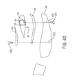
- FIG. 4D is a side exploded view of another attachment apparatus for an aerial vehicle.
- FIG. 5 is an assembled view of an attachment apparatus for an aerial vehicle.
- FIG. 6A is a side cross section of an attachment apparatus for an aerial vehicle.
- FIG. 6B is a side cross section of another attachment apparatus for an aerial vehicle.
- An airborne wind turbine may include an aerial vehicle that flies in a substantially circular path to convert kinetic wind energy to electrical energy.
- the aerial vehicle may include a wing that resembles a portion of a conventional wind turbine blade and is tethered to a ground station. Once deployed into the air, the wing can be controlled to react to wind similarly to a conventional wind turbine blade in that the wing may make periodic revolutions around a circular path that is substantially perpendicular to a direction of an apparent wind (ie. cross-wind flight).
- the wing may have one or more dual purpose motor/generators mounted on the wing such that when the wing repeatedly flies along the circular path, a cross-wind perpendicular to the apparent wind may cause the generators to generate electric energy to be transmitted down the tether to the ground station.
- Energy may be expended in navigating the aerial vehicle to a position and altitude at which the apparent wind can begin to cause the aerial vehicle to make substantially circular revolutions that cause the dual purpose motor/generators of the AWT to produce energy.
- One way to reduce this energy consumption is to reduce the weight of the aerial vehicle so that less energy is needed to put the aerial vehicle in position to begin cross-wind flight. Accordingly, it may be desirable to reduce the structural framework (e.g., pylons, fuselage, and wings) that support the motor/generators.
- the aerial vehicle While the aerial vehicle is performing cross-wind flight, the aerial vehicle may continuously make a turn toward a center of a circular path, which may cause the structural framework to experience instances of high strain. However, reinforcing features designed to withstand strain may come at a cost of an increased weight of the wing, causing energy generation efficiency to decrease.
- the attachment apparatus may include a top clamshell, a bottom clamshell, and a fuselage attachment.
- the top and bottom clamshells may be contoured to respectively clasp around the top and bottom surfaces of the wing from a leading edge of the wing to a trailing edge of the wing.
- the attachment apparatus may be coupled to the wing with a fastener near the trailing edge of the wing (and possibly with a fastener near the leading edge of the wing), which, in conjunction with adhesive bonding of the top and bottom clamshells to the top and bottom surfaces of the wing, may distribute strain somewhat uniformly across the top and bottom surfaces of the wing. This may allow wing designs that include smaller and lighter structural elements, making energy generation of the AWT more efficient. Also, the contoured shapes of the top and bottom clamshells may reduce aerodynamic drag, further contributing to the efficiency of energy generation.
- FIG. 1 depicts an airborne wind turbine 100 , according to an example embodiment.
- the airborne wind turbine 100 may include a ground station 110 , a tether 120 , and an aerial vehicle 130 .
- the aerial vehicle 130 may be connected to the tether 120
- the tether 120 may be connected to the ground station 110 .
- the tether 120 may be attached to the ground station 110 at one location on the ground station 110 , and attached to the aerial vehicle 130 at two locations on the aerial vehicle 130 .
- the tether 120 may be attached at multiple locations to any part of the ground station 110 or the aerial vehicle 130 .
- the ground station 110 may be used to hold or support the aerial vehicle 130 until the aerial vehicle 130 is in a flight mode.
- the ground station 110 may also be configured to reposition the aerial vehicle 130 such that deploying the aerial vehicle 130 is possible. Further, the ground station 110 may be further configured to receive the aerial vehicle 130 during a landing.
- the ground station 110 may be formed of any material that can suitably keep the aerial vehicle 130 attached or anchored to the ground while in hover flight, forward flight, or crosswind flight.
- the ground station 110 may include one or more components (not shown), such as a winch, that may vary a length of the tether 120 .
- the one or more components may be configured to pay out or reel out the tether 120 .
- the one or more components may be configured to pay out or reel out the tether 120 to a predetermined length.
- the predetermined length could be equal to or less than a maximum length of the tether 120 .
- the one or more components may be configured to reel in the tether 120 .
- the tether 120 may transmit electrical energy generated by the aerial vehicle 130 to the ground station 110 .
- the tether 120 may transmit electricity to the aerial vehicle 130 to power the aerial vehicle 130 for takeoff, landing, hover flight, or forward flight.
- the tether 120 may be constructed in any form and using any material which allows for the transmission, delivery, or harnessing of electrical energy generated by the aerial vehicle 130 or transmission of electricity to the aerial vehicle 130 .
- the tether 120 may also be configured to withstand one or more forces of the aerial vehicle 130 when the aerial vehicle 130 is in a flight mode.
- the tether 120 may include a core configured to withstand one or more forces of the aerial vehicle 130 when the aerial vehicle 130 is in hover flight, forward flight, or crosswind flight.
- the core may be constructed of high strength fibers.
- the tether 120 may have a fixed length or a variable length.
- the aerial vehicle 130 may include various types of devices, such as a kite, a helicopter, a wing, or an airplane, among other possibilities.
- the aerial vehicle 130 may be formed of solid structures of metal, plastic, polymers, or any material which allows for a high thrust-to-weight ratio and generation of electrical energy which may be used in utility applications. Additionally, the materials may allow for a lightning hardened, redundant or fault tolerant design which may be capable of handling large or sudden shifts in wind speed and wind direction. Other materials may be possible as well.
- the aerial vehicle 130 may include a main wing 131 , a front section 132 , pylons 133 A-B, actuators 134 A-D, a fuselage 135 , a tail wing 136 , and a vertical stabilizer 137 . Any of these components may be shaped in any form which allows for the use of lift to resist gravity or move the aerial vehicle 130 forward.
- the main wing 131 may provide a primary lift for the aerial vehicle 130 during forward flight, wherein the aerial vehicle 130 may move through air in a direction substantially parallel to a direction of thrust provided by the actuators 134 A-D so that the main wing 131 provides a lift force substantially perpendicular to a ground.
- the main wing 131 may be one or more rigid or flexible airfoils, and may include various control surfaces or actuators, such as winglets, flaps, rudders, elevators, etc. The control surfaces may be used to steer or stabilize the aerial vehicle 130 or reduce drag on the aerial vehicle 130 during hover flight, forward flight, or crosswind flight.
- the main wing 131 may be any suitable material for the aerial vehicle 130 to engage in hover flight, forward flight, or crosswind flight.
- the main wing 131 may include carbon fiber or e-glass. Moreover, the main wing 131 may have a variety dimensions. For example, the main wing 131 may have one or more dimensions that correspond with a conventional wind turbine blade.
- the front section 132 may include one or more components, such as a nose, to reduce drag on the aerial vehicle 130 during flight.
- the pylons 133 A-B may connect the actuators 134 A-D to the main wing 131 .
- the pylons 133 A-B are arranged such that the actuators 134 A and 134 B are located on opposite sides of the main wing 131 and actuators 134 C and 134 D are also located on opposite sides of the main wing 131 .
- the actuator 134 C may also be located on an end of the main wing 131 opposite of the actuator 134 A
- the actuator 134 D may be located on an end of main wing 131 opposite of the actuator 134 B.
- the actuators 134 A-D may be configured to drive one or more generators for the purpose of generating electrical energy. As shown in FIG. 1 , the actuators 134 A-D may each include one or more blades. The actuator blades may rotate via interactions with the wind and could be used to drive the one or more generators. In addition, the actuators 134 A-D may also be configured to provide a thrust to the aerial vehicle 130 during flight. As shown in FIG. 1 , the actuators 134 A-D may function as one or more propulsion units, such as a propeller. Although the actuators 134 A-D are depicted as four actuators in FIG. 1 , in other examples the aerial vehicle 130 may include any number of actuators.
- the actuators 134 A-D may be configured to generate a forward thrust substantially parallel to the fuselage 135 . Based on the position of the actuators 134 A-D relative to the main wing 131 depicted in FIG. 1 , the actuators may be configured to provide a maximum forward thrust for the aerial vehicle 130 when all of the actuators 134 A-D are operating at full power. The actuators 134 A-D may provide equal or about equal amounts of forward thrusts when the actuators 134 A-D are operating at full power, and a net rotational force applied to the aerial vehicle by the actuators 134 A-D may be zero.
- the fuselage 135 may connect the main wing 131 to the tail wing 136 and the vertical stabilizer 137 .
- the fuselage 135 may have a variety of dimensions. In such implementations, the fuselage 135 may carry a payload.
- the tail wing 136 or the vertical stabilizer 137 may be used to steer or stabilize the aerial vehicle 130 or reduce drag on the aerial vehicle 130 during hover flight, forward flight, or crosswind flight.
- the tail wing 136 or the vertical stabilizer 137 may be used to maintain a pitch or a yaw attitude of the aerial vehicle 130 during hover flight, forward flight, or crosswind flight.
- the vertical stabilizer 137 is attached to the fuselage 135 , and the tail wing 136 is located on top of the vertical stabilizer 137 .
- the tail wing 136 may have a variety of dimensions.
- aerial vehicle 130 has been described above, it should be understood that the methods and systems described herein could involve any aerial vehicle that is connected to a tether, such as the tether 120 .
- FIG. 2 is a simplified block diagram illustrating example components of an airborne wind turbine 200 .
- the airborne wind turbine 200 may include the ground station 210 , the tether 220 , and the aerial vehicle 230 .
- the ground station 210 may include one or more processors 212 , data storage 214 , program instructions 216 , and a communication system 218 .
- a processor 212 may be a general-purpose processor or a special purpose processor (e.g., digital signal processors, application specific integrated circuits, etc.).
- the one or more processors 212 may be configured to execute computer-readable program instructions 216 that are stored in data storage 214 and are executable to provide at least part of the functionality described herein.
- the data storage 214 may include or take the form of one or more computer-readable storage media that may be read or accessed by at least one processor 212 .
- the one or more computer-readable storage media can include volatile or non-volatile storage components, such as optical, magnetic, organic or other memory or disc storage, which may be integrated in whole or in part with at least one of the one or more processors 212 .
- the data storage 214 may be implemented using a single physical device (e.g., one optical, magnetic, organic or other memory or disc storage unit), while in other embodiments, the data storage 214 can be implemented using two or more physical devices.
- the data storage 214 may include computer-readable program instructions 216 and perhaps additional data, such as diagnostic data of the ground station 210 .
- the data storage 214 may include program instructions to perform or facilitate some or all of the functionality described herein.
- the ground station 210 may include the communication system 218 .
- the communications system 218 may include one or more wireless interfaces or one or more wireline interfaces, which allow the ground station 210 to communicate via one or more networks.
- Such wireless interfaces may provide for communication under one or more wireless communication protocols, such as Bluetooth, WiFi (e.g., an IEEE 802.11 protocol), Long-Term Evolution (LTE), WMAX (e.g., an IEEE 802.16 standard), a radio-frequency ID (RFID) protocol, near-field communication (NFC), or other wireless communication protocols.
- WiFi e.g., an IEEE 802.11 protocol
- LTE Long-Term Evolution
- WMAX e.g., an IEEE 802.16 standard
- RFID radio-frequency ID
- NFC near-field communication
- Such wireline interfaces may include an Ethernet interface, a Universal Serial Bus (USB) interface, or a similar interface to communicate via a wire, a twisted pair of wires, a coaxial cable, an optical link, a fiber-optic link, or other physical connection to a wireline network.
- the ground station 210 may communicate with the aerial vehicle 230 , other ground stations, or other entities (e.g., a command center) via the communication system 218 .
- the ground station 210 may include communication systems 218 that allows for both short-range communication and long-range communication.
- the ground station 210 may be configured for short-range communications using Bluetooth and for long-range communications under a CDMA protocol.
- the ground station 210 may be configured to function as a “hot spot”, or as a gateway or proxy between a remote support device (e.g., the tether 220 , the aerial vehicle 230 , and other ground stations) and one or more data networks, such as a cellular network or the Internet. Configured as such, the ground station 210 may facilitate data communications that the remote support device would otherwise be unable to perform by itself.
- the ground station 210 may provide a WiFi connection to the remote device, and serve as a proxy or gateway to a cellular service provider's data network, which the ground station 210 might connect to under an LTE or a 3G protocol, for instance.
- the ground station 210 could also serve as a proxy or gateway to other ground stations or a command station, which the remote device might not be able to otherwise access.
- the tether 220 may include transmission components 222 and a communication link 224 .
- the transmission components 222 may be configured to transmit electrical energy from the aerial vehicle 230 to the ground station 210 or transmit electrical energy from the ground station 210 to the aerial vehicle 230 .
- the transmission components 222 may take various different forms in different embodiments.
- the transmission components 222 may include one or more conductors that are configured to transmit electricity.
- the one or more conductors may include aluminum or any other material which allows for the conduction of electric current.
- the transmission components 222 may surround a core of the tether 220 (not shown).
- the ground station 210 could communicate with the aerial vehicle 230 via the communication link 224 .
- the communication link 224 may be bidirectional and may include one or more wired or wireless interfaces. Also, there could be one or more routers, switches, or other devices or networks making up at least a part of the communication link 224 .
- the aerial vehicle 230 may include one or more sensors 232 , a power system 234 , power generation/conversion components 236 , a communication system 238 , one or more processors 242 , data storage 244 , program instructions 246 , and a control system 248 .
- the sensors 232 could include various different sensors in different embodiments.
- the sensors 232 may include a global positioning system (GPS) receiver.
- GPS global positioning system
- the GPS receiver may be configured to provide data that is typical of GPS systems (which may be referred to as a global navigation satellite system (GNNS)), such as the GPS coordinates of the aerial vehicle 230 .
- GNNS global navigation satellite system
- Such GPS data may be utilized by the airborne wind turbine 200 to provide various functions described herein.
- the sensors 232 may include one or more wind sensors, such as one or more pitot tubes.
- the one or more wind sensors may be configured to detect apparent or relative wind.
- Such wind data may be utilized by the airborne wind turbine 200 to provide various functions described herein.
- the sensors 232 may include an inertial measurement unit (IMU).
- the IMU may include both an accelerometer and a gyroscope, which may be used together to determine the orientation or attitude of the aerial vehicle 230 .
- the accelerometer can measure the orientation of the aerial vehicle 230 with respect to earth, while the gyroscope measures the rate of rotation around an axis, such as a centerline of the aerial vehicle 230 .
- IMUs are commercially available in low-cost, low-power packages.
- the IMU may take the form of or include a miniaturized MicroElectroMechanical System (MEMS) or a NanoElectroMechanical System (NEMS). Other types of IMUs may also be utilized.
- the IMU may include other sensors, in addition to accelerometers and gyroscopes, which may help to better determine position. Two examples of such sensors are magnetometers and pressure sensors. Other examples are also possible.
- an accelerometer and gyroscope may be effective at determining the orientation of the aerial vehicle 230 , errors in measurement may compound over time.
- an example aerial vehicle 230 may be able mitigate or reduce such errors by using a magnetometer to measure direction.
- a magnetometer is a low-power, digital 3-axis magnetometer, which may be used to realize an orientation independent electronic compass for accurate heading information.
- other types of magnetometers may be utilized as well.
- the aerial vehicle 230 may also include a pressure sensor or barometer, which can be used to determine the altitude of the aerial vehicle 230 .
- a pressure sensor or barometer can be used to determine the altitude of the aerial vehicle 230 .
- other sensors such as sonic altimeters or radar altimeters, can be used to provide an indication of altitude, which may help to improve the accuracy of or prevent drift of the IMU.
- the aerial vehicle 230 may include a thermometer or another sensor that senses air temperature as well.
- the aerial vehicle 230 may include the power system 234 .
- the power system 234 could take various different forms in different embodiments.
- the power system 234 may include one or more batteries that provide power to the aerial vehicle 230 .
- the one or more batteries may be rechargeable and each battery may be recharged via a wired connection between the battery and a power supply or via a wireless charging system, such as an inductive charging system that applies an external time-varying magnetic field to an internal battery or a charging system that uses energy collected from one or more solar panels.
- the power system 234 may include one or more motors or engines for providing power to the aerial vehicle 230 .
- the power system 234 may provide power to the actuators 134 A-D of the aerial vehicle 130 , as shown and described in FIG. 1 .
- the one or more motors or engines may be powered by a fuel, such as a hydrocarbon-based fuel.
- the fuel could be stored on the aerial vehicle 230 and delivered to the one or more motors or engines via one or more fluid conduits, such as piping.
- the power system 234 may be implemented in whole or in part on the ground station 210 .
- the aerial vehicle 230 may include the power generation/conversion components 236 .
- the power generation/conversion components 236 could take various different forms in different embodiments.
- the power generation/conversion components 236 may include one or more generators, such as high-speed, direct-drive generators.
- the one or more generators may be driven by one or more rotors or actuators, such as the actuators 134 A-D as shown and described in FIG. 1 .
- the aerial vehicle 230 may include a communication system 238 .
- the communication system 238 may take the form of or be similar in form to the communication system 218 of the ground station 210 .
- the aerial vehicle 230 may communicate with the ground station 210 , other aerial vehicles, or other entities (e.g., a command center) via the communication system 238 .
- the aerial vehicle 230 may be configured to function as a “hot spot” or as a gateway or proxy between a remote support device (e.g., the ground station 210 , the tether 220 , other aerial vehicles) and one or more data networks, such as cellular network or the Internet. Configured as such, the aerial vehicle 230 may facilitate data communications that the remote support device would otherwise be unable to perform by itself.
- a remote support device e.g., the ground station 210 , the tether 220 , other aerial vehicles
- data networks such as cellular network or the Internet.
- the aerial vehicle 230 may provide a WiFi connection to the remote device, and serve as a proxy or gateway to a cellular service provider's data network, which the aerial vehicle 230 might connect to under an LTE or a 3G protocol, for instance.
- the aerial vehicle 230 could also serve as a proxy or gateway to other aerial vehicles or a command station, which the remote device might not be able to otherwise access.
- the aerial vehicle 230 may include the one or more processors 242 , the program instructions 244 , and the data storage 246 .
- the one or more processors 242 can be configured to execute computer-readable program instructions 246 that are stored in the data storage 244 and are executable to provide at least part of the functionality described herein.
- the one or more processors 242 may take the form of or be similar in form to the one or more processors 212
- the data storage 244 may take the form of or be similar in form to the data storage 214
- the program instructions 246 may take the form of or be similar in form to the program instructions 216 .
- the aerial vehicle 230 may include the control system 248 .
- the control system 248 may be configured to perform one or more functions described herein.
- the control system 248 may be implemented with mechanical systems or with hardware, firmware, or software.
- the control system 248 may take the form of program instructions stored on a non-transitory computer readable medium and a processor that executes the instructions.
- the control system 248 may be implemented in whole or in part on the aerial vehicle 230 or at least one entity remotely located from the aerial vehicle 230 , such as the ground station 210 .
- the manner in which the control system 248 is implemented may vary, depending upon the particular embodiment.
- FIG. 3 is an exploded view of an attachment apparatus for an aerial vehicle.
- FIG. 3 includes a top clamshell 302 , a bottom clamshell 304 , a fuselage attachment 306 , a first hardpoint rib 307 A, a second hardpoint rib 307 B, a third hardpoint rib 307 C, a wing 308 , a first fastener 309 A, a second fastener 309 B, a fuselage tube 310 , a leading edge 311 of the wing 308 , and a trailing edge 313 of the wing 308 .
- Wing 308 is illustrated as a transparent entity for purposes of illustrative clarity.
- the top clamshell 302 may have a contoured surface 303 that is configured to capture a portion of a top surface 315 of the wing 308 .
- the contoured surface 303 of the top clamshell 302 makes continuous contact with the top surface 315 of the wing 308 .
- the top surface 315 of the wing 308 may include a portion between the leading edge 311 and the trailing edge 313 along a top side of the wing 308 as shown in FIG. 3 .
- the contoured surface 303 of the top clamshell 302 may be adhesively coupled to the top surface 315 of the wing 308 and configured to restrain the wing 308 between the top clamshell 302 and the bottom clamshell 304 .
- the top clamshell 302 may include one or more holes for receiving fasteners 309 A and 309 B.
- the fasteners 309 A and 309 B may couple the top clamshell 302 to the fuselage attachment 306 .
- the bottom clamshell 304 may have a contoured surface 305 that is configured to capture a portion of a bottom surface 317 of the wing 308 .
- the bottom surface 317 of the wing 308 may include a portion between the leading edge 311 and the trailing edge 313 along a bottom side of the wing 308 as shown in FIG. 3 .
- the contoured surface 305 of the bottom clamshell 304 may be adhesively coupled to the bottom surface 317 of the wing 308 and configured to restrain the wing 308 between the top clamshell 302 and the bottom clamshell 304 .
- FIG. 1 not shown in FIG.
- the bottom clamshell 304 may include one or more holes for receiving fasteners 309 A and 309 B. Whether or not the fasteners 309 A and 309 B pass through holes of the bottom clamshell 304 , the fasteners 309 A and 309 B may function to couple the bottom clamshell 304 to the top clamshell 302 and the fuselage attachment 306 via compression and/or mechanical attachment, and to the wing 308 via compression between the top and bottom clamshells 302 and 304 .
- the fuselage attachment 306 may have a contoured surface configured to capture or support a surface or portions of the bottom clamshell 304 .
- An aft end 319 of the fuselage attachment 306 may be configured to be coupled to the fuselage tube 310 by inserting the aft end 319 of the fuselage attachment 306 into the fuselage tube 310 so that the wing 308 may be coupled to the fuselage tube 310 via mechanical, friction, adhesive, or other attachment means.
- the fuselage tube 310 may alternatively or additionally couple the wing 308 to other aerodynamic surfaces of the aerial vehicle, such as a vertical stabilizer or a rudder, for example.
- the fuselage attachment 306 may include one or more of a first hardpoint rib 307 A, a second hardpoint rib 307 B, and a third hardpoint rib 307 C.
- the first hardpoint rib 307 A and/or the second hardpoint rib 307 B may include receivers (e.g., barrel nuts, thread inserts, etc.) configured to respectively receive the fasteners 309 A and 309 B (e.g., bolts) to couple or clasp the fuselage attachment 306 to the bottom clamshell 304 , the wing 308 , and the top clamshell 302 .
- the hardpoint ribs 307 A-C may have a plate-like structure like a shear wall and provide structural support to the fuselage attachment 306 .
- the hardpoint ribs 307 A-C could be contiguous portions of the fuselage attachment 306 , or alternatively, could be inserted into receiving slots of the fuselage attachment 306 . Other configurations of the hardpoint ribs 307 A-C are also contemplated.
- the wing 308 may be a wing of an aerial vehicle of an airborne wind turbine (AWT).
- the wing 308 may include internal structures that provide support to the wing 308 so that the wing 308 may provide lift for the aerial vehicle.
- a top exterior surface 315 of the wing 308 may be adhesively coupled to the top clamshell 302 and a bottom exterior surface 317 of the wing 308 may be adhesively coupled to the bottom clamshell 304 .
- the fasteners 309 A and 309 B may be threaded bolts configured to be respectively received by the hardpoint ribs 307 A and 307 B of the fuselage attachment 306 .
- the fastener 309 A may couple the fuselage attachment 306 to the top clamshell 302 at a forward end of the attachment apparatus and the fastener 309 B may couple the fuselage attachment 306 to the top clamshell 302 at an aft end of the attachment apparatus.
- the fasteners 309 A and 309 B may apply a clamping force that holds together the top clamshell 302 , the bottom clamshell 304 , the wing 308 , and the fuselage attachment 306 .
- Other fastening connections between the fasteners 309 A and 309 B and the hardpoint ribs 307 A and 307 B of the fuselage attachment 306 are possible.
- FIG. 4A is an exploded side view of an attachment apparatus for an aerial vehicle.
- FIG. 4A includes a top clamshell 302 including contoured surface 303 , a bottom clamshell 304 including a contoured surface 305 , a fuselage attachment 306 , a wing 308 , fasteners 309 A and 309 B, a fuselage tube 310 , a leading edge 311 of the wing 308 , and a trailing edge 313 of the wing 308 .
- the top clamshell 302 may include an additional contoured surface (e.g., a “male” surface similar to contoured surface 498 ).
- the bottom clamshell 304 may include an additional contoured surface (e.g., a “female” surface similar to the contoured surface 499 ).
- the additional contoured surface of the bottom clamshell 304 may be configured to receive the additional contoured surface of the top clamshell 302 to form an interface for distributing a fastener-induced load.
- the fuselage attachment 306 may include an additional contoured surface (e.g., similar to the contoured surface 498 ), such that an additional contoured surface (e.g., similar to contoured surface 499 ) of the top clamshell 302 may receive the additional contoured surface of the fuselage attachment 306 .
- the fuselage attachment 306 may include an additional contoured surface (e.g., similar to contoured surface 499 ) that receives an additional contoured surface (e.g., similar to the contoured surface 498 ) of the top clamshell 302 . This may result in an interface that distributes a fastener-induced load.
- any structures described herein as attached to each other may include respective contoured surfaces (e.g., respectively similar to contoured surface 499 and contoured surface 498 ) that form an interface that distributes or spreads load(s) (e.g., shear load induced by a fastener) across the interface.
- contoured surfaces e.g., respectively similar to contoured surface 499 and contoured surface 498
- distributes or spreads load(s) e.g., shear load induced by a fastener
- FIG. 4B illustrates further examples of contoured surfaces.
- FIG. 4B depicts a fastener 491 , a first structure 492 with a contoured surface 493 and a hole 496 , and a second structure 494 with a contoured surface 495 and a hole 497 .
- the first structure 492 may be a portion of the top clamshell 302 and the second structure 494 may be a portion of the fuselage attachment 306 .
- the first structure 492 may be a portion of the top clamshell 302 and the second structure 494 may be a portion of the bottom clamshell 304 .
- any structures described herein as attached to each other may include respective contoured surfaces similar to contoured surfaces 493 and 495 .
- the contoured surface 493 of the first structure 492 may be configured to receive or sit over the contoured surface 495 of the second structure 494 , thereby forming an interface such that a load (e.g., a load induced by the fastener 491 inserted through the holes 496 and 497 ) is distributed over the interface.
- the fastener 491 may be inserted through the holes 496 and 497 to couple the first structure 492 and the second structure 494 .
- FIG. 4C illustrates further examples of contoured surfaces.
- FIG. 4C depicts a first structure 482 with a contoured surface 483 , and a second structure 484 with a contoured surface 485 .
- the contoured surfaces 483 and 485 may be similar to respective contoured surfaces 493 and 495 of FIG. 4B , however the contoured surfaces 483 and 485 might not include holes such as holes 496 and 497 .
- the contoured surfaces 483 and 485 may still be useful in forming an interface that couples the first structure 482 and the second structure 484 and distributes, over the interface, load(s) exerted upon the first structure 482 and/or the second structure 484 .
- first structure 482 may be a portion of the top clamshell 302 and the second structure 484 may be a portion of the fuselage attachment 306 .
- first structure 482 may be a portion of the top clamshell 302 and the second structure 484 may be a portion of the bottom clamshell 304 .
- any structures described herein as attached to each other may include respective contoured surfaces similar to contoured surfaces 483 and 485 .
- FIG. 4D illustrates another example of an attachment apparatus.
- FIG. 4D depicts top clamshell 452 , bottom clamshell 454 , fuselage attachment 456 , hardpoint ribs 457 A and 457 B, wing 458 , fasteners 459 A and 459 B, reinforced connecting rib 461 , and receiver 462 .
- the top clamshell 452 may be coupled to the bottom clamshell 454 and/or the fuselage attachment 456 via the fastener 459 B, which may be inserted through the top clamshell 452 , and into the hardpoint rib 457 B of the fuselage attachment 456 .
- the wing 458 may be coupled to the fuselage attachment 456 via the fastener 459 A, which may be inserted through the hardpoint rib 457 A, through the bottom surface 467 of the wing 458 , and into a receiver 462 of the reinforced connecting rib 461 of the wing 458 .
- the reinforced connecting rib 461 may be a structural support member of the wing 458 located within an interior cavity of the wing 458 .
- reinforced connecting rib 461 may be include a plate-like structure that is coupled to one or more shear walls that span some length of the wing 458 .
- FIG. 5 is an assembled view of an attachment apparatus for an aerial vehicle.
- FIG. 5 includes a top clamshell 302 , a bottom clamshell 304 , a fuselage attachment 306 , a wing 308 , a first fastener 309 A, a second fastener 309 B, a leading edge 311 of the wing 308 , a trailing edge 313 of the wing 308 , a top exterior surface 315 of the wing 308 , and a bottom exterior surface 317 of the wing 308 .
- Wing 308 is illustrated as a transparent entity for purposes of illustrative clarity.
- the wing 308 may be restrained between the top clamshell 302 and a bottom clamshell 304 , and the fuselage attachment 306 may be inserted into, and adhesively coupled to, the fuselage tube 310 .
- Mechanical, friction, or other attachment means are possible as well.
- FIG. 6A is a side view cross section of an attachment apparatus for an aerial vehicle.
- FIG. 6A includes a top clamshell 302 including a contoured surface 303 , a bottom clamshell 304 including a contoured surface 305 , a fuselage attachment 306 , a first hardpoint rib 307 A, a second hardpoint rib 307 B, a third hardpoint rib 307 C, a wing 308 , a first fastener 309 A, a second fastener 309 B, a fuselage tube 310 , a portion 611 of the bottom clamshell 304 , a top exterior surface 315 of the wing 308 , a bottom exterior surface 317 of the wing 308 , a perch peg 622 , and a balance boom 624 .
- the attachment apparatus depicted in FIG. 6A may be similar to examples discussed above, however the attachment apparatus depicted in FIG. 6A may further be coupled to the perch peg 622 and the balance boom 624 .
- the first fastener 309 A may be inserted into a receiver of the first hardpoint rib 307 A.
- the first hardpoint rib 307 A may include a threaded portion that receives the fastener 309 A.
- the balance boom 624 may include a threaded receiver (e.g. threaded insert, barrel nut, etc.) that receives the first fastener 309 A.
- the second fastener 309 B may be inserted into a receiver of the second hardpoint rib 307 B.
- the second hardpoint rib 307 B may include a threaded portion that receives the fastener 309 B.
- the perch peg 622 may include a threaded receiver (e.g. threaded insert, barrel nut, etc.) that receives the second fastener 309 B.
- the portion 611 of the bottom clamshell 304 might not be in contact with the wing 308 , but in other examples substantially all of the contoured surface 305 of the bottom clamshell 304 may be in contact with the wing 308 .
- the perch peg 622 may be configured to couple to a ground station so that the aerial vehicle may be secured to the ground station while the aerial vehicle is not in use.
- the perch peg 622 may be inserted into the fuselage attachment 306 and coupled to the hardpoint ribs 307 B and 307 C.
- the hardpoint ribs 307 B and 307 C may each include two or more pieces that snap together around a portion of the perch peg 622 to hold the perch peg 622 in place relative to the fuselage attachment 306 .
- the hardpoint ribs 307 B and 307 C may also be adhesively coupled to the perch peg 622 .
- the perch peg 622 could also include an internal receiver (e.g. a barrel nut) configured to couple to the fastener 309 B in line with the hardpoint rib 307 B.
- the balance boom 624 may be coupled to the aerial vehicle to alter a center of mass of the aerial vehicle, for aerodynamic or other purposes.
- the balance boom 624 may be inserted into the fuselage attachment 306 and be coupled to one or both of the hardpoint ribs 307 A and 307 C.
- the hardpoint ribs 307 A and 307 C may each include two or more pieces that snap together around a portion of the balance boom 624 to hold the balance boom 624 in place relative to the fuselage attachment 306 .
- the hardpoint ribs 307 A and 307 C may also be adhesively coupled to the balance boom 624 .
- the balance boom 624 could include an internal receiver (e.g. a barrel nut) configured to couple to the fastener 309 A in line with the hardpoint rib 307 A.
- FIG. 6B illustrates another example of an attachment apparatus.
- FIG. 6B includes a top clamshell 452 , a bottom clamshell 454 , a fuselage attachment 456 , a first hardpoint rib 457 B, a second hardpoint rib 457 A, a wing 458 , a first fastener 59 B, a second fastener 459 A, a reinforced connecting rib 461 , a receiver 462 , and a bottom surface 467 of the wing 458 .
- a balance boom and a perch peg respectively similar to balance boom 624 and perch peg 622 of FIG. 6A may be omitted in FIG. 6B for ease of illustration.
- top clamshell 452 of FIG. 6B does not extend to the leading edge of the wing 458 .
- the top clamshell 452 may be coupled to the bottom clamshell 454 and/or the fuselage attachment 456 via the fastener 459 B, which may be inserted through the top clamshell 452 , and into the hardpoint rib 457 B of the fuselage attachment 456 .
- the wing 458 may be coupled to the fuselage attachment 456 via the fastener 459 A, which may be inserted through the hardpoint rib 457 A, through the bottom surface 467 of the wing 458 , and into a receiver 462 of the reinforced connecting rib 461 of the wing 458 .
- the reinforced connecting rib 461 may be a structural support member of the wing 458 located within an interior cavity of the wing 458 .
- the reinforced connecting rib 461 may include a plate-like structure that is coupled to one or more shear walls that span some length of the wing 458 .
Abstract
Description
-
- As shown in
FIG. 4A , thetop clamshell 302 and thebottom clamshell 304 may have interior contouredsurfaces top surface 315 of thewing 308 and thebottom surface 317 of thewing 308.FIG. 4A depicts thetop clamshell 302 and thebottom clamshell 304 as coming together near theleading edge 311 and near the trailingedge 313. In some examples thetop clamshell 302 and thebottom clamshell 304 could contact thewing 308 at a variety of locations of thewing 308 and could come together fore and/or aft of thewing 308. In some examples,top clamshell 302 may or may not contactbottom clamshell 304. Preferably, any direct attachments between (i) thewing 308 and thetop clamshell 302 and (ii) thewing 308 and thebottom clamshell 304 may be adhesive, which may spread strain loads caused by flight of the aerial vehicle relatively evenly across thetop surface 315 and thebottom surface 317 of thewing 308. That is, thecontoured surface 303 of thetop clamshell 302 and thecontoured surface 305 of thebottom clamshell 304 may be respectively useful in distributing loads (e.g., shear loads) across thetop surface 315 and thebottom surface 317 of thewing 308. - Further, the
bottom clamshell 304 may include an additionalcontoured surface 498 and thetop clamshell 302 may include an additionalcontoured surface 499. As shown inFIG. 4A , thecontoured surface 499 may be configured to receive thecontoured surface 498 such that load(s) (e.g., a shear load) induced by thefastener 309B may be distributed across an interface formed by the contouredsurface 498 and thecontoured surface 499.
- As shown in
Claims (20)
Priority Applications (1)
| Application Number | Priority Date | Filing Date | Title |
|---|---|---|---|
| US14/587,279 US9879655B1 (en) | 2014-06-30 | 2014-12-31 | Attachment apparatus for an aerial vehicle |
Applications Claiming Priority (2)
| Application Number | Priority Date | Filing Date | Title |
|---|---|---|---|
| US201462018942P | 2014-06-30 | 2014-06-30 | |
| US14/587,279 US9879655B1 (en) | 2014-06-30 | 2014-12-31 | Attachment apparatus for an aerial vehicle |
Publications (1)
| Publication Number | Publication Date |
|---|---|
| US9879655B1 true US9879655B1 (en) | 2018-01-30 |
Family
ID=61005430
Family Applications (1)
| Application Number | Title | Priority Date | Filing Date |
|---|---|---|---|
| US14/587,279 Expired - Fee Related US9879655B1 (en) | 2014-06-30 | 2014-12-31 | Attachment apparatus for an aerial vehicle |
Country Status (1)
| Country | Link |
|---|---|
| US (1) | US9879655B1 (en) |
Cited By (1)
| Publication number | Priority date | Publication date | Assignee | Title |
|---|---|---|---|---|
| US20200406773A1 (en) * | 2019-06-26 | 2020-12-31 | Alberto Daniel Lacaze | Self-Powered Drone Tether |
Citations (45)
| Publication number | Priority date | Publication date | Assignee | Title |
|---|---|---|---|---|
| US3335977A (en) * | 1965-06-16 | 1967-08-15 | Ludwig F Meditz | Convertiplane |
| US4915665A (en) * | 1989-02-27 | 1990-04-10 | Ming Wong S | Model airplane interchangeable between high wing and low wing |
| US5842666A (en) * | 1997-02-21 | 1998-12-01 | Northrop Grumman Coporation | Laminar supersonic transport aircraft |
| US20100013236A1 (en) * | 2008-07-18 | 2010-01-21 | Baseload Energy,Inc. | Tether handling for airborne electricity generators |
| US20100026007A1 (en) * | 2008-06-19 | 2010-02-04 | Bevirt Joeben | Apparatus and method for harvesting wind power using tethered airfoil |
| US20100221112A1 (en) * | 2008-10-01 | 2010-09-02 | Bevirt Joeben | System and method for airborne cyclically controlled power generation using autorotation |
| US20110036939A1 (en) * | 2009-07-31 | 2011-02-17 | William Craig Easter | Rapidly convertible hybrid aircraft and manufacturing method |
| US20110117773A1 (en) * | 2004-11-08 | 2011-05-19 | Eric Delmas | Aircraft connector assembly |
| US20110121570A1 (en) * | 2009-06-19 | 2011-05-26 | Bevirt Joeben | System and method for controlling a tethered flying craft using tether attachment point manipulation |
| US20110260462A1 (en) * | 2010-03-24 | 2011-10-27 | Damon Vander Lind | Planform Configuration for Stability of a Powered Kite and a System and Method for Use of Same |
| US20110266395A1 (en) * | 2010-03-15 | 2011-11-03 | Bevirt Joeben | Tether sheaths and aerodynamic tether assemblies |
| US20120061525A1 (en) * | 2010-08-20 | 2012-03-15 | U.S.A. As Represented By The Administrator Of The National Aeronautics And Space Administration | Blended Cutout Flap for Reduction of Jet-Flap Interaction Noise |
| US20120104763A1 (en) * | 2010-11-03 | 2012-05-03 | Damon Vander Lind | Kite configuration and flight strategy for flight in high wind speeds |
| US20120298793A1 (en) * | 2011-05-23 | 2012-11-29 | Sky Windpower Corporation | Flying electric generators with clean air rotors |
| US20130052033A1 (en) | 2010-04-27 | 2013-02-28 | Lm Glasfiber A/S | Wind turbine provided with a slat assembly |
| US20130206921A1 (en) * | 2012-02-15 | 2013-08-15 | Aurora Flight Sciences Corporation | System, apparatus and method for long endurance vertical takeoff and landing vehicle |
| US20130221154A1 (en) * | 2012-01-02 | 2013-08-29 | Makani Power, Inc. | Motor Pylons For A Kite And Aiborne Power Generation System Using Same |
| US20130257058A1 (en) * | 2010-06-17 | 2013-10-03 | Ronald Davenport Wilson | Jet stream generator |
| WO2014029477A1 (en) * | 2012-08-23 | 2014-02-27 | Ampyx Power B.V. | Glider for airborne wind energy production |
| US20150028592A1 (en) * | 2012-02-22 | 2015-01-29 | Elite Account Kft. | Power Generating Apparatus Exploiting Wind Energy and Method for Operating Thereof |
| US20150039161A1 (en) * | 2012-02-29 | 2015-02-05 | Gregory Howard Hastings | Tethered Gyroglider Control Systems |
| US20150076284A1 (en) * | 2013-09-16 | 2015-03-19 | Google Inc. | Methods and Systems for Transitioning an Aerial Vehicle Between Hover Flight and Crosswind Flight |
| US20150097086A1 (en) * | 2013-10-08 | 2015-04-09 | eWind Solutions, LLC | Airborne wind energy conversion systems, devices, and methods |
| US20150158585A1 (en) * | 2013-12-10 | 2015-06-11 | Google Inc. | Systems and Apparatus for Tether Termination Mount for Tethered Aerial Vehicles |
| US20150180379A1 (en) * | 2013-12-19 | 2015-06-25 | Google Inc. | Control Methods and Systems for Motors and Generators Operating in a Stacked Configuration |
| US20150180186A1 (en) * | 2013-12-20 | 2015-06-25 | Google Inc. | Systems and Apparatus for Cable Management |
| US20150183516A1 (en) * | 2013-12-30 | 2015-07-02 | Google Inc. | Spar Buoy Platform |
| US20150183527A1 (en) * | 2013-12-30 | 2015-07-02 | Google Inc. | Methods for Perching |
| US20150183515A1 (en) * | 2013-12-30 | 2015-07-02 | Google Inc. | Wiring Harness for an Aerial Vehicle |
| US20150183510A1 (en) * | 2013-12-30 | 2015-07-02 | Google Inc. | Dual-Pitch Support for a Propeller |
| US20150183518A1 (en) * | 2013-12-11 | 2015-07-02 | Airbus Defence and Space GmbH | Aircraft configuration |
| US20150284104A1 (en) * | 2014-04-04 | 2015-10-08 | Peng Zhao | Rotatable fairing and engine inlet system for high-speed aircraft |
| US20150300293A1 (en) * | 2012-11-12 | 2015-10-22 | United Technologies Corporation | Reverse Core Turbine Engine Mounted Above Aircraft Wing |
| US9169013B2 (en) * | 2013-12-30 | 2015-10-27 | Google Inc. | Methods and systems for transitioning an aerial vehicle between crosswind flight and hover flight |
| US20150344135A1 (en) * | 2014-06-02 | 2015-12-03 | Sikorsky Aircraft Corporation | Aircraft with integrated single sensor |
| US9212033B2 (en) * | 2013-12-30 | 2015-12-15 | Google Inc. | Extruded drum surface for storage of tether |
| US20150375847A1 (en) * | 2014-06-30 | 2015-12-31 | Google Inc. | Horizontal Tail Surface |
| US20160013703A1 (en) * | 2013-02-04 | 2016-01-14 | Minesto Ab | Power plant comprising a structure and a vehicle |
| US20160010627A1 (en) * | 2012-12-07 | 2016-01-14 | Sky Windpower Corporation | Auto-gyro rotor flying electric generator (feg) with wing lift augmentation |
| US20160061186A1 (en) * | 2014-08-30 | 2016-03-03 | Google Inc. | Carbon Fiber Motor Rotor Integrating Propeller Mount |
| US20160115937A1 (en) * | 2013-05-30 | 2016-04-28 | Minesto Ab | Submersible power plant having multiple turbines |
| US9329096B1 (en) * | 2013-12-26 | 2016-05-03 | Google Inc. | Methods and systems for estimating an orientation of a tethered aerial vehicle relative to wind |
| US20160144967A1 (en) * | 2014-11-26 | 2016-05-26 | The Boeing Company | Integrated pusher turbofan for aircraft |
| US9352832B2 (en) * | 2010-03-24 | 2016-05-31 | Google Inc. | Bridles for stability of a powered kite and a system and method for use of same |
| US9353033B2 (en) * | 2014-04-17 | 2016-05-31 | Google Inc. | Airborne rigid kite with on-board power plant for ship propulsion |
-
2014
- 2014-12-31 US US14/587,279 patent/US9879655B1/en not_active Expired - Fee Related
Patent Citations (48)
| Publication number | Priority date | Publication date | Assignee | Title |
|---|---|---|---|---|
| US3335977A (en) * | 1965-06-16 | 1967-08-15 | Ludwig F Meditz | Convertiplane |
| US4915665A (en) * | 1989-02-27 | 1990-04-10 | Ming Wong S | Model airplane interchangeable between high wing and low wing |
| US5842666A (en) * | 1997-02-21 | 1998-12-01 | Northrop Grumman Coporation | Laminar supersonic transport aircraft |
| US20110117773A1 (en) * | 2004-11-08 | 2011-05-19 | Eric Delmas | Aircraft connector assembly |
| US20100026007A1 (en) * | 2008-06-19 | 2010-02-04 | Bevirt Joeben | Apparatus and method for harvesting wind power using tethered airfoil |
| US20100013236A1 (en) * | 2008-07-18 | 2010-01-21 | Baseload Energy,Inc. | Tether handling for airborne electricity generators |
| US20100221112A1 (en) * | 2008-10-01 | 2010-09-02 | Bevirt Joeben | System and method for airborne cyclically controlled power generation using autorotation |
| US20110121570A1 (en) * | 2009-06-19 | 2011-05-26 | Bevirt Joeben | System and method for controlling a tethered flying craft using tether attachment point manipulation |
| US20110036939A1 (en) * | 2009-07-31 | 2011-02-17 | William Craig Easter | Rapidly convertible hybrid aircraft and manufacturing method |
| US20110266395A1 (en) * | 2010-03-15 | 2011-11-03 | Bevirt Joeben | Tether sheaths and aerodynamic tether assemblies |
| US20110260462A1 (en) * | 2010-03-24 | 2011-10-27 | Damon Vander Lind | Planform Configuration for Stability of a Powered Kite and a System and Method for Use of Same |
| US9352832B2 (en) * | 2010-03-24 | 2016-05-31 | Google Inc. | Bridles for stability of a powered kite and a system and method for use of same |
| US8800931B2 (en) * | 2010-03-24 | 2014-08-12 | Google Inc. | Planform configuration for stability of a powered kite and a system and method for use of same |
| US20130052033A1 (en) | 2010-04-27 | 2013-02-28 | Lm Glasfiber A/S | Wind turbine provided with a slat assembly |
| US20130257058A1 (en) * | 2010-06-17 | 2013-10-03 | Ronald Davenport Wilson | Jet stream generator |
| US20120061525A1 (en) * | 2010-08-20 | 2012-03-15 | U.S.A. As Represented By The Administrator Of The National Aeronautics And Space Administration | Blended Cutout Flap for Reduction of Jet-Flap Interaction Noise |
| US20120104763A1 (en) * | 2010-11-03 | 2012-05-03 | Damon Vander Lind | Kite configuration and flight strategy for flight in high wind speeds |
| US20120298793A1 (en) * | 2011-05-23 | 2012-11-29 | Sky Windpower Corporation | Flying electric generators with clean air rotors |
| US8955795B2 (en) * | 2012-01-02 | 2015-02-17 | Google Inc. | Motor pylons for a kite and airborne power generation system using same |
| US20130221154A1 (en) * | 2012-01-02 | 2013-08-29 | Makani Power, Inc. | Motor Pylons For A Kite And Aiborne Power Generation System Using Same |
| US20130206921A1 (en) * | 2012-02-15 | 2013-08-15 | Aurora Flight Sciences Corporation | System, apparatus and method for long endurance vertical takeoff and landing vehicle |
| US20150028592A1 (en) * | 2012-02-22 | 2015-01-29 | Elite Account Kft. | Power Generating Apparatus Exploiting Wind Energy and Method for Operating Thereof |
| US20150039161A1 (en) * | 2012-02-29 | 2015-02-05 | Gregory Howard Hastings | Tethered Gyroglider Control Systems |
| WO2014029477A1 (en) * | 2012-08-23 | 2014-02-27 | Ampyx Power B.V. | Glider for airborne wind energy production |
| US20150300293A1 (en) * | 2012-11-12 | 2015-10-22 | United Technologies Corporation | Reverse Core Turbine Engine Mounted Above Aircraft Wing |
| US20160010627A1 (en) * | 2012-12-07 | 2016-01-14 | Sky Windpower Corporation | Auto-gyro rotor flying electric generator (feg) with wing lift augmentation |
| US20160013703A1 (en) * | 2013-02-04 | 2016-01-14 | Minesto Ab | Power plant comprising a structure and a vehicle |
| US20160115937A1 (en) * | 2013-05-30 | 2016-04-28 | Minesto Ab | Submersible power plant having multiple turbines |
| US20150076284A1 (en) * | 2013-09-16 | 2015-03-19 | Google Inc. | Methods and Systems for Transitioning an Aerial Vehicle Between Hover Flight and Crosswind Flight |
| US20150097086A1 (en) * | 2013-10-08 | 2015-04-09 | eWind Solutions, LLC | Airborne wind energy conversion systems, devices, and methods |
| US20150158585A1 (en) * | 2013-12-10 | 2015-06-11 | Google Inc. | Systems and Apparatus for Tether Termination Mount for Tethered Aerial Vehicles |
| US20150183518A1 (en) * | 2013-12-11 | 2015-07-02 | Airbus Defence and Space GmbH | Aircraft configuration |
| US20150180379A1 (en) * | 2013-12-19 | 2015-06-25 | Google Inc. | Control Methods and Systems for Motors and Generators Operating in a Stacked Configuration |
| US20150180186A1 (en) * | 2013-12-20 | 2015-06-25 | Google Inc. | Systems and Apparatus for Cable Management |
| US20160195443A1 (en) * | 2013-12-26 | 2016-07-07 | Google Inc. | Methods and Systems for Estimating an Orientation of a Tethered Aerial Vehicle Relative to Wind |
| US9329096B1 (en) * | 2013-12-26 | 2016-05-03 | Google Inc. | Methods and systems for estimating an orientation of a tethered aerial vehicle relative to wind |
| US20150183527A1 (en) * | 2013-12-30 | 2015-07-02 | Google Inc. | Methods for Perching |
| US9212033B2 (en) * | 2013-12-30 | 2015-12-15 | Google Inc. | Extruded drum surface for storage of tether |
| US20150183516A1 (en) * | 2013-12-30 | 2015-07-02 | Google Inc. | Spar Buoy Platform |
| US9169013B2 (en) * | 2013-12-30 | 2015-10-27 | Google Inc. | Methods and systems for transitioning an aerial vehicle between crosswind flight and hover flight |
| US20150183515A1 (en) * | 2013-12-30 | 2015-07-02 | Google Inc. | Wiring Harness for an Aerial Vehicle |
| US20150183510A1 (en) * | 2013-12-30 | 2015-07-02 | Google Inc. | Dual-Pitch Support for a Propeller |
| US20150284104A1 (en) * | 2014-04-04 | 2015-10-08 | Peng Zhao | Rotatable fairing and engine inlet system for high-speed aircraft |
| US9353033B2 (en) * | 2014-04-17 | 2016-05-31 | Google Inc. | Airborne rigid kite with on-board power plant for ship propulsion |
| US20150344135A1 (en) * | 2014-06-02 | 2015-12-03 | Sikorsky Aircraft Corporation | Aircraft with integrated single sensor |
| US20150375847A1 (en) * | 2014-06-30 | 2015-12-31 | Google Inc. | Horizontal Tail Surface |
| US20160061186A1 (en) * | 2014-08-30 | 2016-03-03 | Google Inc. | Carbon Fiber Motor Rotor Integrating Propeller Mount |
| US20160144967A1 (en) * | 2014-11-26 | 2016-05-26 | The Boeing Company | Integrated pusher turbofan for aircraft |
Cited By (2)
| Publication number | Priority date | Publication date | Assignee | Title |
|---|---|---|---|---|
| US20200406773A1 (en) * | 2019-06-26 | 2020-12-31 | Alberto Daniel Lacaze | Self-Powered Drone Tether |
| US11884175B2 (en) * | 2019-06-26 | 2024-01-30 | Robotic Research Opco, Llc | Self-powered drone tether |
Similar Documents
| Publication | Publication Date | Title |
|---|---|---|
| EP3046836B1 (en) | Methods and systems for transitioning an aerial vehicle between crosswind flight and hover flight | |
| US9216824B2 (en) | Systems and apparatus for tether termination mount for tethered aerial vehicles | |
| JP6609290B2 (en) | Route-based power generation control for air vehicles | |
| US20150180186A1 (en) | Systems and Apparatus for Cable Management | |
| KR101680687B1 (en) | Methods and systems for transitioning an aerial vehicle between hover flight and crosswind flight | |
| US20160355259A1 (en) | Hardpoint Strain Reliefs | |
| US9475589B2 (en) | Systems and apparatus for winch drum mechanism | |
| US9329096B1 (en) | Methods and systems for estimating an orientation of a tethered aerial vehicle relative to wind | |
| WO2016003698A1 (en) | Systems and methods for controlling rotation and twist of a tether | |
| US20150330367A1 (en) | Drive Mechanism Utilizing a Tubular Shaft and Fixed Central Shaft | |
| US9056677B1 (en) | Curvature sensing | |
| US9878775B2 (en) | Dual-pitch support for a propeller | |
| US9879655B1 (en) | Attachment apparatus for an aerial vehicle |
Legal Events
| Date | Code | Title | Description |
|---|---|---|---|
| AS | Assignment |
Owner name: GOOGLE INC., CALIFORNIA Free format text: ASSIGNMENT OF ASSIGNORS INTEREST;ASSIGNORS:VANDER LIND, DAMON;CADMAN, GREGOR;SIGNING DATES FROM 20141219 TO 20141229;REEL/FRAME:034606/0516 |
|
| AS | Assignment |
Owner name: X DEVELOPMENT LLC, CALIFORNIA Free format text: ASSIGNMENT OF ASSIGNORS INTEREST;ASSIGNOR:GOOGLE INC.;REEL/FRAME:039900/0610 Effective date: 20160901 |
|
| STCF | Information on status: patent grant |
Free format text: PATENTED CASE |
|
| AS | Assignment |
Owner name: MAKANI TECHNOLOGIES LLC, CALIFORNIA Free format text: ASSIGNMENT OF ASSIGNORS INTEREST;ASSIGNOR:X DEVELOPMENT LLC;REEL/FRAME:048355/0016 Effective date: 20181231 |
|
| FEPP | Fee payment procedure |
Free format text: MAINTENANCE FEE REMINDER MAILED (ORIGINAL EVENT CODE: REM.); ENTITY STATUS OF PATENT OWNER: LARGE ENTITY |
|
| LAPS | Lapse for failure to pay maintenance fees |
Free format text: PATENT EXPIRED FOR FAILURE TO PAY MAINTENANCE FEES (ORIGINAL EVENT CODE: EXP.); ENTITY STATUS OF PATENT OWNER: LARGE ENTITY |
|
| STCH | Information on status: patent discontinuation |
Free format text: PATENT EXPIRED DUE TO NONPAYMENT OF MAINTENANCE FEES UNDER 37 CFR 1.362 |
|
| FP | Lapsed due to failure to pay maintenance fee |
Effective date: 20220130 |