US987759A - Window lift-lock and holder. - Google Patents
Window lift-lock and holder. Download PDFInfo
- Publication number
- US987759A US987759A US1910574293A US987759A US 987759 A US987759 A US 987759A US 1910574293 A US1910574293 A US 1910574293A US 987759 A US987759 A US 987759A
- Authority
- US
- United States
- Prior art keywords
- bolt
- sash
- lock
- holder
- casing
- Prior art date
- Legal status (The legal status is an assumption and is not a legal conclusion. Google has not performed a legal analysis and makes no representation as to the accuracy of the status listed.)
- Expired - Lifetime
Links
- 238000010276 construction Methods 0.000 description 4
- 241001486234 Sciota Species 0.000 description 2
- 241001527970 Scutia Species 0.000 description 1
- 230000000875 corresponding effect Effects 0.000 description 1
Images
Classifications
-
- E—FIXED CONSTRUCTIONS
- E05—LOCKS; KEYS; WINDOW OR DOOR FITTINGS; SAFES
- E05C—BOLTS OR FASTENING DEVICES FOR WINGS, SPECIALLY FOR DOORS OR WINDOWS
- E05C1/00—Fastening devices with bolts moving rectilinearly
- E05C1/08—Fastening devices with bolts moving rectilinearly with latching action
- E05C1/10—Fastening devices with bolts moving rectilinearly with latching action with operating handle or equivalent member rigid with the latch
-
- E—FIXED CONSTRUCTIONS
- E05—LOCKS; KEYS; WINDOW OR DOOR FITTINGS; SAFES
- E05B—LOCKS; ACCESSORIES THEREFOR; HANDCUFFS
- E05B65/00—Locks or fastenings for special use
- E05B65/08—Locks or fastenings for special use for sliding wings
- E05B65/0864—Locks or fastenings for special use for sliding wings the bolts sliding perpendicular to the wings
-
- Y—GENERAL TAGGING OF NEW TECHNOLOGICAL DEVELOPMENTS; GENERAL TAGGING OF CROSS-SECTIONAL TECHNOLOGIES SPANNING OVER SEVERAL SECTIONS OF THE IPC; TECHNICAL SUBJECTS COVERED BY FORMER USPC CROSS-REFERENCE ART COLLECTIONS [XRACs] AND DIGESTS
- Y10—TECHNICAL SUBJECTS COVERED BY FORMER USPC
- Y10T—TECHNICAL SUBJECTS COVERED BY FORMER US CLASSIFICATION
- Y10T292/00—Closure fasteners
- Y10T292/08—Bolts
- Y10T292/096—Sliding
- Y10T292/0969—Spring projected
- Y10T292/097—Operating means
- Y10T292/0997—Rigid
Definitions
- ATTORNEY TTNTED dTATS PATENT @FFTQE CHARLES ID. SPATES, OF DIGBY, NOVA SCUTIA, CANADA, ASSIGNOB OF ONE-HALF TO CLARENCE JAMESON, 0F DIGBY, NOVA SCOTIA, CANADA.
- the invention relates to a lift lock and holder for window sashes.
- the object of the present invention is to improve the construction of sash locks, and to provide a simple, inexpensive and efficient device, adapted to be readily applied to windows having balance sashes, and adapted to enable the same to be readily raised and lowered, and capable of holding the sash atany adjustment and of securely lockin g a sash in its closed position.
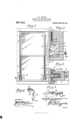
- Figure 1 is an elevation, partly in section, of a window equipped with lock lifts and holders, constructed in accord ance with this invention.
- Fig. 2 is an en larged vertical sectional view of the lock lift and holder.
- Fig. 3 is a horizontal sectional view of the same.
- Fig. 4 is a detail perspective view of the bolt actuating lever.
- Fig. 5 is a similar view of the sliding bolt.
- the lock lift and holder comprises in its construction a sliding bolt 1, uided in a casing 52 and actuated by a lever 8 to move the bolt into its engaging position.
- the lever is con nccted with a sash balancing and lifting spring 1, but an elastic cord may be substituted for the spring, and the lever may also be connected with an ordinary weighted cord, or other form of sash balance.
- the casing 52 which is mortised in the side of the sash 5, is composed of spaced vertical sides and an inner integral vertical connecting wall 6.
- the bottom of the casing is preferably formed by a block or piece 7, riveted or otherwise secured between the sides of the casing and spacing the sides and forming a support for the sliding bolt 1.
- the sliding bolt 1 which is arranged horizontally, is composed of a rectangular body portion and a rounded stem 8, extending through the wall 6 of the casing and through the side bar or member of the frame of the sash, and equipped at its outer end with a ring 9, or other suitable means for enabling it to be readily grasped by the operator.
- the rectangular body portion of the bolt rests upon the block or piece 7 and is provided in its upper edge with a straight longitudinal recess 10, receiving a guiding pin or rivet 11, which pierces the sides of the casing.
- the bolt slides upon the bottom of the casing and is guided by the same and by the pin 11, which also limits the sliding movement of the bolt and prevents the same from becoming disengaged from the lever.
- the lever 3 which is arranged in an upright position, is curved longitudinally to form angularly related arms, and is pivoted at an intermediate point between the sides of the casing by means of a pin or rivet 12.
- the lever is tapered longitudinally, and its lower terminal 13 is rounded and is fitted in an inclined bearing recess let, formed in the upper edge of the body portion of the bolt in rear of the guiding recess 10.
- the upper end 15 of the lever is bifurcated and is equipped with a pin 16, extending across the slot or bifurcation of the upper end of the lever and engaged by a hook 17, which has its shank 18 secured within the slotted end of the coiled spring 4.
- the spring when placed under tension, tends to draw the upper end of the lever upwardly and to move the engaging end of the bolt inwardly into engagement with the side of the win dow frame 19, which is equipped at the bottom with a keeper 20, consisting of a metallic plate provided with a recess conforming to the configuration of the end of the bolt and enabling the same to securely lock the sash in its closed position.
- a keeper 20 consisting of a metallic plate provided with a recess conforming to the configuration of the end of the bolt and enabling the same to securely lock the sash in its closed position.
- the frictional engagement of the bolt with the window frame is sufficient to hold the sash in any adjustment.
- each side of the sash is attached to the window frame by a screw eye 21, or other suitable means and each side of the sash may be equipped with a lock lift and holder, or only one lock lift may be employed and in such event an anti-friction roller should be mounted on the upper portion of the side of the sash not supplied with the sash lock.
- a horizontal slidable bolt guided in the casing and extending through the side of the sash and provided with ope 'ating means, said bolt being also provided in its upper edge at a point intermediate of its ends with a bearing recess, and an upright lever concealed within the casing and located above the bolt and fulcrumed at an intermediate point and having angularly related upper and lower arms, the upper arm being connected with the sash balance and the lower arm being fitted in the recess, whereby the sash balance will actuate the bolt and move the same to its engaging position.
- a device of the class described comprising a sash balancing spring provided at its lower end with a hook, a horizontally slidable bolt located below the spring and provided in its upper edge with a bearing recess and having operating means at its outer end adapted to extend through the side of the frame of a sash, and an upright lever located above the bolt and pivoted at an intermediate point and having angularly related uppe and lower arms, the lower arm being fitted in the recess of the bolt and the upper arm being bifurcated to receive the hook of the spring and having means for engaging the same.
- a device of the class described including a casing having a horizontal bottom guiding portion and designed to be mortised in the sash, a horizontal bolt consisting of a rectangular body portion slidable on the bottom of the casing and provided with an operating stem extending through the same and adapted to project exteriorly of a sash, said bolt being also providedin the upper edge of its body portion with a bearing recess and having a stem guiding recess in advance of the same, a pin mounted in the casing and extending through the guiding recess, and a curved lever concealed within the casing and pivoted at an intermediate point above the bolt and having its lower end fitting in the bearing recess of the said bolt and engaging the same, said lever being provided at its upper end with means for connecting it to a sash balance, whereby the latter is adapted to move the bolt to its engaging position.
Landscapes
- Engineering & Computer Science (AREA)
- Mechanical Engineering (AREA)
- Wing Frames And Configurations (AREA)
Description
G. D. SPATES.
WINDOW LIFT LOOK AND HOLDER.
APPLICATION, FILED JULY 23, 1910.
' 987,759. Patented Mar.28, 1911.
ATTORNEY TTNTED dTATS PATENT @FFTQE CHARLES ID. SPATES, OF DIGBY, NOVA SCUTIA, CANADA, ASSIGNOB OF ONE-HALF TO CLARENCE JAMESON, 0F DIGBY, NOVA SCOTIA, CANADA.
Specification of Letters Patent.
Patented Mar. 28, 1911.
Application filed July 28, 1910. Serial No. 574,293.
To all whom it may concern:
Be it known that I, CHARLES D. Srarns, a subject of the King of Great Britain, residing at Digby, in the Province of Nova Sco tia and Dominion of Canada, have invented a new and useful Window Lift-Lock and Holder, of which the following is a specification.
The invention relates to a lift lock and holder for window sashes.
The object of the present invention is to improve the construction of sash locks, and to provide a simple, inexpensive and efficient device, adapted to be readily applied to windows having balance sashes, and adapted to enable the same to be readily raised and lowered, and capable of holding the sash atany adjustment and of securely lockin g a sash in its closed position.
With these and other objects in view, the invention consists in the construction and novel combination of parts hereinafter fully described, illustrated in the accompanying drawing, and pointed out in the claims hereto appended; it being understood that various changes in the form, proportion, size and minor details of construction, within the scope of the claims, may be resorted to without departing from the spirit or sacrificing any of the advantages of the invention.
In the drawing: Figure 1 is an elevation, partly in section, of a window equipped with lock lifts and holders, constructed in accord ance with this invention. Fig. 2 is an en larged vertical sectional view of the lock lift and holder. Fig. 3 is a horizontal sectional view of the same. Fig. 4 is a detail perspective view of the bolt actuating lever. Fig. 5 is a similar view of the sliding bolt.
Like numerals of reference designate cor responding parts in all the figures of the drawing.
In the embodiment of the invention illustrated in the accompanying drawing, the lock lift and holder comprises in its construction a sliding bolt 1, uided in a casing 52 and actuated by a lever 8 to move the bolt into its engaging position. The lever is con nccted with a sash balancing and lifting spring 1, but an elastic cord may be substituted for the spring, and the lever may also be connected with an ordinary weighted cord, or other form of sash balance. The casing 52, which is mortised in the side of the sash 5, is composed of spaced vertical sides and an inner integral vertical connecting wall 6. The bottom of the casing is preferably formed by a block or piece 7, riveted or otherwise secured between the sides of the casing and spacing the sides and forming a support for the sliding bolt 1.
The sliding bolt 1, which is arranged horizontally, is composed of a rectangular body portion and a rounded stem 8, extending through the wall 6 of the casing and through the side bar or member of the frame of the sash, and equipped at its outer end with a ring 9, or other suitable means for enabling it to be readily grasped by the operator. The rectangular body portion of the bolt rests upon the block or piece 7 and is provided in its upper edge with a straight longitudinal recess 10, receiving a guiding pin or rivet 11, which pierces the sides of the casing. The bolt slides upon the bottom of the casing and is guided by the same and by the pin 11, which also limits the sliding movement of the bolt and prevents the same from becoming disengaged from the lever.
The lever 3, which is arranged in an upright position, is curved longitudinally to form angularly related arms, and is pivoted at an intermediate point between the sides of the casing by means of a pin or rivet 12. The lever is tapered longitudinally, and its lower terminal 13 is rounded and is fitted in an inclined bearing recess let, formed in the upper edge of the body portion of the bolt in rear of the guiding recess 10. The upper end 15 of the lever is bifurcated and is equipped with a pin 16, extending across the slot or bifurcation of the upper end of the lever and engaged by a hook 17, which has its shank 18 secured within the slotted end of the coiled spring 4. The spring, when placed under tension, tends to draw the upper end of the lever upwardly and to move the engaging end of the bolt inwardly into engagement with the side of the win dow frame 19, which is equipped at the bottom with a keeper 20, consisting of a metallic plate provided with a recess conforming to the configuration of the end of the bolt and enabling the same to securely lock the sash in its closed position. hen the bolt is withdrawn by hand from engagement with the window frame, the spring a will. operate to lift he sash, and when the bolt is released the spring will carry the same into engagement with the window frame.
The frictional engagement of the bolt with the window frame is sufficient to hold the sash in any adjustment.
The upper end of the spring l is attached to the window frame by a screw eye 21, or other suitable means and each side of the sash may be equipped with a lock lift and holder, or only one lock lift may be employed and in such event an anti-friction roller should be mounted on the upper portion of the side of the sash not supplied with the sash lock.
Having thus fully described my invention, what I claim as new and desire to secure by Letters Patent, is
1. In a device ofthe class described,the combination with a sash balance, of a cas ing designed to be mounted on a sash, a horizontal slidable bolt guided in the casing and extending through the side of the sash and provided with ope 'ating means, said bolt being also provided in its upper edge at a point intermediate of its ends with a bearing recess, and an upright lever concealed within the casing and located above the bolt and fulcrumed at an intermediate point and having angularly related upper and lower arms, the upper arm being connected with the sash balance and the lower arm being fitted in the recess, whereby the sash balance will actuate the bolt and move the same to its engaging position.
2. A device of the class described compris ing a sash balancing spring provided at its lower end with a hook, a horizontally slidable bolt located below the spring and provided in its upper edge with a bearing recess and having operating means at its outer end adapted to extend through the side of the frame of a sash, and an upright lever located above the bolt and pivoted at an intermediate point and having angularly related uppe and lower arms, the lower arm being fitted in the recess of the bolt and the upper arm being bifurcated to receive the hook of the spring and having means for engaging the same.
3. A device of the class described including a casing having a horizontal bottom guiding portion and designed to be mortised in the sash, a horizontal bolt consisting of a rectangular body portion slidable on the bottom of the casing and provided with an operating stem extending through the same and adapted to project exteriorly of a sash, said bolt being also providedin the upper edge of its body portion with a bearing recess and having a stem guiding recess in advance of the same, a pin mounted in the casing and extending through the guiding recess, and a curved lever concealed within the casing and pivoted at an intermediate point above the bolt and having its lower end fitting in the bearing recess of the said bolt and engaging the same, said lever being provided at its upper end with means for connecting it to a sash balance, whereby the latter is adapted to move the bolt to its engaging position. V
In testimony, that I claim the foregoing as my own, I have hereto affixed my signature in the presence of two witnesses.
CHARLES D. SPATES. lVitnesses H. A. P. SMITH, Cmrrom) SMITH.
Copies of this patent may be obtained for five cents each,
by addressing the Commissioner of Patents,
Washington, D. G.
Priority Applications (1)
| Application Number | Priority Date | Filing Date | Title |
|---|---|---|---|
| US1910574293 US987759A (en) | 1910-07-28 | 1910-07-28 | Window lift-lock and holder. |
Applications Claiming Priority (1)
| Application Number | Priority Date | Filing Date | Title |
|---|---|---|---|
| US1910574293 US987759A (en) | 1910-07-28 | 1910-07-28 | Window lift-lock and holder. |
Publications (1)
| Publication Number | Publication Date |
|---|---|
| US987759A true US987759A (en) | 1911-03-28 |
Family
ID=3056097
Family Applications (1)
| Application Number | Title | Priority Date | Filing Date |
|---|---|---|---|
| US1910574293 Expired - Lifetime US987759A (en) | 1910-07-28 | 1910-07-28 | Window lift-lock and holder. |
Country Status (1)
| Country | Link |
|---|---|
| US (1) | US987759A (en) |
-
1910
- 1910-07-28 US US1910574293 patent/US987759A/en not_active Expired - Lifetime
Similar Documents
| Publication | Publication Date | Title |
|---|---|---|
| US939480A (en) | Sash-lock. | |
| US1241192A (en) | Door-fastener. | |
| US987759A (en) | Window lift-lock and holder. | |
| US1185547A (en) | Door-stop. | |
| US614741A (en) | Sash-fastener | |
| US193992A (en) | Improvement in window-sash fasteners | |
| US643612A (en) | Door-catch. | |
| US611676A (en) | Combined weather-strip and door-check | |
| US82863A (en) | Necticut | |
| US59505A (en) | Improvement in sash holders or fastenings | |
| US317036A (en) | Transom-lifter | |
| US299402A (en) | Henry keppel | |
| US916274A (en) | Sash-lock. | |
| US141184A (en) | Improvement in sash-holders | |
| US913291A (en) | Adjustable ventilating sash-lock. | |
| US253563A (en) | Sash-fastener | |
| US792067A (en) | Sash-lock. | |
| US818547A (en) | Sash holder and lock. | |
| US1082638A (en) | Sash-fastener. | |
| US971569A (en) | Sash-fastener. | |
| US544053A (en) | Door-check | |
| US200753A (en) | Improvement in transom-lifters | |
| US326848A (en) | Sash-fastener | |
| US385599A (en) | Door-check | |
| US456715A (en) | Berry |