US987541A - Cement-brick machine. - Google Patents
Cement-brick machine. Download PDFInfo
- Publication number
- US987541A US987541A US55392410A US1910553924A US987541A US 987541 A US987541 A US 987541A US 55392410 A US55392410 A US 55392410A US 1910553924 A US1910553924 A US 1910553924A US 987541 A US987541 A US 987541A
- Authority
- US
- United States
- Prior art keywords
- pallet
- bars
- bricks
- frame
- cell
- Prior art date
- Legal status (The legal status is an assumption and is not a legal conclusion. Google has not performed a legal analysis and makes no representation as to the accuracy of the status listed.)
- Expired - Lifetime
Links
- 239000011449 brick Substances 0.000 title description 21
- 230000007246 mechanism Effects 0.000 description 4
- 238000010276 construction Methods 0.000 description 3
- 230000000994 depressogenic effect Effects 0.000 description 3
- 230000000284 resting effect Effects 0.000 description 3
- 239000004568 cement Substances 0.000 description 2
- 238000004519 manufacturing process Methods 0.000 description 2
- 239000011435 rock Substances 0.000 description 2
- BHELIUBJHYAEDK-OAIUPTLZSA-N Aspoxicillin Chemical compound C1([C@H](C(=O)N[C@@H]2C(N3[C@H](C(C)(C)S[C@@H]32)C(O)=O)=O)NC(=O)[C@H](N)CC(=O)NC)=CC=C(O)C=C1 BHELIUBJHYAEDK-OAIUPTLZSA-N 0.000 description 1
- 239000000470 constituent Substances 0.000 description 1
- 239000000463 material Substances 0.000 description 1
- 230000000630 rising effect Effects 0.000 description 1
Images

Classifications
-
- B—PERFORMING OPERATIONS; TRANSPORTING
- B28—WORKING CEMENT, CLAY, OR STONE
- B28B—SHAPING CLAY OR OTHER CERAMIC COMPOSITIONS; SHAPING SLAG; SHAPING MIXTURES CONTAINING CEMENTITIOUS MATERIAL, e.g. PLASTER
- B28B7/00—Moulds; Cores; Mandrels
- B28B7/24—Unitary mould structures with a plurality of moulding spaces, e.g. moulds divided into multiple moulding spaces by integratable partitions, mould part structures providing a number of moulding spaces in mutual co-operation
- B28B7/241—Detachable assemblies of mould parts providing only in mutual co-operation a number of complete moulding spaces
Definitions
- the crank 22 is manipulated, causing a rotation of the shaft 21, the shaft 21 through the instrumentality of the pinion 2-1, causing a rotation of the pinion 25 and of the stub shaft 26, the beveled pinion 27, thereon, meshing with the beveled pinion 2S, and causing a rotation of the shaft 29.
- the pinions 30 of which, fitting into the racks 31 which are secured to the side bars 15 of the cell frame, will cause the cell frame to be depressed, into the position shown in Fig.
Landscapes
- Engineering & Computer Science (AREA)
- Manufacturing & Machinery (AREA)
- Chemical & Material Sciences (AREA)
- Ceramic Engineering (AREA)
- Mechanical Engineering (AREA)
- Revetment (AREA)
Description
Patented Mar.21, 1911.
R HAM Hm O 00 BM? N ATM an Wm M Attorneys \WNN 2 SHEETS-SHEET 1.
o c o o o o o Wa o o o o o e a o a o a o c a O 0 a o G 0 o O 0 G 0 O O a O c 0 0 0 O o O o a /o C o o o o a 0 o o a u o o w Q 0 a OOOOOO ODOO E EEEE E MN G.A.BOOHER. GBMENT BRICK MACHINE. APPLICATION FILED APR. 7, 1910.
Patented Mar.21,1911.
2 BEEETS-SHEBT 2.
L 12 M J7 Inventor Witnesses Attorneys CLAUD A. BOOHER, OF LITTLE ROCK, ARKANSAS.
CEMENT-BRICK MACHINE.
Specification of Letters Patent.
Patented Mar. 21, 1911.
Application filed April 7, 1910. Serial No. 553,924.
To all whom it may concern:
Be it known that I, CLAUD A. BOOI-IER, a citizen of the United States, residing at Little Rock, in the county of Pulaski and State of Arkansas, have invented a new and useful Cement-Brick Machine, of which the following is a specification.
This invention relates to brick machines, such as are used particularly for manufactur ing cement bricks, although the machine of the present invention can be used for other kinds of work if desired.
The principal objects of the present invention are to improve and simplify the construction of such machines, as well as to increase their efficiency in operation and to decrease the expenses attendant upon their manufacture and use.
A further object of the invention is to provide improved means for disengaging the molded bricks from the cells or compartments in which they are formed.
A further object of the invention is to provide improved means for facilitating the removal of the molded bricks from the machine.
The drawings show typical embodiments merely, and it is to be understood that changes, properly falling within the scope of what is claimed, may be made, without departing from the spirit of the invention.
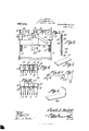
In the accompanying drawings,-Figure 1 is a side elevation of a brick machine constructed in accordance with the present invention, parts being broken away; Fig. 2 is a top plan thereof; Fig. 3 is an end elevation; Fig. at is a fragmental transverse sec tion, showing the cell frame depressed. Fig. 5 is a detail perspective of the ordinary form of pallet; Fig. 6 is a side elevation of an improved form of pallet; Fig. 7 is an end elevation of the pallet delineated in Fig. 6; Fig. 8 is a detail perspective of a pallet adapted to be used in forming corner bricks; Fig. 9 is a transverse section of one of the short cross bars, and Fig. 10 is a fragmental transverse section, showing the cell frame elevated.
The machine of the present invention is provided with an ejector element for ejecting the molded bricks from the cell members or elements in which they are formed. This ejector element preferably includes a frame, made up of side bars 1, endbars 2, intermediate longitudinal bars 3 and 4, and supports 5, the said supports being bolted at 6 to the side bars 1, and being braced by means of the rods 7 secured at their upper ends to the side barsl, and at their lower ends secured to the supports or legs 5, as shown.
The ejector means proper, connected with the ejector frame, preferably consists of pairs of vertically extended pallet supports 12, these pallet supports 12 being fixed to and rising from the side bars 1 and the intermediate longitudinal bars 3 and 1, the pallet supports 12 being arranged in pairs as shown, each pair of pallet supports, supporting the pallet 13, the outline of one form of which is seen most clearly in Fig. 5.
The cell element or frame, by means of which the bricks are molded, preferably consists of the side bars 15, the ends bars 16, the intermediate longitudinal bars 17, and the short cross bars 18 the short cross bars 18, cooperating with the several longitudinal bars, to form a plurality of cells.
In Fig. 9 of the drawings, the construction of the short cross bars is shown in detail. It will there be seen that they consist of spaced parallel plates 32, held apart by spacing blocks 33. The plates 32 are connected with the spacing blocks 33, by means of transverse rivets 34:, or like securing devices, the heads of which are disposed flush with the outer faces of the plates 32, so that there may be no protuberances to mar the bricks as they are formed. Tie bolts 35 are extended through the short cross bars 18, between the l constituent plates 32 thereof, the ends of the tie bolts 85, being, as seen most clearly in Fig. I, mounted in the side bars 15. At the ends of the device, are duplicate mechanisms, for raising and lowering the cell frame. A description of one of these mechanisms, will be given, it being understood that the description applies with equal propriety to the other of said mechanisms.
The ends of the side bars 1 of the ejector frame, are connected by a transverse tie bar 19. From this tie bar 19, and from the end bar 2 of the ejector frame, rise brackets 20. A shaft 21 is j ournaled for rotation in these brackets 20, one end of the said shaft 21 being extended beyond the tie bar 19. Upon the extended portion of the shaft 21 is a crank 22, and suitable pawl and ratchet mechanism 23, is adapted to hold the shaft 21 against rotation, the pawl portion being secured, as seen most clearly in Fig. 3, upon that bracket 20 which rises from the tie bar 19.
Secured to the shaft 21 is a pinion 24, in mesh with a larger pinion 25, secured to a stub shaft 26, journaled for rotation in the bracket 20 which is carried by the end bar 2. Upon this stub shaft 26, there is a beveled pinion 27, in mesh with a beveled pinion 28, carried by a transverse shaft 29, the ends of which. are journaled for rotation in the side bars 1 of the ejector frame. Located upon the transverse shaft 29, adjacent the ends thereof, are pinions 30, in mesh with racks 31, secured to and depending from the side bars 15 of the cell frame.
In place of the flat pallet 13, shown in Fig. 5, the modified pallet shown in Figs. 6 and 7 may, if desired, be employed. This modified pallet 38 has, upon its lower surface, grooves 36, adapted to receive the upper ends of the pallet supports 12. At the ends thereof, the pallet 38 is provided with downwardly disposed extensions 37 which converge slightly toward each other at their lower ends, as shown. The advantage of employing the pallet such as 88 is that this pallet can be mounted upon the pallet supports 12, when the cell structure is in lowered position, as shown in Fig. 4%, and, as the cell structure is raised, the converging extensions 37 fit into the upper ends of the different cells, and serve to guide the pallets properly into position.
lVhen it is desired to form corner bricks, the pallet shown in Fig. 8, and there denoted by the numeral 39 is employed. This pallet is inserted in the usual manner into the cell compartment.
The operation of the device as hereinbefore described, is as follows: When the brick machine is empty, the cell frame being elevated, as indicated in Fig. 10. one of the pallets 13 is fitted downward into each of the cells or compartments, until the said pallet rests upon a pair of the pallet supports 12, and is thereby held in position to close the lower end of the cell or compartment in which it is located. The cement or other material from which the bricks are to be formed, is then poured into the different cells or compartments, and after having been suitably t-amped therein, is molded into the form of the bricks, or other articles which are being fashioned in the cells. The bricks are then permitted to set or harden to a sufficient degree. and when they are ready to be removed from the machine, the crank 22 is manipulated, causing a rotation of the shaft 21, the shaft 21 through the instrumentality of the pinion 2-1, causing a rotation of the pinion 25 and of the stub shaft 26, the beveled pinion 27, thereon, meshing with the beveled pinion 2S, and causing a rotation of the shaft 29. the pinions 30 of which, fitting into the racks 31 which are secured to the side bars 15 of the cell frame, will cause the cell frame to be depressed, into the position shown in Fig.
l of the drawings. The several bricks which have thus been fashioned upon the pallets 12, will be left upstanding from the said pallets, and well above the now depressed cell frame. A suitable device of any desired character may then be thrust through the machine, between the several pallet supports 12, whereupon a complete row, or, indeed, several rows of bricks, together with their supporting pallets, may be lifted out of the machine. .Thus, two operators, mayreadily empty the machine in a short time.
It is to be understood that the machine of the present invention can be manufactured in any desired size, so as to handle any desired number of bricks in a single operation.
The brick machine of the present invention, is characterized by extreme simplicity and strength, in construction, as well as thorough efliciency and accuracy in operation. But two operators are required to manipulate the machine, and the daily output is very large.
Having thus described the invention what is claimed is V l. A device of the class described comprising a cell structure; a pallet support therein; and a pallet resting upon the support, the pallet having downwardly extended, converging end portions, adapted to engage with the walls of the cell structure to guide the pallet thereinto.
2. A device of the class described comprising a cell structure; a pallet support therein; a pallet resting upon the support, the pallet having downwardly extended, converging end portions, adapted to engage with the walls of the cell structure to guide the pallet thereinto; the pallet being interengaged with the support for limited sliding movement, transversely of the support, to hold the end portions of the pallet in position for engagement with the cell structure.
3. A device of the class described comprising a cell structure; a pallet support therein; a pallet resting upon the support, the pallethaving downwardly extended, converging end portions. adapted to engage with the walls of the cell structure to guide the pallet thereinto; there being a groove in the lower face of the pallet, adapted to receive the pallet support to position the end portions of the pallet for engagement with the walls of the cell structure.
l. In a device of the class described, an ejector frame consisting of side bars, end bars connecting the side bars, and intermediate bars parallel to the side bars and supported at their ends only by the end bars; pallet supports secured to the side bars and to the intermediate bars; a frame as my own, I have hereto affixed my signahaving a plurality of cells each of Which ture in the presence of two Witnesses. is ada ted to receive a )air of aallet suap0rt-s; and means for produciiig relatiire OLAUD BOOHER 5 movement between the ejector frame and the Wit e e cell frame. FRANK B. OOHSENREITER,
In testimony that I claim the foregoing C. E. DOYLE.
Copies of this patent may be obtained for five cents each, by addressing the Commissioner of Patents, Washington, D. C.
Priority Applications (1)
| Application Number | Priority Date | Filing Date | Title |
|---|---|---|---|
| US55392410A US987541A (en) | 1910-04-07 | 1910-04-07 | Cement-brick machine. |
Applications Claiming Priority (1)
| Application Number | Priority Date | Filing Date | Title |
|---|---|---|---|
| US55392410A US987541A (en) | 1910-04-07 | 1910-04-07 | Cement-brick machine. |
Publications (1)
| Publication Number | Publication Date |
|---|---|
| US987541A true US987541A (en) | 1911-03-21 |
Family
ID=3055880
Family Applications (1)
| Application Number | Title | Priority Date | Filing Date |
|---|---|---|---|
| US55392410A Expired - Lifetime US987541A (en) | 1910-04-07 | 1910-04-07 | Cement-brick machine. |
Country Status (1)
| Country | Link |
|---|---|
| US (1) | US987541A (en) |
-
1910
- 1910-04-07 US US55392410A patent/US987541A/en not_active Expired - Lifetime
Similar Documents
| Publication | Publication Date | Title |
|---|---|---|
| US1166312A (en) | Apparatus for making concrete blocks. | |
| US987541A (en) | Cement-brick machine. | |
| US777086A (en) | Brick-molding machine. | |
| US804423A (en) | Machine for making cement blocks. | |
| US30406A (en) | Brick-molding machine | |
| US917036A (en) | Multimolding two-side-delivery hand brick-machine. | |
| US1041991A (en) | Mold. | |
| US1100452A (en) | Artificial-stone machine. | |
| US930665A (en) | Machine for molding concrete blocks. | |
| US1183128A (en) | Device for placing metal reinforcing. | |
| US840911A (en) | Concrete-brick machine. | |
| US978600A (en) | Brick-machine. | |
| US29958A (en) | Brick-mold | |
| US26798A (en) | George a | |
| US816438A (en) | Cement-block machine. | |
| US1747708A (en) | Molding machine | |
| US2104293A (en) | Brick and tile machine | |
| US1075056A (en) | Baling-press. | |
| US913441A (en) | Mold for concrete-wall construction. | |
| US1161188A (en) | Molding-machine. | |
| US1030648A (en) | Baling-press. | |
| US1387263A (en) | Gbover c | |
| CN211392605U (en) | A transmission structure for goods shelves | |
| US892574A (en) | Brick-molding machine. | |
| US736849A (en) | Fruit-drier. |