US9874408B2 - Heat exchangers - Google Patents
Heat exchangers Download PDFInfo
- Publication number
- US9874408B2 US9874408B2 US14/094,356 US201314094356A US9874408B2 US 9874408 B2 US9874408 B2 US 9874408B2 US 201314094356 A US201314094356 A US 201314094356A US 9874408 B2 US9874408 B2 US 9874408B2
- Authority
- US
- United States
- Prior art keywords
- side wall
- fins
- heat exchanger
- tubing elements
- exchanger apparatus
- Prior art date
- Legal status (The legal status is an assumption and is not a legal conclusion. Google has not performed a legal analysis and makes no representation as to the accuracy of the status listed.)
- Active, expires
Links
Images


Classifications
-
- F—MECHANICAL ENGINEERING; LIGHTING; HEATING; WEAPONS; BLASTING
- F28—HEAT EXCHANGE IN GENERAL
- F28F—DETAILS OF HEAT-EXCHANGE AND HEAT-TRANSFER APPARATUS, OF GENERAL APPLICATION
- F28F1/00—Tubular elements; Assemblies of tubular elements
- F28F1/006—Tubular elements; Assemblies of tubular elements with variable shape, e.g. with modified tube ends, with different geometrical features
-
- B—PERFORMING OPERATIONS; TRANSPORTING
- B23—MACHINE TOOLS; METAL-WORKING NOT OTHERWISE PROVIDED FOR
- B23P—METAL-WORKING NOT OTHERWISE PROVIDED FOR; COMBINED OPERATIONS; UNIVERSAL MACHINE TOOLS
- B23P15/00—Making specific metal objects by operations not covered by a single other subclass or a group in this subclass
- B23P15/26—Making specific metal objects by operations not covered by a single other subclass or a group in this subclass heat exchangers or the like
-
- F—MECHANICAL ENGINEERING; LIGHTING; HEATING; WEAPONS; BLASTING
- F28—HEAT EXCHANGE IN GENERAL
- F28D—HEAT-EXCHANGE APPARATUS, NOT PROVIDED FOR IN ANOTHER SUBCLASS, IN WHICH THE HEAT-EXCHANGE MEDIA DO NOT COME INTO DIRECT CONTACT
- F28D1/00—Heat-exchange apparatus having stationary conduit assemblies for one heat-exchange medium only, the media being in contact with different sides of the conduit wall, in which the other heat-exchange medium is a large body of fluid, e.g. domestic or motor car radiators
- F28D1/02—Heat-exchange apparatus having stationary conduit assemblies for one heat-exchange medium only, the media being in contact with different sides of the conduit wall, in which the other heat-exchange medium is a large body of fluid, e.g. domestic or motor car radiators with heat-exchange conduits immersed in the body of fluid
- F28D1/04—Heat-exchange apparatus having stationary conduit assemblies for one heat-exchange medium only, the media being in contact with different sides of the conduit wall, in which the other heat-exchange medium is a large body of fluid, e.g. domestic or motor car radiators with heat-exchange conduits immersed in the body of fluid with tubular conduits
- F28D1/047—Heat-exchange apparatus having stationary conduit assemblies for one heat-exchange medium only, the media being in contact with different sides of the conduit wall, in which the other heat-exchange medium is a large body of fluid, e.g. domestic or motor car radiators with heat-exchange conduits immersed in the body of fluid with tubular conduits the conduits being bent, e.g. in a serpentine or zig-zag
- F28D1/0472—Heat-exchange apparatus having stationary conduit assemblies for one heat-exchange medium only, the media being in contact with different sides of the conduit wall, in which the other heat-exchange medium is a large body of fluid, e.g. domestic or motor car radiators with heat-exchange conduits immersed in the body of fluid with tubular conduits the conduits being bent, e.g. in a serpentine or zig-zag the conduits being helically or spirally coiled
- F28D1/0473—Heat-exchange apparatus having stationary conduit assemblies for one heat-exchange medium only, the media being in contact with different sides of the conduit wall, in which the other heat-exchange medium is a large body of fluid, e.g. domestic or motor car radiators with heat-exchange conduits immersed in the body of fluid with tubular conduits the conduits being bent, e.g. in a serpentine or zig-zag the conduits being helically or spirally coiled the conduits having a non-circular cross-section
-
- F—MECHANICAL ENGINEERING; LIGHTING; HEATING; WEAPONS; BLASTING
- F28—HEAT EXCHANGE IN GENERAL
- F28F—DETAILS OF HEAT-EXCHANGE AND HEAT-TRANSFER APPARATUS, OF GENERAL APPLICATION
- F28F1/00—Tubular elements; Assemblies of tubular elements
- F28F1/02—Tubular elements of cross-section which is non-circular
- F28F1/022—Tubular elements of cross-section which is non-circular with multiple channels
-
- F—MECHANICAL ENGINEERING; LIGHTING; HEATING; WEAPONS; BLASTING
- F28—HEAT EXCHANGE IN GENERAL
- F28F—DETAILS OF HEAT-EXCHANGE AND HEAT-TRANSFER APPARATUS, OF GENERAL APPLICATION
- F28F1/00—Tubular elements; Assemblies of tubular elements
- F28F1/02—Tubular elements of cross-section which is non-circular
- F28F1/025—Tubular elements of cross-section which is non-circular with variable shape, e.g. with modified tube ends, with different geometrical features
-
- F—MECHANICAL ENGINEERING; LIGHTING; HEATING; WEAPONS; BLASTING
- F28—HEAT EXCHANGE IN GENERAL
- F28F—DETAILS OF HEAT-EXCHANGE AND HEAT-TRANSFER APPARATUS, OF GENERAL APPLICATION
- F28F1/00—Tubular elements; Assemblies of tubular elements
- F28F1/10—Tubular elements and assemblies thereof with means for increasing heat-transfer area, e.g. with fins, with projections, with recesses
- F28F1/12—Tubular elements and assemblies thereof with means for increasing heat-transfer area, e.g. with fins, with projections, with recesses the means being only outside the tubular element
- F28F1/34—Tubular elements and assemblies thereof with means for increasing heat-transfer area, e.g. with fins, with projections, with recesses the means being only outside the tubular element and extending obliquely
-
- F—MECHANICAL ENGINEERING; LIGHTING; HEATING; WEAPONS; BLASTING
- F28—HEAT EXCHANGE IN GENERAL
- F28F—DETAILS OF HEAT-EXCHANGE AND HEAT-TRANSFER APPARATUS, OF GENERAL APPLICATION
- F28F17/00—Removing ice or water from heat-exchange apparatus
- F28F17/005—Means for draining condensates from heat exchangers, e.g. from evaporators
-
- F—MECHANICAL ENGINEERING; LIGHTING; HEATING; WEAPONS; BLASTING
- F28—HEAT EXCHANGE IN GENERAL
- F28F—DETAILS OF HEAT-EXCHANGE AND HEAT-TRANSFER APPARATUS, OF GENERAL APPLICATION
- F28F1/00—Tubular elements; Assemblies of tubular elements
- F28F1/10—Tubular elements and assemblies thereof with means for increasing heat-transfer area, e.g. with fins, with projections, with recesses
- F28F1/12—Tubular elements and assemblies thereof with means for increasing heat-transfer area, e.g. with fins, with projections, with recesses the means being only outside the tubular element
- F28F1/24—Tubular elements and assemblies thereof with means for increasing heat-transfer area, e.g. with fins, with projections, with recesses the means being only outside the tubular element and extending transversely
- F28F1/26—Tubular elements and assemblies thereof with means for increasing heat-transfer area, e.g. with fins, with projections, with recesses the means being only outside the tubular element and extending transversely the means being integral with the element
-
- F—MECHANICAL ENGINEERING; LIGHTING; HEATING; WEAPONS; BLASTING
- F28—HEAT EXCHANGE IN GENERAL
- F28F—DETAILS OF HEAT-EXCHANGE AND HEAT-TRANSFER APPARATUS, OF GENERAL APPLICATION
- F28F2260/00—Heat exchangers or heat exchange elements having special size, e.g. microstructures
- F28F2260/02—Heat exchangers or heat exchange elements having special size, e.g. microstructures having microchannels
-
- Y—GENERAL TAGGING OF NEW TECHNOLOGICAL DEVELOPMENTS; GENERAL TAGGING OF CROSS-SECTIONAL TECHNOLOGIES SPANNING OVER SEVERAL SECTIONS OF THE IPC; TECHNICAL SUBJECTS COVERED BY FORMER USPC CROSS-REFERENCE ART COLLECTIONS [XRACs] AND DIGESTS
- Y10—TECHNICAL SUBJECTS COVERED BY FORMER USPC
- Y10T—TECHNICAL SUBJECTS COVERED BY FORMER US CLASSIFICATION
- Y10T29/00—Metal working
- Y10T29/49—Method of mechanical manufacture
- Y10T29/4935—Heat exchanger or boiler making
- Y10T29/49391—Tube making or reforming
Definitions
- the present invention relates to heat exchangers having one or several substantially flat and rigid elongated tubing elements.
- a heat exchanger is hereby generally known to provide for an exchange of thermal energy between a first medium such as, for example, water and/or a cooling agent, and a second medium such as, for example, air.
- EP 1 840 494 A2 discloses a heat exchanger, whereby the heat exchanger comprises a profile having two flat tubes with several channels and whereby the tubes are connected by means of a bar.
- the profile is a one-piece profile and may consist of aluminium or an aluminium alloy.
- DE 20 2008 006 379 U1 discloses an aluminium or aluminium alloy profile, which can be used for tubes for heat exchangers.
- the profile has a central channel and several further channels arranged around the central channel.
- DE 2 209 325 discloses a tube for heat exchangers having a helical structure. Furthermore, DE 2 209 329 discloses heat exchanger tubes having ribs on the inner side and the outer side of the tube.
- GB 1 390 782 discloses a heat-exchange tubing having spaced metal fins projecting inwardly of the tubing from the wall sections of the tubing and extending longitudinally of the tubing.
- EP 0 640 803 A1 relates to heat transfer coil, where a second piece of tubing is wound around the first piece of tubing while the first piece is straight and where the first piece of tubing is then formed to define the overall coil shape and then the first and second pieces of tubing internally sized by internal pressurization to also force the two pieces of tubing to intimate contact with each other.
- a heat exchanger means comprising several substantially flat and rigid elongated tubing elements, whereby the tubing elements are forming a substantially overall cylindrical structure having a central longitudinal axis and that the tubing elements are spirally curved around the central longitudinal axis and interleaved in the structure, whereby the tubing elements have a plurality of fins in at least one of the outer surfaces of the first side wall and/or of the second side wall and whereby the fins are at least partially covered by covering wall, whereby the tubing elements are at least partially tilted or at least partially tilted and sloped and at least partially helically wound and/or twisted so as to form at least a part of a helical structure, whereby preferably the helical structure has an overall cylindrical structure and/or that the helical structure is formed in a cylindrical shape.
- the tubing element having a plurality of fins on at least one of the outer surfaces of the first side wall and/or of the second side wall and whereby the fins are at least partially covered by a covering wall, increases the tubing element surface for a better heat exchange between said second medium, such as air, and the heat exchanger.
- the helical structure of the tubing element is determined merely by variables radius r, angle ⁇ and angle ⁇ .
- Radius r defines the distance between the center of the tubing element and the central longitudinal axis X of the heat exchanger.
- Angle ⁇ defines the slope of the tubing element and extends between the central longitudinal axis X of the heat exchanger and the central axis Z of the tubing element.
- Angle ⁇ defines the tilt of the tubing element and extends between the central longitudinal axis X of the heat exchanger and the central transversal axis Y of the tubing element.
- the tubing element being tilted while at least partially helically wound and/or twisted so as to form at least a part of a helical structure, is more efficient with less material. Also the heat exchanger needs a smaller volume in the whole heat exchanger system, due to the compact set of tubing elements.
- this tubing element being tilted while being at least partially helically wound and/or twisted so as to form at least a part of a helical structure, effects a better interaction between a second medium such as air and the surface of the tubing element, due to the tilted orientation of the tubing element.
- Such a tubing element for a heat exchanger may be an elongated heat exchanger microchannel tube.
- Such an elongated heat exchanger microchannel tube may have a first and a second open end.
- Heat transfer vapor or fluid may fill a heat exchanger microchannel tube and may flow from one end of the microchannel tube to the other end.
- microchannel is also known as microport.
- a second medium such as air may flow around the outer sides of the tubing element and may transport the heat from the tube away or vice versa.
- the surface for heat exchange is increased.
- the efficiency of the heat exchanger may be significantly improved.
- the width of the first side wall and the second side wall is approximately at least 10 times larger than the distance between the first side wall and the second side wall and/or that the first side wall and second side wall are connected respectively on both sides by a rounded connection wall.
- the width of the first side wall and/or the second side wall may be equal and/or chosen within a range of about 10 mm to about 30 mm. Preferably, the width of the first side wall and/or the second side wall may be about 15 mm.
- the distance between the first side wall and the second side wall may be chosen respectively, i.e. within a range of about 1 mm to about 3 mm. Preferably the distance may be about 1.5 mm.
- the tubing element is at least partially tilted or at least partially tilted and sloped and at least partially helically wound and/or twisted so as to form at least a part of a helical structure, whereby preferably the helical structure has an overall cylindrical structure and/or that the helical structure is formed in a cylindrical shape.
- the structure according to the present invention of heat exchangers allows a more efficient heat exchange and a more compact structure of heat exchangers.
- the heat exchanger may be embodied as a heat exchanger.
- the fins are arranged between the covering wall and at least one of the outer surfaces of the first side wall and/or of the second side wall and that the covering wall and the outer surface are substantially parallel.
- interleaved tubing elements are arranged one upon the other.
- the first ends of adjacent tubing elements may be connected by a connecting means, whereby preferably the connecting means is a connector tubing element, which is for instance at least partially U-shaped bended.
- the second ends of adjacent tubing elements may be connected by a connecting means, whereby preferably the connecting means comprises plurality of connector tubing elements and a central connector portion, whereby for instance the connector tubing elements and the central connector portion are arranged in star-shaped manner.
- the tubing element has a plurality of fins on both of the outer surfaces of the first side wall and of the second side wall.
- the fins may be monoblock fins.
- the fins may be perpendicularly arranged on the at least one of the outer surfaces of the first side wall and/or of the second side wall.
- the fins are inclined arranged on the at least one of the outer surfaces of the first side wall and/or of the second side wall, whereby exemplarily the angle between the fins and the outer surface is substantially perpendicular.
- the fins may merely extend along the whole width of at least one of the outer surfaces of the first side wall and/or of the second side wall and/or are curved.
- the fins are arranged along a curve extending along the whole width of at least one of the outer surfaces of the first side wall and/or of the second side wall and/or are curved, whereby between the fins being arranged along a curve is a pitch and/or gap.
- the fins are arranged in a plurality of rows, preferably substantially parallel rows and/or preferably along at least a part of the length of the tubing element.
- tubing elements may comprise at least one microchannel, preferably several microchannels with a round or circular cross-section and/or several microchannels with an angular cross-section, exemplarily several microchannels with a triangular cross-section and/or several microchannels with quadrangular cross-section are provided.
- microchannels may be arranged with an off-set to each other, whereby exemplarily all microchannels are arranged with an off-set to each other, whereby preferably the off-set causes chamfers and/or grooves within the first side wall and/or the second side wall.
- the heat exchangers are condensers or evaporators or radiators or coolers.
- a tubing element for a heat exchanger comprising the tubing element features as defined in any of claims 1 to 14 .
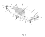
- FIG. 1 is a perspective view of a part of the tubing element according to the present invention in detail
- FIGS. 2 a and 2 b are a further perspective view of a part of the tubing element according to the present invention in detail in a first and second embodiment.
- FIG. 3 is a further perspective view of a part of the tubing element according to the present invention in a helical structure.
- FIG. 4 is a side elevation of the heat exchanger in a first embodiment according to the present invention.
- FIG. 5 is a perspective view of a tubing element for a heat exchanger with connecting means.
- FIG. 6 is a further perspective view of the tubing element according to FIG. 5 .
- FIG. 7 is a perspective view of interconnected tubing elements according to the present invention for a heat exchanger.
- FIG. 8 is a further perspective view of interconnected tubing elements for the heat exchanger according to the present invention according to FIG. 7 .
- FIG. 9 is a side elevation of a heat exchanger according to the present invention.
- FIG. 10 is a perspective view of the embodiment of the heat exchanger according to FIG. 9 .
- FIG. 1 shows a detailed perspective view of an elongated tubing element 10 having a plurality of microchannels 90 with quadrangular cross-section.
- the tubing element is a rigid elongated heat exchanger tubing having at least a first end 20 and a second end 30 and having a first side wall 40 and second side wall 50 .
- the first side wall 40 and the second side wall 50 are arranged substantially parallel to each other and the distance d between the first side wall 40 and the second side wall 50 is considerably smaller than the width W of the first side wall 40 and the second side wall 50 .
- the tubing element has a substantially overall flat tubing structure.
- the width W of the first side wall 40 and the second side wall 50 is approximately at least ten times larger than the distance d between the first side wall 40 .
- the second side wall 50 and the first side wall and the second side wall 40 , 50 are connected respectively on both sides by a rounded connection wall 45 , 55 .
- the width W of the first side wall 40 and the second side wall 50 is equal and chosen within a range of about 10 mm to 30 mm.
- the width W of the first side wall and the second side wall 40 , 50 is about 15 mm.
- the distance d is thus chosen with a value of about 1.5 mm.
- the distance between the first side wall 40 and the second side wall 50 is chosen respectively to the width values of the first side wall 40 and the second side wall 50 , i.e. normally within a range of about 1 mm to 3 mm.
- the tubing element 10 is at least partially tilted and sloped and also at least partially helically wound and twisted as shown in FIG. 2 a so as to form at least a part of a helical structure (see FIG. 3 ), whereby the helical structure has an overall cylindrical structure and the helical structure is formed in a cylindrical shape.
- the tubing element 10 is forming an overall cylindrical structure having a central longitudinal axis X, said tubing element 10 being spatially curved around the central longitudinal axis X and interleaved in the structure (see FIG. 4 ) of several equal tubing elements 10 .
- the tubing elements 10 have a plurality of fins 60 on both outer surfaces 42 , 52 of the first side wall 40 and the second side wall 50 , as can be seen in FIGS. 1, 2 a and 3 .
- the helical structure of the tubing element 10 is determined merely by variables radius r, angle ⁇ and angle ⁇ .
- Radius r defines the distance between the inner side wall 40 of the tubing element 10 at the intersection of the central axis Z and the central transversal axis Y, both of the tubing element 10 and the central longitudinal axis X of the heat exchanger 100 .
- Angle ⁇ defines the slope of the tubing element 10 and extends between the central longitudinal axis X of the heat exchanger means 100 and the central axis Z of the tubing element 10 .
- Angle ⁇ defines the tile of the tubing element 10 and extends between the central longitudinal axis X of the heat exchanger 100 and the central transversal axis Y of the tubing element 10 .
- the fins 60 are arranged between the covering walls 70 , 80 and the outer surfaces 42 , 52 of the first side wall 40 and the second side wall 50 . Moreover, the covering wall 70 , 80 and the outer surfaces 42 , 52 of the first side wall 40 and the second side wall 50 are substantially parallel. However, the covering wall 70 , 80 and the outer surfaces 42 , 52 of the first side wall 40 and the second side wall 50 are not directly connected to each other so that e.g. a cooling medium may flow through the fins 60 arranged within the space provided by the covering wall 70 , 80 and the outer surfaces 42 , 52 of the first side wall 40 and the second side wall 50 .
- the cooling medium may enter the space also from the sides of the rounded connection walls 45 , 55 .
- the fins 60 are perpendicularly arranged on the outer surfaces 42 , 52 of the first side wall 40 and the second side wall 50 .
- the fins 60 are inclined arranged on the outer surfaces 42 , 52 of the first side wall 40 and the second side wall 50 , whereby exemplarily the angle between the fin 60 and the outer surface 42 , 52 is substantially perpendicular.
- the fins 60 merely extend along the whole width of the outer surfaces 42 , 52 of the first side wall 40 and the second side wall 50 and are curved. Furthermore, the fins 60 are arranged along a curve extending along the whole width of the outer surfaces 42 , 52 of the first side wall 40 and the second side wall 50 . Moreover, between the fins 60 several gaps 62 are provided. Through the gaps 62 the medium, e.g. a cooling or heating medium may pass.
- a cooling or heating medium may pass.
- the fins 60 and the curve of fin 60 and the connection walls 45 , 55 are arranged such to each other that they enclose an angle ⁇ .
- the angle ⁇ is chosen in the embodiment shown in FIGS. 1 to 4 within a range about 30° to about 60°, here in an angle of about 45°.
- An angle of about 45° between the fins 60 and the curve of fins 60 and at least one of the connection walls 45 , 55 is considered to be substantially neutral, in particular as a neutral arrangement with respect to the interference with e.g. fans or the like, which may be connected or used together with the heat exchanger 100 comprising such tubing elements 10 , as e.g. shown in FIGS. 4, 9 and 10 .
- FIG. 2 b shows an alternative embodiment of a tubing element 10 ′, which is almost identical with the embodiment shown in FIG. 2 a .
- the tubing element 10 ′ comprises fins 60 ′ which merely extend along the whole width W of the outer surfaces 42 , 52 of the first side wall 40 and the second sidewall 50 .
- the tubing elements 10 are tilted and sloped and helical wound and twisted so as to form a part of a helical structure, whereby this helical structure has an overall cylindrical structure.
- tubing elements are interleaved and arranged one upon the other to a heat exchanger 100 , as shown in FIG. 4 . Also, the central longitudinal axis is shown.
- FIG. 5 shows a non-tilted and unwound rigid elongated tubing element 10 for heat exchanger 100 according to the present invention.
- the tubing element 10 has the same structural and functional features as described with respect to the tubing element 10 shown in FIGS. 1 to 4 .
- the tubing element 10 comprises at its first end 20 and at its second end 30 a collecting portion 21 , 31 , which is reducing the width W of the first side wall 40 and the second side wall 50 to a smaller width.
- the collecting portions 21 , 31 are equipped with tubular elements 22 , 32 , i.e. tubular connectors with a circular cross-section by means of which the tubing element 10 may be connected with another tubing element or any connecting means, e.g. the first and second connecting means 25 and 35 as shown in FIGS. 7, 8, 9 and 10 .
- tubular elements 22 , 32 i.e. tubular connectors with a circular cross-section by means of which the tubing element 10 may be connected with another tubing element or any connecting means, e.g. the first and second connecting means 25 and 35 as shown in FIGS. 7, 8, 9 and 10 .
- FIG. 6 shows a tubing element 10 according to FIG. 5 , whereby the tubing element 10 shown in FIG. 6 has been partially tilted and sloped and partially helically wound and twisted so as to form at least a part of a helical structure.
- the so formed rigid elongated tubing elements 10 for the heat exchanger 100 may be attached to another, equally formed further tubing element 10 . Both tubing elements 10 are connected by a first connecting means 25 .
- This connecting means 25 is a connector tubing element 25 , which is U-shaped bended, see FIG. 7 .
- FIG. 8 is another perspective view of the arrangement of tubing elements as shown in FIG. 7 .
- the so connected tubing elements 10 may be further combined to an overall cylindrical structure of a heat exchanger 100 , as shown in FIGS. 9 and 10 .
- the second end 30 of adjacent tubing elements 10 are connected by a second connecting means 35 .
- the central longitudinal axis is shown in FIG. 9 .
- the second connecting means 35 comprises a plurality of connected tubing elements 36 and a central connector portion 37 , whereby the connector tubing elements 36 and the central connector portion 37 are arranged in a star-shaped manner.
- the connector tubing element 36 form alternatingly an inlet or an outlet.
- the inlet connector tubing elements 36 are connected with the inlet portion 38 of the central connector portion 37 and the outlet connector tubing elements 36 are connected with the outlet portion 39 of the central connector portion 38 .
- inlet and outlet function may be interchanged, i.e. the inlet may be the outlet or vice versa.
Landscapes
- Engineering & Computer Science (AREA)
- Physics & Mathematics (AREA)
- Mechanical Engineering (AREA)
- Thermal Sciences (AREA)
- General Engineering & Computer Science (AREA)
- Geometry (AREA)
- Heat-Exchange Devices With Radiators And Conduit Assemblies (AREA)
Abstract
Description
Claims (15)
Priority Applications (1)
| Application Number | Priority Date | Filing Date | Title |
|---|---|---|---|
| US14/094,356 US9874408B2 (en) | 2012-11-30 | 2013-12-02 | Heat exchangers |
Applications Claiming Priority (4)
| Application Number | Priority Date | Filing Date | Title |
|---|---|---|---|
| US201261731726P | 2012-11-30 | 2012-11-30 | |
| US201261731715P | 2012-11-30 | 2012-11-30 | |
| US201261731738P | 2012-11-30 | 2012-11-30 | |
| US14/094,356 US9874408B2 (en) | 2012-11-30 | 2013-12-02 | Heat exchangers |
Publications (2)
| Publication Number | Publication Date |
|---|---|
| US20140151008A1 US20140151008A1 (en) | 2014-06-05 |
| US9874408B2 true US9874408B2 (en) | 2018-01-23 |
Family
ID=50824288
Family Applications (3)
| Application Number | Title | Priority Date | Filing Date |
|---|---|---|---|
| US14/094,230 Active 2034-05-29 US9733024B2 (en) | 2012-11-30 | 2013-12-02 | Tubing element with fins for a heat exchanger |
| US14/094,356 Active 2034-03-13 US9874408B2 (en) | 2012-11-30 | 2013-12-02 | Heat exchangers |
| US14/094,279 Abandoned US20140182827A1 (en) | 2012-11-30 | 2013-12-02 | Tubing Element for a Heat Exchanger |
Family Applications Before (1)
| Application Number | Title | Priority Date | Filing Date |
|---|---|---|---|
| US14/094,230 Active 2034-05-29 US9733024B2 (en) | 2012-11-30 | 2013-12-02 | Tubing element with fins for a heat exchanger |
Family Applications After (1)
| Application Number | Title | Priority Date | Filing Date |
|---|---|---|---|
| US14/094,279 Abandoned US20140182827A1 (en) | 2012-11-30 | 2013-12-02 | Tubing Element for a Heat Exchanger |
Country Status (1)
| Country | Link |
|---|---|
| US (3) | US9733024B2 (en) |
Cited By (1)
| Publication number | Priority date | Publication date | Assignee | Title |
|---|---|---|---|---|
| US12152836B2 (en) | 2018-09-19 | 2024-11-26 | Carrier Corporation | Heat recovery ventilator |
Families Citing this family (4)
| Publication number | Priority date | Publication date | Assignee | Title |
|---|---|---|---|---|
| USD805616S1 (en) * | 2015-04-30 | 2017-12-19 | Samwon Industrial Co., Ltd. | Fin tube assembly for heat exchanger |
| BR112020006005B1 (en) * | 2017-09-26 | 2023-01-31 | Carlos Quesada Saborio | APPARATUS AND METHOD |
| CN109332998B (en) * | 2018-09-13 | 2020-01-21 | 湖北三江航天红阳机电有限公司 | Manufacturing method of integrated empennage with double-layer skin of ultra-long thin-wall aluminum alloy sandwich grid rib |
| EP3686536B1 (en) * | 2019-01-22 | 2021-05-26 | ABB Power Grids Switzerland AG | Evaporator and manufacturing method |
Citations (62)
| Publication number | Priority date | Publication date | Assignee | Title |
|---|---|---|---|---|
| US384202A (en) | 1888-06-05 | g-rove | ||
| GB117529A (en) | 1917-09-07 | 1918-07-25 | Walter Martin Taylor | Improvements in Gas-fired Water-heaters or Steam-generators. |
| US1458128A (en) * | 1919-10-13 | 1923-06-12 | Edward T Curran | Radiator |
| US1721284A (en) * | 1926-06-21 | 1929-07-16 | Mccord Radiator & Mfg Co | Radiator construction |
| US1791528A (en) * | 1926-02-25 | 1931-02-10 | Frigidaire Corp | Refrigerating apparatus |
| US1826344A (en) * | 1930-09-23 | 1931-10-06 | Res & Dev Corp | Heat exchange element |
| US1988224A (en) * | 1935-01-15 | Radiator | ||
| US1992561A (en) * | 1934-02-12 | 1935-02-26 | American Radiator & Standard | Method of heat transfer |
| US2834582A (en) * | 1953-06-24 | 1958-05-13 | Kablitz Richard | Plate heat exchanger |
| US3662582A (en) | 1970-05-18 | 1972-05-16 | Noranda Metal Ind | Heat-exchange tubing and method of making it |
| US3692100A (en) | 1971-07-09 | 1972-09-19 | United Brands Co | Mobile refrigerator shipping container unit |
| US3727682A (en) * | 1970-02-24 | 1973-04-17 | Peerless Of America | Heat exchangers and the method of making the same |
| DE2209325A1 (en) | 1970-05-18 | 1973-09-13 | Noranda Metal Ind | HEAT EXCHANGE TUBE WITH INTERNAL RIBS AND METHOD OF ITS MANUFACTURING |
| GB1390782A (en) | 1972-03-02 | 1975-04-16 | Noranda Metal Ind | Heat-exchange tubing |
| US4171015A (en) * | 1977-03-28 | 1979-10-16 | Caterpillar Tractor Co. | Heat exchanger tube and method of making same |
| US4341088A (en) | 1980-06-11 | 1982-07-27 | Mei Viung C | Highway vehicle exhaust gas refrigeration system |
| US4349489A (en) | 1979-07-26 | 1982-09-14 | Alain Gaget | Jet for the production of a vaporized idling mixture in an internal combustion engine |
| US4397331A (en) | 1978-09-29 | 1983-08-09 | Honeywell Inc. | Fluid flow control valve with maximized noise reduction |
| DE3815647A1 (en) | 1987-06-05 | 1988-12-22 | Sueddeutsche Kuehler Behr | Round heat exchanger, in particular for refrigerants (refrigerating media) of air conditioners |
| WO1989006774A1 (en) | 1988-01-19 | 1989-07-27 | Multistack International Pty. Ltd. | Improvements in heating and cooling systems |
| US4860993A (en) | 1988-01-14 | 1989-08-29 | Teledyne Industries, Inc. | Valve design to reduce cavitation and noise |
| WO1994016272A1 (en) | 1993-01-15 | 1994-07-21 | Joseph Le Mer | Heat exchanger element and method and device for producing same |
| EP0640803A1 (en) | 1991-03-18 | 1995-03-01 | Electric Power Research Institute | Spiral flighted double walled heat exchanger |
| US5490559A (en) * | 1994-07-20 | 1996-02-13 | Dinulescu; Horia A. | Heat exchanger with finned partition walls |
| US5505257A (en) * | 1993-06-18 | 1996-04-09 | Goetz, Jr.; Edward E. | Fin strip and heat exchanger construction |
| US5765630A (en) * | 1996-09-19 | 1998-06-16 | Siemens Electric Limited | Radiator with air flow directing fins |
| US5775187A (en) * | 1993-04-30 | 1998-07-07 | Nikolai; Zoubkov | Method and apparatus of producing a surface with alternating ridges and depressions |
| US6250602B1 (en) | 1999-01-18 | 2001-06-26 | Jansen's Aircraft Systems Controls, Inc. | Positive shut-off metering valve with axial thread drive |
| US6272867B1 (en) | 1999-09-22 | 2001-08-14 | The Coca-Cola Company | Apparatus using stirling cooler system and methods of use |
| US6279333B1 (en) | 2000-03-14 | 2001-08-28 | Industry Heating And Cooling, Inc. | Mobile industrial air cooling apparatus |
| US6332327B1 (en) | 2000-03-14 | 2001-12-25 | Hussmann Corporation | Distributed intelligence control for commercial refrigeration |
| US20020023737A1 (en) * | 2000-05-22 | 2002-02-28 | Hao Li Jia | Stacked-type heat dissipating apparatus |
| JP2002153931A (en) | 2000-11-21 | 2002-05-28 | Mitsubishi Heavy Ind Ltd | Heat exchange tube and finless heat exchanger |
| US6481216B2 (en) | 1999-09-22 | 2002-11-19 | The Coca Cola Company | Modular eutectic-based refrigeration system |
| US6546999B1 (en) * | 1998-07-10 | 2003-04-15 | Visteon Global Technologies, Inc. | Flat tubes for heat exchanger |
| US6564563B2 (en) | 2001-06-29 | 2003-05-20 | International Business Machines Corporation | Logic module refrigeration system with condensation control |
| US6637452B1 (en) | 2002-10-08 | 2003-10-28 | Fisher Controls International, Inc. | Valve with self-cleaning trim |
| US6647735B2 (en) | 2000-03-14 | 2003-11-18 | Hussmann Corporation | Distributed intelligence control for commercial refrigeration |
| US6662588B2 (en) | 2001-05-14 | 2003-12-16 | Vantage Equipment Corp. | Modular liquid-cooled air conditioning system |
| US6688125B2 (en) | 2000-06-28 | 2004-02-10 | Toshiba Carrier Corporation | Refrigerating apparatus for use in vehicles, using an engine as power source |
| US6729388B2 (en) * | 2000-01-28 | 2004-05-04 | Behr Gmbh & Co. | Charge air cooler, especially for motor vehicles |
| US6742343B2 (en) | 2001-10-30 | 2004-06-01 | Carrier Corporation | Self-contained refrigeration unit |
| JP2004218954A (en) | 2003-01-15 | 2004-08-05 | Toyo Radiator Co Ltd | Heat exchanger and method of manufacturing the same |
| US6848670B2 (en) | 2001-06-18 | 2005-02-01 | Parker-Hannifin Corporation | Access port (suitable for fluid/refrigerant system) |
| US6973794B2 (en) | 2000-03-14 | 2005-12-13 | Hussmann Corporation | Refrigeration system and method of operating the same |
| US7000422B2 (en) | 2000-03-14 | 2006-02-21 | Hussmann Corporation | Refrigeration system and method of configuring the same |
| US7013655B2 (en) | 2004-06-17 | 2006-03-21 | Entrodyne Corporation | Method and systems to provide pre-engineered components and custom designed components to satisfy the requirements of an engineered air conditioning system |
| US7047753B2 (en) | 2000-03-14 | 2006-05-23 | Hussmann Corporation | Refrigeration system and method of operating the same |
| US7080521B2 (en) | 2004-08-31 | 2006-07-25 | Thermo King Corporation | Mobile refrigeration system and control |
| US7142424B2 (en) * | 2004-04-29 | 2006-11-28 | Hewlett-Packard Development Company, L.P. | Heat exchanger including flow straightening fins |
| US20070125528A1 (en) | 2003-12-30 | 2007-06-07 | Ahmad Fakheri | Finned helicoidal heat exchanger |
| EP1840494A2 (en) | 2006-03-29 | 2007-10-03 | Erbslöh Aluminium GmbH | Heat exchanger profile |
| DE202008006379U1 (en) | 2008-05-09 | 2008-07-17 | Erbslöh Aluminium Gmbh | Koaxialprofil |
| US7406834B2 (en) | 2004-12-27 | 2008-08-05 | Dwight Williams | Self-contained mobile walk-in cooler |
| US7448409B2 (en) | 2005-03-17 | 2008-11-11 | Fisher Controls International Llc | Fluid flow control device having a throttling element seal |
| US7461516B2 (en) | 2005-11-22 | 2008-12-09 | Illinois Tool Works Inc. | Modular aircraft ground support cart |
| US7549462B2 (en) * | 2002-01-21 | 2009-06-23 | Rhodia Polyamide Intermediates | Coil for coolant circulation, method for making same and reactor comprising same |
| US7637012B2 (en) * | 2002-06-10 | 2009-12-29 | Wolverine Tube, Inc. | Method of forming protrusions on the inner surface of a tube |
| US7849915B2 (en) * | 2003-05-23 | 2010-12-14 | Denso Corporation | Heat exchange tube having multiple fluid paths |
| WO2011002711A1 (en) | 2009-06-29 | 2011-01-06 | Laars Heating Systems Company | Flat tube heat exchanger for boilers and water heaters |
| US20120160465A1 (en) | 2009-07-06 | 2012-06-28 | Webb Frederick Mark | Heat exchanger |
| US9109813B2 (en) * | 2010-02-23 | 2015-08-18 | Robert Jensen | Twisted conduit for geothermal heating and cooling systems |
Family Cites Families (4)
| Publication number | Priority date | Publication date | Assignee | Title |
|---|---|---|---|---|
| US1403319A (en) * | 1919-05-12 | 1922-01-10 | Harter Emile | Heat-exchange apparatus |
| AU3901872A (en) | 1971-02-25 | 1973-08-23 | F. FOLEY and CHARLES D. MCCARTHY CHARLES | Rebound toy |
| NL7314929A (en) * | 1973-10-31 | 1975-05-02 | Philips Nv | HEAT EXCHANGER. |
| JPH02287094A (en) * | 1989-04-26 | 1990-11-27 | Zexel Corp | Heat exchanger |
-
2013
- 2013-12-02 US US14/094,230 patent/US9733024B2/en active Active
- 2013-12-02 US US14/094,356 patent/US9874408B2/en active Active
- 2013-12-02 US US14/094,279 patent/US20140182827A1/en not_active Abandoned
Patent Citations (72)
| Publication number | Priority date | Publication date | Assignee | Title |
|---|---|---|---|---|
| US1988224A (en) * | 1935-01-15 | Radiator | ||
| US384202A (en) | 1888-06-05 | g-rove | ||
| GB117529A (en) | 1917-09-07 | 1918-07-25 | Walter Martin Taylor | Improvements in Gas-fired Water-heaters or Steam-generators. |
| US1458128A (en) * | 1919-10-13 | 1923-06-12 | Edward T Curran | Radiator |
| US1791528A (en) * | 1926-02-25 | 1931-02-10 | Frigidaire Corp | Refrigerating apparatus |
| US1721284A (en) * | 1926-06-21 | 1929-07-16 | Mccord Radiator & Mfg Co | Radiator construction |
| US1826344A (en) * | 1930-09-23 | 1931-10-06 | Res & Dev Corp | Heat exchange element |
| US1992561A (en) * | 1934-02-12 | 1935-02-26 | American Radiator & Standard | Method of heat transfer |
| US2834582A (en) * | 1953-06-24 | 1958-05-13 | Kablitz Richard | Plate heat exchanger |
| US3727682A (en) * | 1970-02-24 | 1973-04-17 | Peerless Of America | Heat exchangers and the method of making the same |
| DE2209325A1 (en) | 1970-05-18 | 1973-09-13 | Noranda Metal Ind | HEAT EXCHANGE TUBE WITH INTERNAL RIBS AND METHOD OF ITS MANUFACTURING |
| US3662582A (en) | 1970-05-18 | 1972-05-16 | Noranda Metal Ind | Heat-exchange tubing and method of making it |
| US3692100A (en) | 1971-07-09 | 1972-09-19 | United Brands Co | Mobile refrigerator shipping container unit |
| GB1390782A (en) | 1972-03-02 | 1975-04-16 | Noranda Metal Ind | Heat-exchange tubing |
| US4171015A (en) * | 1977-03-28 | 1979-10-16 | Caterpillar Tractor Co. | Heat exchanger tube and method of making same |
| US4397331A (en) | 1978-09-29 | 1983-08-09 | Honeywell Inc. | Fluid flow control valve with maximized noise reduction |
| US4349489A (en) | 1979-07-26 | 1982-09-14 | Alain Gaget | Jet for the production of a vaporized idling mixture in an internal combustion engine |
| US4341088A (en) | 1980-06-11 | 1982-07-27 | Mei Viung C | Highway vehicle exhaust gas refrigeration system |
| DE3815647A1 (en) | 1987-06-05 | 1988-12-22 | Sueddeutsche Kuehler Behr | Round heat exchanger, in particular for refrigerants (refrigerating media) of air conditioners |
| US4860993A (en) | 1988-01-14 | 1989-08-29 | Teledyne Industries, Inc. | Valve design to reduce cavitation and noise |
| WO1989006774A1 (en) | 1988-01-19 | 1989-07-27 | Multistack International Pty. Ltd. | Improvements in heating and cooling systems |
| EP0640803A1 (en) | 1991-03-18 | 1995-03-01 | Electric Power Research Institute | Spiral flighted double walled heat exchanger |
| WO1994016272A1 (en) | 1993-01-15 | 1994-07-21 | Joseph Le Mer | Heat exchanger element and method and device for producing same |
| US5775187A (en) * | 1993-04-30 | 1998-07-07 | Nikolai; Zoubkov | Method and apparatus of producing a surface with alternating ridges and depressions |
| US5505257A (en) * | 1993-06-18 | 1996-04-09 | Goetz, Jr.; Edward E. | Fin strip and heat exchanger construction |
| US5490559A (en) * | 1994-07-20 | 1996-02-13 | Dinulescu; Horia A. | Heat exchanger with finned partition walls |
| US5765630A (en) * | 1996-09-19 | 1998-06-16 | Siemens Electric Limited | Radiator with air flow directing fins |
| US6546999B1 (en) * | 1998-07-10 | 2003-04-15 | Visteon Global Technologies, Inc. | Flat tubes for heat exchanger |
| US6250602B1 (en) | 1999-01-18 | 2001-06-26 | Jansen's Aircraft Systems Controls, Inc. | Positive shut-off metering valve with axial thread drive |
| US6481216B2 (en) | 1999-09-22 | 2002-11-19 | The Coca Cola Company | Modular eutectic-based refrigeration system |
| US6272867B1 (en) | 1999-09-22 | 2001-08-14 | The Coca-Cola Company | Apparatus using stirling cooler system and methods of use |
| US6729388B2 (en) * | 2000-01-28 | 2004-05-04 | Behr Gmbh & Co. | Charge air cooler, especially for motor vehicles |
| US7320225B2 (en) | 2000-03-14 | 2008-01-22 | Hussmann Corporation | Refrigeration system and method of operating the same |
| US7047753B2 (en) | 2000-03-14 | 2006-05-23 | Hussmann Corporation | Refrigeration system and method of operating the same |
| US7000422B2 (en) | 2000-03-14 | 2006-02-21 | Hussmann Corporation | Refrigeration system and method of configuring the same |
| US6332327B1 (en) | 2000-03-14 | 2001-12-25 | Hussmann Corporation | Distributed intelligence control for commercial refrigeration |
| US7270278B2 (en) | 2000-03-14 | 2007-09-18 | Hussmann Corporation | Distributed intelligence control for commercial refrigeration |
| US6279333B1 (en) | 2000-03-14 | 2001-08-28 | Industry Heating And Cooling, Inc. | Mobile industrial air cooling apparatus |
| US6647735B2 (en) | 2000-03-14 | 2003-11-18 | Hussmann Corporation | Distributed intelligence control for commercial refrigeration |
| US6973794B2 (en) | 2000-03-14 | 2005-12-13 | Hussmann Corporation | Refrigeration system and method of operating the same |
| US20060117773A1 (en) | 2000-03-14 | 2006-06-08 | Hussmann Corporation | Refrigeration system and method of operating the same |
| US20070186569A1 (en) | 2000-03-14 | 2007-08-16 | Hussmann Corporation | Refrigeration system and method of operating the same |
| US7228691B2 (en) | 2000-03-14 | 2007-06-12 | Hussmann Corporation | Refrigeration system and method of operating the same |
| US20020023737A1 (en) * | 2000-05-22 | 2002-02-28 | Hao Li Jia | Stacked-type heat dissipating apparatus |
| US6688125B2 (en) | 2000-06-28 | 2004-02-10 | Toshiba Carrier Corporation | Refrigerating apparatus for use in vehicles, using an engine as power source |
| JP2002153931A (en) | 2000-11-21 | 2002-05-28 | Mitsubishi Heavy Ind Ltd | Heat exchange tube and finless heat exchanger |
| US6662588B2 (en) | 2001-05-14 | 2003-12-16 | Vantage Equipment Corp. | Modular liquid-cooled air conditioning system |
| US6848670B2 (en) | 2001-06-18 | 2005-02-01 | Parker-Hannifin Corporation | Access port (suitable for fluid/refrigerant system) |
| US6644056B2 (en) | 2001-06-29 | 2003-11-11 | International Business Machines Corporation | Method of controlling a refrigeration unit |
| US6564563B2 (en) | 2001-06-29 | 2003-05-20 | International Business Machines Corporation | Logic module refrigeration system with condensation control |
| US6698218B2 (en) | 2001-06-29 | 2004-03-02 | International Business Machines Corporation | Method for controlling multiple refrigeration units |
| US7254956B2 (en) | 2001-10-30 | 2007-08-14 | Carrier Corporation | Self-contained refrigeration unit |
| US6742343B2 (en) | 2001-10-30 | 2004-06-01 | Carrier Corporation | Self-contained refrigeration unit |
| US7549462B2 (en) * | 2002-01-21 | 2009-06-23 | Rhodia Polyamide Intermediates | Coil for coolant circulation, method for making same and reactor comprising same |
| US7637012B2 (en) * | 2002-06-10 | 2009-12-29 | Wolverine Tube, Inc. | Method of forming protrusions on the inner surface of a tube |
| US6637452B1 (en) | 2002-10-08 | 2003-10-28 | Fisher Controls International, Inc. | Valve with self-cleaning trim |
| JP2004218954A (en) | 2003-01-15 | 2004-08-05 | Toyo Radiator Co Ltd | Heat exchanger and method of manufacturing the same |
| US7849915B2 (en) * | 2003-05-23 | 2010-12-14 | Denso Corporation | Heat exchange tube having multiple fluid paths |
| US20070125528A1 (en) | 2003-12-30 | 2007-06-07 | Ahmad Fakheri | Finned helicoidal heat exchanger |
| US7142424B2 (en) * | 2004-04-29 | 2006-11-28 | Hewlett-Packard Development Company, L.P. | Heat exchanger including flow straightening fins |
| US7013655B2 (en) | 2004-06-17 | 2006-03-21 | Entrodyne Corporation | Method and systems to provide pre-engineered components and custom designed components to satisfy the requirements of an engineered air conditioning system |
| US7080521B2 (en) | 2004-08-31 | 2006-07-25 | Thermo King Corporation | Mobile refrigeration system and control |
| US7260946B2 (en) | 2004-08-31 | 2007-08-28 | Thermo King Corporation | Mobile refrigeration system and control |
| US7266961B2 (en) | 2004-08-31 | 2007-09-11 | Thermo King Corporation | Mobile refrigeration system and control |
| US7406834B2 (en) | 2004-12-27 | 2008-08-05 | Dwight Williams | Self-contained mobile walk-in cooler |
| US7448409B2 (en) | 2005-03-17 | 2008-11-11 | Fisher Controls International Llc | Fluid flow control device having a throttling element seal |
| US7461516B2 (en) | 2005-11-22 | 2008-12-09 | Illinois Tool Works Inc. | Modular aircraft ground support cart |
| EP1840494A2 (en) | 2006-03-29 | 2007-10-03 | Erbslöh Aluminium GmbH | Heat exchanger profile |
| DE202008006379U1 (en) | 2008-05-09 | 2008-07-17 | Erbslöh Aluminium Gmbh | Koaxialprofil |
| WO2011002711A1 (en) | 2009-06-29 | 2011-01-06 | Laars Heating Systems Company | Flat tube heat exchanger for boilers and water heaters |
| US20120160465A1 (en) | 2009-07-06 | 2012-06-28 | Webb Frederick Mark | Heat exchanger |
| US9109813B2 (en) * | 2010-02-23 | 2015-08-18 | Robert Jensen | Twisted conduit for geothermal heating and cooling systems |
Cited By (1)
| Publication number | Priority date | Publication date | Assignee | Title |
|---|---|---|---|---|
| US12152836B2 (en) | 2018-09-19 | 2024-11-26 | Carrier Corporation | Heat recovery ventilator |
Also Published As
| Publication number | Publication date |
|---|---|
| US20140151007A1 (en) | 2014-06-05 |
| US9733024B2 (en) | 2017-08-15 |
| US20140151008A1 (en) | 2014-06-05 |
| US20140182827A1 (en) | 2014-07-03 |
Similar Documents
| Publication | Publication Date | Title |
|---|---|---|
| CN106574808B (en) | Low refrigerant charge microchannel heat exchanger | |
| US9874408B2 (en) | Heat exchangers | |
| KR20110110722A (en) | Enhanced heat exchanger with inlet distributor and outlet collector | |
| CN107110568A (en) | The collapsible micro-channel heat exchanger of many plates of multi-path | |
| JP7125344B2 (en) | Heat exchanger | |
| JP2008170041A (en) | Heat exchanger | |
| EP3362759B1 (en) | Heat exchanger for residential hvac applications | |
| US20150377561A1 (en) | Multiple Bank Flattened Tube Heat Exchanger | |
| CA2893104C (en) | Tubing element for a heat exchanger means | |
| EP2926072B1 (en) | Tubing element for heat exchanger means | |
| US10267565B1 (en) | Spiral heat exchanger coils | |
| CN108007018B (en) | Coil pipe micro-channel heat exchanger | |
| WO2014083553A1 (en) | Tubing element for a heat exchanger means | |
| CN112964111A (en) | Heat exchange tube and heat exchanger with same | |
| CN112444148A (en) | Heat exchanger |
Legal Events
| Date | Code | Title | Description |
|---|---|---|---|
| STCF | Information on status: patent grant |
Free format text: PATENTED CASE |
|
| MAFP | Maintenance fee payment |
Free format text: PAYMENT OF MAINTENANCE FEE, 4TH YR, SMALL ENTITY (ORIGINAL EVENT CODE: M2551); ENTITY STATUS OF PATENT OWNER: SMALL ENTITY Year of fee payment: 4 |
|
| FEPP | Fee payment procedure |
Free format text: MAINTENANCE FEE REMINDER MAILED (ORIGINAL EVENT CODE: REM.); ENTITY STATUS OF PATENT OWNER: SMALL ENTITY |
|
| FEPP | Fee payment procedure |
Free format text: 7.5 YR SURCHARGE - LATE PMT W/IN 6 MO, SMALL ENTITY (ORIGINAL EVENT CODE: M2555); ENTITY STATUS OF PATENT OWNER: SMALL ENTITY |
|
| MAFP | Maintenance fee payment |
Free format text: PAYMENT OF MAINTENANCE FEE, 8TH YR, SMALL ENTITY (ORIGINAL EVENT CODE: M2552); ENTITY STATUS OF PATENT OWNER: SMALL ENTITY Year of fee payment: 8 |