US9874214B2 - Fan with fan blade mounting structure - Google Patents
Fan with fan blade mounting structure Download PDFInfo
- Publication number
- US9874214B2 US9874214B2 US14/166,663 US201414166663A US9874214B2 US 9874214 B2 US9874214 B2 US 9874214B2 US 201414166663 A US201414166663 A US 201414166663A US 9874214 B2 US9874214 B2 US 9874214B2
- Authority
- US
- United States
- Prior art keywords
- end portion
- support member
- fan
- central hub
- hub
- Prior art date
- Legal status (The legal status is an assumption and is not a legal conclusion. Google has not performed a legal analysis and makes no representation as to the accuracy of the status listed.)
- Active, expires
Links
Images


Classifications
-
- F—MECHANICAL ENGINEERING; LIGHTING; HEATING; WEAPONS; BLASTING
- F04—POSITIVE - DISPLACEMENT MACHINES FOR LIQUIDS; PUMPS FOR LIQUIDS OR ELASTIC FLUIDS
- F04D—NON-POSITIVE-DISPLACEMENT PUMPS
- F04D19/00—Axial-flow pumps
- F04D19/002—Axial flow fans
-
- F—MECHANICAL ENGINEERING; LIGHTING; HEATING; WEAPONS; BLASTING
- F04—POSITIVE - DISPLACEMENT MACHINES FOR LIQUIDS; PUMPS FOR LIQUIDS OR ELASTIC FLUIDS
- F04D—NON-POSITIVE-DISPLACEMENT PUMPS
- F04D25/00—Pumping installations or systems
- F04D25/02—Units comprising pumps and their driving means
- F04D25/08—Units comprising pumps and their driving means the working fluid being air, e.g. for ventilation
- F04D25/088—Ceiling fans
-
- F—MECHANICAL ENGINEERING; LIGHTING; HEATING; WEAPONS; BLASTING
- F04—POSITIVE - DISPLACEMENT MACHINES FOR LIQUIDS; PUMPS FOR LIQUIDS OR ELASTIC FLUIDS
- F04D—NON-POSITIVE-DISPLACEMENT PUMPS
- F04D29/00—Details, component parts, or accessories
- F04D29/26—Rotors specially for elastic fluids
- F04D29/32—Rotors specially for elastic fluids for axial flow pumps
- F04D29/34—Blade mountings
-
- Y—GENERAL TAGGING OF NEW TECHNOLOGICAL DEVELOPMENTS; GENERAL TAGGING OF CROSS-SECTIONAL TECHNOLOGIES SPANNING OVER SEVERAL SECTIONS OF THE IPC; TECHNICAL SUBJECTS COVERED BY FORMER USPC CROSS-REFERENCE ART COLLECTIONS [XRACs] AND DIGESTS
- Y10—TECHNICAL SUBJECTS COVERED BY FORMER USPC
- Y10T—TECHNICAL SUBJECTS COVERED BY FORMER US CLASSIFICATION
- Y10T29/00—Metal working
- Y10T29/49—Method of mechanical manufacture
- Y10T29/49316—Impeller making
- Y10T29/49327—Axial blower or fan
Definitions
- the present technology relates generally to ceiling-mounted fans, and more particularly, to fan blade mounting structures for use with such fans.
- High volume, low speed (HVLS) fans are large-diameter (e.g., 20 ft. diameter), ceiling-mounted fans that can be used to provide air flow in industrial and/or commercial buildings, warehouses, loading docks, etc.
- HVLS fans are typically suspended from the ceiling at heights from about 10 ft. to 35 ft. above the floor, and typically include a plurality of blades extending radially outwardly from a central hub.
- HVLS fans rotate at relatively low speeds to produce a large downdraft of air at relatively low speed to enhance the evaporative cooling effect on the skin of personnel within the airflow.
- HLVS fans An advantage of HLVS fans is that the costs of installation and operation are often less than those of other types of air conditioning systems, such as forced air systems that provide cooling by changing the temperature of large volumes of air.
- a challenge, however, with current fan designs is that fan blades can deflect or “cone” at relatively higher speeds of rotation. Coning is the deflection of the set of fan blade out of the horizontal plane due to the lift encountered along the components of the blade. Coning reduces the ability of the fan to direct airflow in a direction perpendicular to the plane of the fan blades. This, in turn, reduces lift and the overall amount of air that flows directly toward the floor. These effects become more pronounced on longer fan blades because they are more flexible than shorter fan blades.
- fan blade sections can have an aerodynamic center that is not aligned with the longitudinal centerline of the fan blade section.
- the fan blade section can encounter a differential or twisting load that twists the blade section along the longitudinal centerline.
- the twist of the fan blade section is more pronounced at the distal end of the blade section and can be positive or negative relative to the air flow.
- a positive twist can increase angle of attack and thereby increases drag.
- a negative twist can reduce the angle of attack and thereby reduce lift and the resultant amount of air flow.
- the fan blade sections of HLVS fan can produce a torque load that transmits through the blade section to the attachment system.
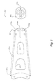
- FIG. 1 is an isometric bottom view of a fan configured in accordance with an embodiment of the present technology.
- FIG. 2A is an enlarged, partially-exploded isometric top view of a fan hub configured in accordance with an embodiment of the present technology
- FIG. 2B is an enlarged, cross-sectional view taken generally along line 2 B- 2 B in FIG. 2A illustrating a hub retention feature in more detail.
- FIG. 3 is an enlarged, exploded isometric view of the central hub assembly of FIG. 2A .
- FIG. 4 is partially exploded, top isometric view of a blade mounting structure configured in accordance with an embodiment of the present technology.
- FIG. 5A is a front view and FIG. 5B is a top view of the blade mounting structure of FIG. 4 , and FIG. 5C is a cross-sectional end view of a portion of the blade mounting structure of FIG. 5B taken along line 5 C- 5 C in FIG. 5B .
- FIG. 6 is a partially exploded isometric view of a blade mounting structure configured in accordance with another embodiment of the present technology.
- FIG. 7 is a top view of a spacer insert and a support member of the blade mounting structure of FIG. 6 .
- FIG. 8A is a top view of the blade mounting structure of FIG. 6
- FIGS. 8B and 8C are cross-sectional side and end views, respectively, taken along lines 8 B- 8 B and 8 C- 8 C in FIG. 8A , respectively.
- FIG. 9 is a partially exploded, top isometric view of a blade mounting structure configured in accordance with another embodiment of the present technology.
- FIG. 10A is an isometric top view of a central portion of a fan having a plurality of blade mounting structures configured in accordance with another embodiment of the present technology
- FIG. 10B is an enlarged, cross-sectional view taken generally along line 10 B- 10 B in FIG. 10A illustrating a hub retention feature in more detail.
- FIG. 1 is an isometric bottom view of a fan 100 configured in accordance with an embodiment of the present technology.
- the fan 100 is an HLVS fan attached to a ceiling 102 of a building by a mounting bracket 103 and a hanger 104 .
- the mounting bracket 103 is adjustable so that the fan 100 can be suspended from an angled ceiling, joist, beam, wall, etc. while remaining generally in parallel with the floor or ground (not shown).
- the vertical length of the hanger 104 can be selected so that the fan 100 hangs at a suitable height above the floor of the building.
- the fan 100 includes a drive unit mount 106 coupled to the hanger 104 .
- the drive unit mount 106 supports a drive unit 107 (e.g., an electric motor, engine, gear assembly or gearbox, etc.) that is operably coupled to a central fan hub 130 (“hub 130 ”) by a drive shaft (not visible in FIG. 1 ).
- a plurality of fan blades 140 e.g., five fan blades 140
- the fan blades 140 extend radially outward from the mounting structures 150 , and can have a length L from an inboard end portion 143 to a tip portion 144 of from about 3 ft. to about 14 ft.
- these blade lengths L can result in an outer diameter of the fan 100 of from about 6 ft. to about 30 ft. or more, such as from about 12 ft. to about 26 ft., or about 20 ft. to about 24 ft.
- the fan blades 140 can have other lengths and the fan 100 can have other outer diameters.
- the fan blades 140 can be formed from extruded aluminum or aluminum alloy, fabricated metal, or other suitably rigid and lightweight materials (e.g., a carbon fiber material) known in the art.
- the fan blades 140 can be made from a T6 temper aluminum alloy, such as 6061 or 6063 aluminum alloys.
- the individual fan blades 140 have an airfoil shape with a fixed angle of attack.
- the fan blades 140 can optionally include winglets 142 that enhance air flow at the outboard ends of the fan blades 140 .
- the fan blades 140 can include winglets described in U.S. patent application Ser. No. 13/302,507, filed Nov.
- the fan blades 140 can have a different shape and/or configuration, and/or a non-constant or changeable angle of attack.
- the fan blades 140 can have a flat profile rather than an airfoil shape.
- the fan 100 includes five fan blades in the illustrated embodiment, in other embodiments the fan 100 can include more or fewer fan blades (e.g., ten fan blades).
- the drive unit 107 rotates the fan blades 140 via the hub 130 about a central axis 105 at a rotational speed of, e.g., 10 to 100 rpm.
- a user can control the rotational speed and/or the direction of rotation using, for example, a wall-mounted control panel and/or a wireless controller coupled to the drive unit controller (not shown) of the drive unit 107 .
- the fan blades 140 can produce a moving volume of air, e.g., a column of air (not shown) in a generally downward and/or upward direction, depending on the direction of rotation of the fan blades 140 .
- FIG. 2A is an enlarged, partially-exploded isometric top view of the hub 130 configured in accordance with an embodiment of the present technology.
- the hub 130 is rotably coupled to the drive unit 107 ( FIG. 1 ) by a drive shaft 208 that extends through a first opening (not visible) in a mounting plate 210 of the drive unit mount 106 , and a second opening 214 in the hub 130 .
- the hub 130 is secured to the drive shaft 208 by a fitting 212 (e.g., an expansion coupling) that is installed from a bottom side 213 b of the hub 130 .
- a fitting 212 e.g., an expansion coupling
- the expansion coupling 212 includes, for example, a fenner nut assembly having an expandable member 215 a (e.g., an expandable nut) that wedges between the drive shaft 208 and the hub 130 and threadably engages a locking member 215 b (e.g., a bolt).
- the locking member 215 b engages the expandable member 215 a such that when installed, (i.e., when tightened), the locking member 215 b compresses the expandable member 215 a along its longitudinal axis. This, in turn, cause the expandable member 215 a to expand radially between the hub 130 and the drive shaft 208 and thereby secure the hub 130 to the drive shaft 208 .
- a retention member or ring 216 is attached to a top side 213 a of the hub 130 by a plurality of fasteners 217 a (e.g., hex-head bolts) that threadably engage corresponding locking features 217 b (e.g., lock nuts; FIG. 3 ) toward the bottom side 213 b of the hub 130 .
- the retention ring 216 includes an outward flange or outer lip 218 that extends at least partially around the second opening 214 .
- First and second retention members 220 a and 220 b are attached to the underside of the mounting plate 210 of the drive unit mount 106 .
- each of the retention members 220 includes a mounting portion 222 and an inward flange or inner lip 224 (e.g., a flange or other suitable retaining feature) attached to the mounting plate 210 by a plurality of fasteners 223 a (e.g., hex-head bolts) that threadably engage corresponding locking features 223 b (e.g., lock nuts) positioned on the opposite side of the mounting plate 210 .
- the mounting portion 222 positions the inner lip 224 so that it extends directly between the hub 130 and the outer lip 218 of the retention ring 216 and directly beneath the outer lip 218 .
- FIG. 2B is an enlarged, cross-sectional view taken generally along line 2 B- 2 B in FIG. 2A , and illustrating the relationship between the retention ring 216 and the second retention member 220 b in more detail.
- the retention ring 216 is vertically separated from the retention members 220 by a gap G so that the retention ring 216 is free to rotate above the inner lip 224 of the retention member 220 .
- the retention ring 216 is configured to engage the retention members 220 should the hub 130 ever disengage from the drive shaft 208 in use, such as if the expansion fitting 212 broke free from the drive shaft 208 during operation.
- the retention members 220 can also simplify maintenance and installation of the fan 100 because they can be installed after the hub 130 is attached to the drive shaft 208 .
- the individual retention members 220 can be slid into position on opposite sides of the retention ring 216 and fastened into place without having to disconnect the hub 130 from the drive shaft 208 .
- the retention ring 216 and the retention members 220 can also support the hub 130 during maintenance of the fan 100 .
- the retention ring 216 and the retention members 220 can hold the hub 130 when replacing the drive unit 107 and/or the drive shaft 208 .
- FIG. 3 is an enlarged, exploded isometric view of the hub 130 configured in accordance with an embodiment of the present technology.
- the hub 130 includes a first or upper hub plate 332 a separated from a second or lower hub plate 332 b (collectively “hub plates 332 ”) by a central spacer 333 and a plurality of outer spacers 336 .
- the central spacer 333 is securely sandwiched between the upper and lower hub plates 332 a and 332 b by the fasteners 217 a and the locking features 217 b .
- the upper hub plate 332 a has a plurality of first flanges 334 a that generally define a “star” pattern toward the outer periphery of the hub 130 .
- the lower hub plate 332 b has a plurality of corresponding second flanges 334 b generally aligned with the first flanges 334 a and spaced vertically therefrom by the outer spacers 336 .
- a plurality of threaded metal studs 337 e.g., two per outer spacer/flange combination align and extend through the outer spacers 336 and corresponding fastener holes 331 in the mating flanges 334 .
- the metal studs 337 are configured to secure the individual blade mounting structures 150 ( FIG. 1 ) to the hub plates 332 .
- the components of the hub 130 can be formed from a variety of suitable materials known in the art, including metallic materials, using techniques such as press-forming, machining, casting, etc.
- the hub plates 332 , the central spacer 333 , and outer spacers 336 can be made from T6 tempered aluminum alloys; and the retention ring 216 and the retention members 220 can be made from a suitable steel material (e.g., ASTM A36).
- the hub plates 332 have “star” shapes, in other embodiments the hub plates 332 can have different shapes, such as a round shape, pentagonal shape, etc.
- the hub 130 can include integrally formed components.
- the hub 130 can be a single fabricated part or unitary part (e.g. molding, casting, forging or the like), or portions of the hub 130 can be formed from a single material rather than two or more pieces fastened together.
- FIG. 4 is partially exploded isometric view of the blade mounting structure 150 configured in accordance with an embodiment of the present technology.
- the blade mounting structure 150 (which can also be referred to as, e.g., a blade strut, blade support structure, truss, or framework) includes a first or upper support member 452 a and a second or lower support member 452 b (collectively “support members 452 ”).
- the support members are flat and elongate members that extend between the hub 130 and the inboard end portion 143 of the fan blade 140 .
- the upper support member 452 a includes a proximal end portion 453 a attached to the hub 130 toward the top side 213 a by fasteners 454 a (e.g., lock nuts) threadably engaged with first end portions 335 a of the metal studs 337 .
- the lower support member 452 b similarly includes a proximal end portion 453 b attached to the hub 130 at the bottom side 213 b by locking features 454 b (e.g., lock nuts) threadably engaged with opposite second end portions 335 b of the metal studs 337 .
- the proximal end portion 453 a of the upper support member 452 a is attached to adjacent flanges 334 a of the upper hub plate 332 a and bridges therebetween, and the proximal end portion 453 b of the lower support member 452 b is similarly attached to the corresponding adjacent flanges 334 b of the lower hub plate 332 b.
- the blade mounting structure 150 further includes a third support member or strut 456 that couples the support members 452 to the inboard end portion 143 of the fan blade 140 .
- the strut 456 can include, for example, an elongate shaft (e.g., a tube, beam etc.).
- a first portion 457 a of the strut 456 is sandwiched between the support members 452 and attached thereto by a plurality of fasteners 458 b (e.g., Huck fastener pins) that are threadably engaged with radial locking features 458 a (e.g., Huck collars).
- a second portion 457 b of the strut 456 (shown in hidden lines) is inserted into a cavity through an opening 445 at the inboard end portion 143 .
- the second portion 457 b is secured to the fan blade 140 within the cavity by a plurality of fasteners 459 b (e.g., Huck fastener pins) that threadably engage corresponding locking features 459 a (e.g., Huck collars).
- the second portion 457 b of the strut 456 can be attached to an exterior portion of the fan blade 140 , rather than being inserted into a cavity of the fan blade 140 .
- FIG. 5A is a front view
- FIG. 5B is a top view of the blade mounting structure 150 attached to the fan blade 140 .
- the support members 452 carry the fan blade 140 such that the inboard end portion 143 of the fan blade 140 is spaced apart from the hub 130 ( FIG. 1 ) along the longitudinal axis of the fan blade 140 .
- the inboard end portion 143 can be offset from the outer periphery of the hub 130 by a distance D of from about, e.g., 6 inches to about 24 inches, or about 15 inches. In one embodiment, for example, the inboard end portion 143 can be offset from hub 130 by a distance D of about 15 inches.
- each of the support members 452 includes an angled portion 560 (identified individually as first and second angled portions 560 a and 560 b , respectively) and a non-angled portion 562 .
- the first angled portion 560 a extends generally downward from the proximal end portion 453 a toward the strut 456 .
- the second angled portion 560 b extends generally upward from the proximal end portion 453 b toward strut 456 .
- the first portion 457 a of the strut 456 is positioned between the support members 452
- the second portion 457 b of the strut 456 (shown in hidden lines) extends into the fan blade 140 along the longitudinal axis thereof.
- the strut 456 can have a length of from about 4 inches to about 18 inches, such as about 15 inches. In other embodiments, the strut 456 of the fan blade 140 can have other lengths, such as a quarter of the length of the fan blade 140 , half the length of the fan blade, the entire length of the fan blade, etc.
- each of the support members 452 has a tapered profile that narrows or tapers inwardly as it extends from the hub 130 to the inboard end portion 143 of the fan blade 140 .
- an outboard edge 563 of each of the support members 452 can abut against the inboard end portion 143 of the fan blade 140 . In other embodiments, however, the outboard edge 563 and the inboard end portion 143 can be spaced apart from each another.
- each of the support members 452 includes a cut-out or opening 564 generally medially disposed in the angled portions 560 .
- the opening 564 can reduce the overall weight of the blade mounting structure 150 , and can be configured to augment the vertical air flow profile of the fan 100 .
- certain shapes and/or sizes of the openings 564 can promote uptake of air toward the center of the fan 100 , i.e., when the fan blades 140 are producing a generally downward draft of air away from the center of the fan 100 .
- the support members 452 and the strut 456 can be formed, for example, from various suitable materials and methods, such as metals, e.g., sheet metal or metal castings, plastic molds or the like.
- the support members 452 can be laser-cut from sheet metal, such as high-strength, low-alloy steel (e.g., ASTM A572), and the strut 456 can be formed from aluminum alloy, such as T6 tempered aluminum alloy.
- the support members 452 are identical or at least have generally the same shape and are symmetric with one another in the vertical direction about the longitudinal axis of the fan blade 140 . In other embodiments, however, the support members 452 can have different shapes and/or be asymmetric.
- the flanges 334 of the hub 130 can carry the support members 452 such that they are asymmetric about the longitudinal axis of the blade mounting structure 150 .
- FIG. 5C is a cross-sectional end view of a portion of the fan blade 140 and the strut 456 taken along line 5 C- 5 C in FIG. 5B .
- the fan blade 140 includes a web 548 extending generally vertically along the longitudinal axis of the fan blade and separating a first leading edge or cavity 549 a from a second trailing edge or cavity 549 b .
- the web 548 can be a stiffening structure that is integrally formed with or attached (e.g., welded) to an outer wall or skin 541 of the fan blade 140 .
- the web 548 can also form a contoured pocket that firmly receives the snugly fitted strut 456 in the leading edge cavity 549 a.
- the strut 456 has a contoured surface 571 that at least partially conforms to the shape and profile (e.g., curvature) of the leading edge cavity 549 a to facility a snug or close fit between the strut 456 and the fan blade 140 .
- the strut 456 can be hollow or partially hollow and include a stiffening web 573 extending along the longitudinal axis thereof.
- the strut 456 can have other shapes and/or profiles.
- the strut 456 can have an outer edge that does not conform or does not substantially conform to the leading edge cavity 549 a.
- Fan blades in conventional HVLS fans abut against the hub and attach to the hub with a small hub connector, such as a metal stub attached to or integrated with the hub.
- a small hub connector such as a metal stub attached to or integrated with the hub.
- the long fan blades can apply relatively large loads, such as torsional loads to the hub connector, which can lead to premature wear or to damage of the hub connector.
- fan blades can apply a substantial twisting force along their longitudinal axis during operation, which can add further stress to conventional hub connectors.
- a singular hub connector can be vulnerable to single point failure mechanisms due to the concentration of stress and other loads at this singular connection.
- Blade mounting structures configured in accordance with various embodiments of the present technology, such as the blade mounting structure 150 , can address these and other limitations of conventional hub connectors by providing a relatively strong and stiff connection between the fan blades and the hub to reduce or eliminate the effects of coning, twisting, torsional, and/or other forces.
- the blade mounting structures can reduce or alleviate stress at the junctions with the fasteners that attach the blade mounting structure 150 to the hub 130 and the inboard end portion 143 of the fan blade 140 .
- FIG. 6 is partially exploded isometric view of a blade mounting structure 650 configured in accordance with another embodiment of the present technology.
- the blade mounting structure 650 can include features generally similar in structure and function to those of the blade mounting structure 150 described in detail above with reference to FIGS. 1-5C .
- the blade mounting structure 650 can include upper and lower support members 652 a and 652 b (collectively “support members 652 ”) that are each mounted to adjacent flanges 334 of the upper and lower hub plates 332 a and 332 b , respectively, Similar to the support members 452 of FIG. 4 , each of the support members 652 can include formed openings 664 to, e.g., reduce weight or enhance performance.
- support members 652 can include formed openings 664 to, e.g., reduce weight or enhance performance.
- a spacer insert 665 is sandwiched between distal end portions 651 of the support members 652 .
- the end portion 651 are inserted into the inboard end portion 143 of the fan blade 140 .
- the support members 652 are then attached to the fan blade 140 by a plurality of fasteners 667 (e.g., rivets).
- FIG. 7 is a top view of the spacer insert 665 and the support members 652 of FIG. 6 .
- FIG. 8A is a top view of the blade mounting structure 650
- FIGS. 8B and 8C are cross-sectional side and end views, respectively, taken along lines 8 B- 8 B and 8 C- 8 C in FIG. 8A , respectively.
- the distal end portions 651 of the support members 652 include a longitudinal slot 770 a and the spacer insert 665 includes a longitudinal slot 770 b that receive the web 548 of the fan blade 140 ( FIG. 5C ) when the distal end portions 651 are inserted into the inboard end portion 143 of the fan blade 140 ( FIG. 8C ).
- a first side 775 a of the distal end portion 651 extends into the leading edge cavity 549 a ( FIGS. 5C and 8C ), and a second side 775 b of the distal end portion 651 extends into the trailing edge cavity 549 b .
- the distal end portions 651 and the spacer insert 665 conform to the curved contours of the leading edge and trailing edge cavities 549 a and 549 b to facilitate a snug or close fit within the fan blade 140 .
- the spacer insert 665 can press the support members 652 against the inner surfaces of the leading edge and trailing edge cavities 549 a and 549 b .
- the distal end portions 651 and/or the spacer insert 665 can have different shapes, sizes, and/or contours.
- the spacer insert 665 can have a longitudinal length S ( FIG. 8B ) from about 1 inch to about 10 inches, such as about 5 inches.
- the spacer insert 665 can be formed, for example, from a suitable metallic, plastic, or other material.
- the spacer insert 665 can include an extruded aluminum alloy having an at least partially hollow cavity (not shown).
- the spacer insert 665 can include a molded plastic or cast metal.
- an epoxy or other suitable fill material can be used in lieu of the spacer insert 665 to fill the void between the distal end portions 651 of the support members 650 within the leading edge cavity 549 a and/or the trailing edge cavity 549 b.
- FIG. 9 is partially exploded isometric view of a blade mounting structure 950 configured in accordance with another embodiment of the present technology.
- the blade mounting structure 950 can include features generally similar in structure and function to those of the blade mounting structures 150 and 650 described in detail above with reference to FIGS. 1-8C .
- the blade mounting structure 950 can include a spacer insert 665 coupled to distal end portions 651 of upper and lower support members 952 a and 952 b (collectively “support members 952 ”).
- the upper support member 952 a can include a first spacer portion 974 a integrally formed in a medial portion therein, and the lower support member 952 b can similarly include a second spacer portion 974 b integrally formed in a medial portion therein.
- the first and second spacer portions 974 a and 974 b can extend generally toward each other and can be attached together by a fastener 976 (e.g., a rivet).
- the first and second spacer portions 974 a and 974 b can strengthen or enhance the rigidity of the blade mounting structure 950 .
- the spacer portions 974 a and 974 b can be positioned differently, such as more proximate to the hub 130 .
- the blade mounting structure 950 can include additional sets of spacer portions.
- the blade mounting structure 950 can include two or three sets of spacer portions, with each set positioned along the longitudinal axis of the blade mounting structure 950 .
- FIG. 10A is an isometric top view of a central portion of a fan 1000 having a plurality of blade mounting structures 1050 coupled to a central hub 1030 in accordance with another embodiment of the present technology.
- the hub 1030 and the blade mounting structures 1050 can include features generally similar in structure and function to those of the hub 130 and the blade mounting structures 150 , 650 , and 950 described in detail above with reference to FIGS. 1-9 .
- the blade mounting structure 1050 can include upper and lower support members 1052 a and 1052 b having proximal end portions 1053 that attach adjacent to the hub plates 332 .
- each of the upper support members 1052 a includes a raised inward flange or inner lip 1082 on the proximal end portion 1053 .
- a retention member or ring 1083 includes a mounting portion 1085 coupled to an underside of the mounting plate 210 via a plurality of fasteners 1090 a (e.g., hex-head bolts) that threadably engage corresponding locking features 1090 b (e.g., locking nuts) positioned on the opposite side of the mounting plate 210 .
- the retention ring 1083 also includes an outward flange or outer lip 1084 that extends at least partially around the second opening 214 .
- FIG. 10B is an enlarged, cross-sectional view taken generally along line 10 B- 10 B in FIG. 10A , and illustrates the relationship between the retention ring 1083 and the inner lip 1082 of the upper support member 1052 a in more detail. Similar to the retention ring 216 and the retention members 220 described above with reference to FIGS. 2A and 2B , the inner lip 1082 of the upper support member 1052 a is configured to engage the outer lip 1084 of the retention ring 1083 should the hub 1030 ever disengage from the drive shaft 208 ( FIG. 2A ) in use.
- the inner lip 1082 of the upper support member 1052 a would fall onto the outer lip 1084 of the retention ring 1083 (as shown by arrow F), and thus would prevent the hub 1030 from falling from the mounting plate 210 .
- the inner lip 1082 of the upper support member 1052 a is integrally formed with the upper support member 1052 , and thus simplify manufacturing because it can reduce the overall number of parts of the fan 100 .
- the inner lip can be a separate piece that is attached to the upper support member 1052 with, e.g., a weld, fasteners, etc.
- a remotely positioned drive unit or engine can rotate the drive shaft 208 ( FIG. 2A ) with a system of one or more belts and/or pulleys.
- the support members 452 , 652 , 952 , and/or 1052 described above with reference to FIGS. 1-10B can include more than two members and/or have different sizes, shapes, and/or profiles (e.g., non-tapered profiles).
- fasteners may be illustrated for coupling components of the fan together (e.g., Huck fastener pins and collars, hex-head bolts, screws, rivets, etc.), in other embodiments, other types of fasteners known in the art can be used.
- components can be attached to one another by other attachment techniques in addition to and/or in lieu of fasteners, such as welding, adhesives, etc.
- fasteners such as welding, adhesives, etc.
Landscapes
- Engineering & Computer Science (AREA)
- Mechanical Engineering (AREA)
- General Engineering & Computer Science (AREA)
- Structures Of Non-Positive Displacement Pumps (AREA)
Abstract
Description
Claims (27)
Priority Applications (1)
| Application Number | Priority Date | Filing Date | Title |
|---|---|---|---|
| US14/166,663 US9874214B2 (en) | 2014-01-28 | 2014-01-28 | Fan with fan blade mounting structure |
Applications Claiming Priority (1)
| Application Number | Priority Date | Filing Date | Title |
|---|---|---|---|
| US14/166,663 US9874214B2 (en) | 2014-01-28 | 2014-01-28 | Fan with fan blade mounting structure |
Publications (2)
| Publication Number | Publication Date |
|---|---|
| US20150211532A1 US20150211532A1 (en) | 2015-07-30 |
| US9874214B2 true US9874214B2 (en) | 2018-01-23 |
Family
ID=53678616
Family Applications (1)
| Application Number | Title | Priority Date | Filing Date |
|---|---|---|---|
| US14/166,663 Active 2036-08-15 US9874214B2 (en) | 2014-01-28 | 2014-01-28 | Fan with fan blade mounting structure |
Country Status (1)
| Country | Link |
|---|---|
| US (1) | US9874214B2 (en) |
Cited By (12)
| Publication number | Priority date | Publication date | Assignee | Title |
|---|---|---|---|---|
| US20180256932A1 (en) * | 2017-03-09 | 2018-09-13 | Great Fitness Industrial Co., Ltd. | Exercise bicycle configured to provide fan-based resistance and fan wheel thereof |
| US20190120246A1 (en) * | 2017-04-21 | 2019-04-25 | Evapco, Inc. | Cooling towers axial fan in a hollowed disc/ring configuration |
| USD857877S1 (en) * | 2018-03-12 | 2019-08-27 | Sunonwealth Electric Machine Industry Co., Ltd. | End plate of a blade of a ceiling fan |
| US10518874B2 (en) * | 2016-05-25 | 2019-12-31 | Airbus Helicopters Deutschland GmbH | Multi-blade rotor for a rotary wing aircraft |
| USD956949S1 (en) * | 2019-04-19 | 2022-07-05 | Delta T, Llc | Fan |
| USD965135S1 (en) * | 2019-12-17 | 2022-09-27 | Delta T, Llc | Winglet for fan |
| US11527937B2 (en) | 2019-01-04 | 2022-12-13 | Sunonwealth Electric Machine Industry Co., Ltd. | Motor and ceiling fan including the motor |
| IT202100023681A1 (en) * | 2021-09-14 | 2023-03-14 | Gigola & Riccardi S P A | Room ventilation device |
| US20230094150A1 (en) * | 2020-03-10 | 2023-03-30 | Cofimco S.R.L. | Blade System for Fans for Industrial Use |
| USD994105S1 (en) * | 2023-05-25 | 2023-08-01 | Foshan Ruideng Lighting Co., Ltd. | Ceiling fan with light |
| USD994106S1 (en) * | 2023-05-25 | 2023-08-01 | Foshan Ruideng Lighting Co., Ltd. | Ceiling fan with light |
| USD1005475S1 (en) * | 2019-03-04 | 2023-11-21 | Delta T, Llc | Ceiling fan motor housing |
Families Citing this family (12)
| Publication number | Priority date | Publication date | Assignee | Title |
|---|---|---|---|---|
| TWI680040B (en) * | 2014-09-17 | 2019-12-21 | 美商法伯沃克斯分解股份有限公司 | Multi-component robotic hub mounting plate to facilitate hub removal |
| US9726192B2 (en) | 2015-03-31 | 2017-08-08 | Assa Abloy Entrance Systems Ab | Fan blades and associated blade tips |
| US11674526B2 (en) | 2016-01-22 | 2023-06-13 | Hunter Fan Company | Ceiling fan having a dual redundant motor mounting assembly |
| CN112943651B (en) * | 2015-12-14 | 2023-06-23 | 亨特风扇公司 | ceiling fan |
| EP3612731A4 (en) * | 2017-04-21 | 2020-12-30 | Evapco, Inc. | Cooling tower axial fan in a hollowed disc/ring configuration |
| US11168698B2 (en) * | 2018-08-27 | 2021-11-09 | Hunter Fan Company | Ceiling fan |
| US11473488B2 (en) * | 2020-12-15 | 2022-10-18 | Caterpillar Inc. | Engine fan adapter systems and methods |
| US11377998B1 (en) * | 2020-12-15 | 2022-07-05 | Caterpillar Inc. | Fan adapter for an engine |
| USD1010802S1 (en) * | 2021-02-09 | 2024-01-09 | Hunter Fan Company | Telescopic down rod assembly |
| US20220282736A1 (en) * | 2021-03-08 | 2022-09-08 | Macroair Technologies, Inc. | System and kit for attachment to a support structure of a control panel for a high-volume low speed fan |
| USD1001265S1 (en) * | 2022-03-29 | 2023-10-10 | Hunter Fan Company | Telescopic down rod assembly |
| US20240263640A1 (en) * | 2023-02-02 | 2024-08-08 | Phillip S. Eggers | High volume low speed air-circulation fan |
Citations (122)
| Publication number | Priority date | Publication date | Assignee | Title |
|---|---|---|---|---|
| US11629A (en) | 1854-08-29 | Improved governor for | ||
| US871729A (en) | 1906-06-14 | 1907-11-19 | William C Mcchord Jr | Electric fan. |
| US1041913A (en) | 1909-12-06 | 1912-10-22 | James R Tyson | Aerial propeller. |
| GB100134A (en) | 1915-03-01 | 1917-03-01 | Bbc Brown Boveri & Cie | Improvements in the Manufacture of Blades for Steam and Gas Turbines. |
| US1379439A (en) | 1919-09-22 | 1921-05-24 | Bastian Bros Company | Wind-wheel |
| US1614186A (en) | 1920-10-27 | 1927-01-11 | Westinghouse Electric & Mfg Co | Tip for propellers |
| US2014032A (en) | 1934-10-24 | 1935-09-10 | Robbins & Myers | An and the like |
| US2952320A (en) | 1956-04-30 | 1960-09-13 | Bensen Aircraft Corp | Airfoil |
| GB946794A (en) | 1961-03-06 | 1964-01-15 | Colchester Woods | Improvements in and relating to axial flow fans or compressors |
| US3524712A (en) | 1966-05-17 | 1970-08-18 | Rolls Royce | Compressor blade for a gas turbine engine |
| US3721507A (en) | 1971-09-22 | 1973-03-20 | United Aircraft Corp | Blade for high speed helicopter |
| US4093402A (en) | 1974-06-10 | 1978-06-06 | Theodoor Van Holten | Propeller or a set of wings for a wind mill |
| US4174924A (en) | 1975-10-21 | 1979-11-20 | Wallace Murray Corporation | Sheet metal fan assembly |
| GB2050530A (en) | 1979-05-12 | 1981-01-07 | Papst Motoren Kg | Impeller Blades |
| US4248572A (en) | 1978-12-11 | 1981-02-03 | United Technologies Corporation | Helicopter blade |
| US4324530A (en) | 1980-01-21 | 1982-04-13 | United Technologies Corp. | Helicopter blade with a tip having a selected combination of sweep, taper and anhedral to improve hover efficiency |
| US4334828A (en) | 1980-01-21 | 1982-06-15 | United Technologies Corporation | Helicopter blade with a tip having a selected combination of sweep, taper and anhedral to improve hover efficiency |
| US4634341A (en) * | 1984-12-20 | 1987-01-06 | Hudson Products Corporation | Axial flow fans |
| US4662823A (en) | 1985-10-28 | 1987-05-05 | Cooke Frank L | Air turbulence blades for ceiling fans |
| US4722608A (en) | 1985-07-30 | 1988-02-02 | General Signal Corp. | Mixing apparatus |
| US4744728A (en) | 1986-09-03 | 1988-05-17 | United Technologies Corporation | Helicopter blade airfoil |
| GB2198190A (en) | 1986-11-28 | 1988-06-08 | Frank L Cook | Air turbulence blades for ceiling fans |
| DE3819145A1 (en) | 1988-06-04 | 1989-12-14 | Albrecht George Prof D Fischer | Aerodynamically active end plates for aircraft-wing and propeller-blade tips |
| US4968216A (en) | 1984-10-12 | 1990-11-06 | The Boeing Company | Two-stage fluid driven turbine |
| US4975022A (en) | 1988-07-05 | 1990-12-04 | Westland Helicopter Limited | Helicopter rotor blades |
| US5213476A (en) | 1990-07-02 | 1993-05-25 | Hudson Products Corporation | Fan blade |
| US5226783A (en) | 1990-07-30 | 1993-07-13 | Usui Kokusai Sangyo Kaisha Ltd. | Axial flow fan with centrifugal elements |
| US5320494A (en) | 1992-12-22 | 1994-06-14 | United Technologies Corporation | Helicopter rotor blade having a replaceable anhedral tip |
| US5348253A (en) | 1993-02-01 | 1994-09-20 | Gratzer Louis B | Blended winglet |
| US5564901A (en) | 1993-12-14 | 1996-10-15 | The Moore Company | Low noise fan |
| US5601409A (en) | 1996-01-16 | 1997-02-11 | Huang; Yung C. | Fan blade for ceiling fans |
| US5725355A (en) | 1996-12-10 | 1998-03-10 | General Electric Company | Adhesive bonded fan blade |
| US5785282A (en) | 1995-08-18 | 1998-07-28 | Sikorsky Aircraft Corporation | Half-plow vortex generators for rotorcraft blades for reducing blade-vortex interaction noise |
| US5823480A (en) | 1993-04-05 | 1998-10-20 | La Roche; Ulrich | Wing with a wing grid as the end section |
| US5860788A (en) | 1996-06-14 | 1999-01-19 | Shell Electric Mfg. (Holdings) Co. Ltd. | Low drag fan assembly |
| US5885059A (en) | 1996-12-23 | 1999-03-23 | Sikorsky Aircraft Corporation | Composite tip cap assembly for a helicopter main rotor blade |
| US5927948A (en) | 1996-04-30 | 1999-07-27 | Gkn Westland Helicopters Limited | Propeller |
| US5992793A (en) | 1996-01-04 | 1999-11-30 | Gkn Westland Helicopters Limited | Aerofoil |
| US6039541A (en) | 1998-04-07 | 2000-03-21 | University Of Central Florida | High efficiency ceiling fan |
| US6106235A (en) | 1999-03-24 | 2000-08-22 | Caframo Ltd. | Co-molded fan vane |
| WO2000049342A2 (en) | 1999-02-19 | 2000-08-24 | Mechanization Systems Company, Inc. | Low speed cooling fan |
| US6109874A (en) | 1998-02-17 | 2000-08-29 | Steiner; Gregory A. | Portable fan device |
| US6161797A (en) | 1996-11-25 | 2000-12-19 | Dugan Air Technologies, Inc. | Method and apparatus for reducing airplane noise |
| US6315522B1 (en) | 1999-02-23 | 2001-11-13 | Advanced Technology Institute Of Commuter-Helicopter, Ltd. | Helicopter blade aerofoil and helicopter blade |
| US6334705B1 (en) | 1998-10-01 | 2002-01-01 | General Signal Corporation | Fluid mixing impellers with shear generating venturi |
| US6431498B1 (en) | 2000-06-30 | 2002-08-13 | Philip Watts | Scalloped wing leading edge |
| US20020155807A1 (en) | 2001-03-12 | 2002-10-24 | Moor Matthew C. | Device for controlling an air-moving apparatus upon activation of a smoke detector |
| US20020182071A1 (en) | 2001-05-29 | 2002-12-05 | Belady Christian L. | Enhanced performance fan with the use of winglets |
| US6565320B1 (en) | 2000-11-13 | 2003-05-20 | Borgwarner, Inc. | Molded cooling fan |
| US20030095864A1 (en) | 2001-11-19 | 2003-05-22 | Borislav Ivanovic | Fan with reduced noise |
| US20030095874A1 (en) | 2001-11-22 | 2003-05-22 | Shinji Tagami | Swash plate for swash plate-type variable displacement compressor |
| US20040063571A1 (en) | 2000-11-09 | 2004-04-01 | Yoo-Kyoung Kim | Prepolymerization method of alpha-olefin |
| US6719533B2 (en) | 2002-07-11 | 2004-04-13 | Hunter Fan Company | High efficiency ceiling fan |
| US20040131470A1 (en) | 2003-01-06 | 2004-07-08 | Walter Boyd | Cooling fan with reinforced blade |
| US6884034B1 (en) | 1998-04-07 | 2005-04-26 | University Of Central Florida | Enhancements to high efficiency ceiling fan |
| US6976829B2 (en) | 2003-07-16 | 2005-12-20 | Sikorsky Aircraft Corporation | Rotor blade tip section |
| EP1619391A2 (en) | 2004-07-21 | 2006-01-25 | Delta T Corporation | Fan blade |
| WO2006022812A1 (en) | 2004-07-21 | 2006-03-02 | Delta T Corporation | Fan blades and modifications |
| US20060104812A1 (en) | 2004-11-18 | 2006-05-18 | Sikorsky Aircraft Corporation | Mission replaceable rotor blade tip section |
| US20060187750A1 (en) | 2002-03-01 | 2006-08-24 | Victor Aldrich | Rotary blending apparatus and system |
| US7128536B2 (en) * | 2003-06-10 | 2006-10-31 | Rolls-Royce Plc | Damped aerofoil structure |
| US7284960B2 (en) | 2004-07-21 | 2007-10-23 | Delta T Corporation | Fan blades |
| US20080008596A1 (en) | 2004-07-21 | 2008-01-10 | Aynsley Richard M | Fan Blades |
| US20080014090A1 (en) | 2004-07-21 | 2008-01-17 | Aynsley Richard M | Cuffed fan blade modifications |
| US20080193294A1 (en) | 2007-02-08 | 2008-08-14 | Rite-Hite Holding Corporation | Industrial ceiling fan |
| US20080213097A1 (en) | 2007-03-01 | 2008-09-04 | Oleson Richard A | Angled airfoil extension for fan blade |
| USD587799S1 (en) | 2008-08-15 | 2009-03-03 | Delta T Corporation | Winglet for a fan blade |
| US20090072108A1 (en) | 2007-09-17 | 2009-03-19 | Delta T Corporation | Ceiling Fan with Angled Mounting |
| US20090081045A1 (en) | 2007-09-26 | 2009-03-26 | Scherer Paul T | Aerodynamic Interface Component for Fan Blade |
| WO2009049052A1 (en) | 2007-10-10 | 2009-04-16 | Delta T Corporation | Ceiling fan with concentric stationary tube and power-down features |
| US20090162197A1 (en) | 2007-12-19 | 2009-06-25 | Delta T Corporation | Automatic Control System and Method to Minimize Oscillation in Ceiling Fans |
| US20090178815A1 (en) | 2008-01-15 | 2009-07-16 | Anderson Daniel M | Fire safety systems for buildings with overhead fans |
| US20090208333A1 (en) | 2007-10-10 | 2009-08-20 | Smith J Carey | Ceiling Fan System with Brushless Motor |
| US20090253364A1 (en) | 2008-04-07 | 2009-10-08 | Mark Henry | Rechargeable fire containment and smoke extraction system |
| USD607988S1 (en) | 2009-04-29 | 2010-01-12 | Delta T Corporation | Ceiling fan |
| US20100034651A1 (en) | 2008-08-11 | 2010-02-11 | Wiegel Aaron J | Ceiling fans with low solidity ratio |
| US20100034664A1 (en) | 2008-08-11 | 2010-02-11 | Wiegel Aaron J | Sprinkler-compatible ceiling fans |
| US20100104461A1 (en) | 2008-10-29 | 2010-04-29 | Smith J Carey | Multi-Part Modular Airfoil Section and Method of Attachment Between Parts |
| US20100247316A1 (en) | 2009-03-25 | 2010-09-30 | Aynsley Richard M | High Efficiency Ducted Fan |
| US20100278637A1 (en) | 2009-05-04 | 2010-11-04 | Oleson Richard A | Ceiling Fan with Variable Blade Pitch and Variable Speed Control |
| US20100291858A1 (en) | 2008-02-04 | 2010-11-18 | Delta T Corporation | Automatic control system for ceiling fan based on temperature differentials |
| USD631536S1 (en) | 2009-05-21 | 2011-01-25 | Rite-Hite Holding Corporation | Fan blade |
| USD635237S1 (en) | 2010-03-05 | 2011-03-29 | Delta T Corporation | Fan with ground support |
| WO2011041220A1 (en) | 2009-10-02 | 2011-04-07 | Delta T Corporation | Air fence for fan blade |
| US7955055B1 (en) | 2006-04-14 | 2011-06-07 | Macroair Technologies, Inc. | Safety retaining system for large industrial fan |
| US20110156002A1 (en) | 2008-09-04 | 2011-06-30 | Leatherdale Catherine A | Light source having light blocking components |
| USD641075S1 (en) | 2010-03-05 | 2011-07-05 | Delta T Corporation | Fan with ground support and winglets |
| US20110262278A1 (en) | 2010-04-22 | 2011-10-27 | Fizer Richard W | Fan blade retention system |
| WO2011138626A1 (en) | 2010-05-03 | 2011-11-10 | Haiku Design SDN. BHD. | A ceiling fan |
| US8066480B2 (en) | 2007-11-09 | 2011-11-29 | AirMotion Sciences, Inc. | High volume low speed fan |
| USD650893S1 (en) | 2009-06-09 | 2011-12-20 | Delta T Corporation | Upright fan |
| EP2397783A1 (en) * | 2010-06-21 | 2011-12-21 | Cmp Impianti S.R.L. | Device for Ventilating a Room |
| US20120128501A1 (en) | 2010-11-23 | 2012-05-24 | 4Front Engineered Solutions, Inc. | Fan blade tips |
| USD672868S1 (en) | 2012-02-09 | 2012-12-18 | Delta T Corporation | Winglet for fan blade |
| USD676953S1 (en) | 2011-02-28 | 2013-02-26 | Delta T Corporation | Fan with shroud |
| US20130189109A1 (en) | 2012-01-20 | 2013-07-25 | Delta T Corporation | Thin airfoil ceiling fan blade |
| US20130189104A1 (en) * | 2012-01-25 | 2013-07-25 | Delta T Corporation | Fan with resilient hub |
| USD690409S1 (en) | 2012-03-02 | 2013-09-24 | Delta T Corporation | Ceiling fan |
| US20130251522A1 (en) | 2012-03-20 | 2013-09-26 | Delta T Corporation | Ball and socket fan mount |
| USD692120S1 (en) | 2012-03-02 | 2013-10-22 | Delta T Corporation | Ceiling fan with light |
| US8579588B1 (en) * | 2009-04-29 | 2013-11-12 | Macroair Technologies, Inc. | Hub assembly for a large cooling fan |
| US8646177B2 (en) | 2010-12-07 | 2014-02-11 | General Electric Company | Method and apparatus for mounting a rotor blade on a wind turbine |
| WO2014071046A1 (en) | 2012-10-31 | 2014-05-08 | Delta T Corporation | Integrated thermal comfort control system utilizing circulating fans |
| WO2014070747A1 (en) | 2012-10-30 | 2014-05-08 | Delta T Corporation | Fan mounting system |
| USD705976S1 (en) | 2013-08-20 | 2014-05-27 | Delta T Corporation | Lighting fixture |
| USD705975S1 (en) | 2013-08-20 | 2014-05-27 | Delta T Corporation | Lighting fixture |
| US8770949B2 (en) | 2008-09-04 | 2014-07-08 | Delta T Corporation | Ceiling fan |
| US8842000B2 (en) | 2012-07-17 | 2014-09-23 | 4Front Engineered Solutions, Inc. | Fire control systems |
| USD717935S1 (en) | 2013-06-17 | 2014-11-18 | Delta T Corporation | Ceiling fan |
| USD717936S1 (en) | 2014-02-27 | 2014-11-18 | Delta T Corporation | Blade tip |
| US20140348649A1 (en) | 2013-05-24 | 2014-11-27 | Delta T Corporation | Ceiling fan with moisture protection features |
| US20150037164A1 (en) | 2012-04-03 | 2015-02-05 | Delta Corporation | Airfoil for fan blade |
| USD723678S1 (en) | 2013-06-17 | 2015-03-03 | Delta T Corporation | Winglet for a ceiling fan |
| WO2015031322A1 (en) | 2013-08-26 | 2015-03-05 | Delta T Corporation | Tunable luminaire and related methods to control light output |
| US9011099B2 (en) * | 2012-06-19 | 2015-04-21 | Skyblade Fan Company | High volume low speed fan |
| US20150147188A1 (en) | 2013-11-25 | 2015-05-28 | Macroair Technologies, Inc. | High Volume Low Speed Fan Using Direct Drive Transverse Flux Motor |
| USD732657S1 (en) | 2014-02-27 | 2015-06-23 | Delta T Corporation | Winglet |
| WO2015142871A1 (en) | 2014-03-17 | 2015-09-24 | Delta T Corporation | Fan with remote temperature sensor and mounting arrangement |
| WO2015153604A1 (en) | 2014-03-31 | 2015-10-08 | Delta T Corporation | Fan with learning mode |
| WO2015168127A1 (en) | 2014-04-28 | 2015-11-05 | Delta T Corporation | Environmental condition control based on sensed conditions and related methods |
| US9192027B1 (en) | 2013-12-02 | 2015-11-17 | Delta T Corporation | Luminaire and related methods to control light output dependent upon temperature |
| US20160290357A1 (en) | 2015-03-31 | 2016-10-06 | Assa Abloy Entrance Systems Ab | Fan blades and associated blade tips |
-
2014
- 2014-01-28 US US14/166,663 patent/US9874214B2/en active Active
Patent Citations (180)
| Publication number | Priority date | Publication date | Assignee | Title |
|---|---|---|---|---|
| US11629A (en) | 1854-08-29 | Improved governor for | ||
| US871729A (en) | 1906-06-14 | 1907-11-19 | William C Mcchord Jr | Electric fan. |
| US1041913A (en) | 1909-12-06 | 1912-10-22 | James R Tyson | Aerial propeller. |
| GB100134A (en) | 1915-03-01 | 1917-03-01 | Bbc Brown Boveri & Cie | Improvements in the Manufacture of Blades for Steam and Gas Turbines. |
| US1379439A (en) | 1919-09-22 | 1921-05-24 | Bastian Bros Company | Wind-wheel |
| US1614186A (en) | 1920-10-27 | 1927-01-11 | Westinghouse Electric & Mfg Co | Tip for propellers |
| US2014032A (en) | 1934-10-24 | 1935-09-10 | Robbins & Myers | An and the like |
| US2952320A (en) | 1956-04-30 | 1960-09-13 | Bensen Aircraft Corp | Airfoil |
| GB946794A (en) | 1961-03-06 | 1964-01-15 | Colchester Woods | Improvements in and relating to axial flow fans or compressors |
| US3524712A (en) | 1966-05-17 | 1970-08-18 | Rolls Royce | Compressor blade for a gas turbine engine |
| US3721507A (en) | 1971-09-22 | 1973-03-20 | United Aircraft Corp | Blade for high speed helicopter |
| US4093402A (en) | 1974-06-10 | 1978-06-06 | Theodoor Van Holten | Propeller or a set of wings for a wind mill |
| US4174924A (en) | 1975-10-21 | 1979-11-20 | Wallace Murray Corporation | Sheet metal fan assembly |
| US4248572A (en) | 1978-12-11 | 1981-02-03 | United Technologies Corporation | Helicopter blade |
| GB2050530A (en) | 1979-05-12 | 1981-01-07 | Papst Motoren Kg | Impeller Blades |
| US4324530A (en) | 1980-01-21 | 1982-04-13 | United Technologies Corp. | Helicopter blade with a tip having a selected combination of sweep, taper and anhedral to improve hover efficiency |
| US4334828A (en) | 1980-01-21 | 1982-06-15 | United Technologies Corporation | Helicopter blade with a tip having a selected combination of sweep, taper and anhedral to improve hover efficiency |
| US4968216A (en) | 1984-10-12 | 1990-11-06 | The Boeing Company | Two-stage fluid driven turbine |
| US4634341A (en) * | 1984-12-20 | 1987-01-06 | Hudson Products Corporation | Axial flow fans |
| US4722608A (en) | 1985-07-30 | 1988-02-02 | General Signal Corp. | Mixing apparatus |
| US4662823A (en) | 1985-10-28 | 1987-05-05 | Cooke Frank L | Air turbulence blades for ceiling fans |
| US4744728A (en) | 1986-09-03 | 1988-05-17 | United Technologies Corporation | Helicopter blade airfoil |
| GB2198190A (en) | 1986-11-28 | 1988-06-08 | Frank L Cook | Air turbulence blades for ceiling fans |
| DE3819145A1 (en) | 1988-06-04 | 1989-12-14 | Albrecht George Prof D Fischer | Aerodynamically active end plates for aircraft-wing and propeller-blade tips |
| US4975022A (en) | 1988-07-05 | 1990-12-04 | Westland Helicopter Limited | Helicopter rotor blades |
| US5213476A (en) | 1990-07-02 | 1993-05-25 | Hudson Products Corporation | Fan blade |
| US5226783A (en) | 1990-07-30 | 1993-07-13 | Usui Kokusai Sangyo Kaisha Ltd. | Axial flow fan with centrifugal elements |
| US5320494A (en) | 1992-12-22 | 1994-06-14 | United Technologies Corporation | Helicopter rotor blade having a replaceable anhedral tip |
| US5348253A (en) | 1993-02-01 | 1994-09-20 | Gratzer Louis B | Blended winglet |
| US5823480A (en) | 1993-04-05 | 1998-10-20 | La Roche; Ulrich | Wing with a wing grid as the end section |
| US5564901A (en) | 1993-12-14 | 1996-10-15 | The Moore Company | Low noise fan |
| US5785282A (en) | 1995-08-18 | 1998-07-28 | Sikorsky Aircraft Corporation | Half-plow vortex generators for rotorcraft blades for reducing blade-vortex interaction noise |
| US5992793A (en) | 1996-01-04 | 1999-11-30 | Gkn Westland Helicopters Limited | Aerofoil |
| US5601409A (en) | 1996-01-16 | 1997-02-11 | Huang; Yung C. | Fan blade for ceiling fans |
| US5927948A (en) | 1996-04-30 | 1999-07-27 | Gkn Westland Helicopters Limited | Propeller |
| US5860788A (en) | 1996-06-14 | 1999-01-19 | Shell Electric Mfg. (Holdings) Co. Ltd. | Low drag fan assembly |
| US6161797A (en) | 1996-11-25 | 2000-12-19 | Dugan Air Technologies, Inc. | Method and apparatus for reducing airplane noise |
| US5725355A (en) | 1996-12-10 | 1998-03-10 | General Electric Company | Adhesive bonded fan blade |
| US5885059A (en) | 1996-12-23 | 1999-03-23 | Sikorsky Aircraft Corporation | Composite tip cap assembly for a helicopter main rotor blade |
| US6109874A (en) | 1998-02-17 | 2000-08-29 | Steiner; Gregory A. | Portable fan device |
| US6039541A (en) | 1998-04-07 | 2000-03-21 | University Of Central Florida | High efficiency ceiling fan |
| US6884034B1 (en) | 1998-04-07 | 2005-04-26 | University Of Central Florida | Enhancements to high efficiency ceiling fan |
| US6334705B1 (en) | 1998-10-01 | 2002-01-01 | General Signal Corporation | Fluid mixing impellers with shear generating venturi |
| US6244821B1 (en) | 1999-02-19 | 2001-06-12 | Mechanization Systems Company, Inc. | Low speed cooling fan |
| WO2000049342A2 (en) | 1999-02-19 | 2000-08-24 | Mechanization Systems Company, Inc. | Low speed cooling fan |
| US20020001521A1 (en) | 1999-02-19 | 2002-01-03 | Boyd Walter K. | Low speed cooling fan |
| EP1173359A2 (en) | 1999-02-19 | 2002-01-23 | Mechanization Systems Company, Inc. | Low speed cooling fan |
| US6589016B2 (en) * | 1999-02-19 | 2003-07-08 | Mechanization Systems Co., Inc. | Low speed cooling fan |
| US6817835B2 (en) | 1999-02-19 | 2004-11-16 | Mechanization Systems Company, Inc. | Low speed cooling fan |
| US20040084544A1 (en) | 1999-02-19 | 2004-05-06 | Boyd Walter K. | Low speed cooling fan |
| US6315522B1 (en) | 1999-02-23 | 2001-11-13 | Advanced Technology Institute Of Commuter-Helicopter, Ltd. | Helicopter blade aerofoil and helicopter blade |
| US6106235A (en) | 1999-03-24 | 2000-08-22 | Caframo Ltd. | Co-molded fan vane |
| US6431498B1 (en) | 2000-06-30 | 2002-08-13 | Philip Watts | Scalloped wing leading edge |
| US20040063571A1 (en) | 2000-11-09 | 2004-04-01 | Yoo-Kyoung Kim | Prepolymerization method of alpha-olefin |
| US6565320B1 (en) | 2000-11-13 | 2003-05-20 | Borgwarner, Inc. | Molded cooling fan |
| US20020155807A1 (en) | 2001-03-12 | 2002-10-24 | Moor Matthew C. | Device for controlling an air-moving apparatus upon activation of a smoke detector |
| US6517315B2 (en) | 2001-05-29 | 2003-02-11 | Hewlett-Packard Company | Enhanced performance fan with the use of winglets |
| US20020182071A1 (en) | 2001-05-29 | 2002-12-05 | Belady Christian L. | Enhanced performance fan with the use of winglets |
| US6776578B2 (en) | 2001-05-29 | 2004-08-17 | Hewlett-Packard Development Company, L.P. | Winglet-enhanced fan |
| US20030095864A1 (en) | 2001-11-19 | 2003-05-22 | Borislav Ivanovic | Fan with reduced noise |
| US20030095874A1 (en) | 2001-11-22 | 2003-05-22 | Shinji Tagami | Swash plate for swash plate-type variable displacement compressor |
| US20060187750A1 (en) | 2002-03-01 | 2006-08-24 | Victor Aldrich | Rotary blending apparatus and system |
| US6719533B2 (en) | 2002-07-11 | 2004-04-13 | Hunter Fan Company | High efficiency ceiling fan |
| US20040131470A1 (en) | 2003-01-06 | 2004-07-08 | Walter Boyd | Cooling fan with reinforced blade |
| US6939108B2 (en) | 2003-01-06 | 2005-09-06 | Mechanization Systems Company, Inc. | Cooling fan with reinforced blade |
| US7128536B2 (en) * | 2003-06-10 | 2006-10-31 | Rolls-Royce Plc | Damped aerofoil structure |
| US6976829B2 (en) | 2003-07-16 | 2005-12-20 | Sikorsky Aircraft Corporation | Rotor blade tip section |
| US7654798B2 (en) | 2004-07-21 | 2010-02-02 | Delta T Corporation | Fan blade modifications |
| WO2006022812A1 (en) | 2004-07-21 | 2006-03-02 | Delta T Corporation | Fan blades and modifications |
| EP1619391A2 (en) | 2004-07-21 | 2006-01-25 | Delta T Corporation | Fan blade |
| US8075273B2 (en) | 2004-07-21 | 2011-12-13 | Delta T Corporation | Fan blade modifications |
| US7252478B2 (en) | 2004-07-21 | 2007-08-07 | Delta T Corporation | Fan blade modifications |
| US7284960B2 (en) | 2004-07-21 | 2007-10-23 | Delta T Corporation | Fan blades |
| US20080008596A1 (en) | 2004-07-21 | 2008-01-10 | Aynsley Richard M | Fan Blades |
| US20080014090A1 (en) | 2004-07-21 | 2008-01-17 | Aynsley Richard M | Cuffed fan blade modifications |
| US20080014092A1 (en) | 2004-07-21 | 2008-01-17 | Delta T Corporation | Fan blade modifications |
| US8079823B2 (en) | 2004-07-21 | 2011-12-20 | Delta T Corporation | Fan blades |
| US20100104445A1 (en) | 2004-07-21 | 2010-04-29 | Delta T Corporation | Fan Blade Modifications |
| US7934907B2 (en) | 2004-07-21 | 2011-05-03 | Delta T Corporation | Cuffed fan blade modifications |
| US20060104812A1 (en) | 2004-11-18 | 2006-05-18 | Sikorsky Aircraft Corporation | Mission replaceable rotor blade tip section |
| US7246998B2 (en) | 2004-11-18 | 2007-07-24 | Sikorsky Aircraft Corporation | Mission replaceable rotor blade tip section |
| US20140093385A1 (en) | 2006-04-14 | 2014-04-03 | Macroair Technologies, Inc. | Safety retaining system for large industrial fan |
| US7955055B1 (en) | 2006-04-14 | 2011-06-07 | Macroair Technologies, Inc. | Safety retaining system for large industrial fan |
| US8956124B2 (en) | 2006-04-14 | 2015-02-17 | Macroair Technologies, Inc. | Safety retaining system for large industrial fan |
| US7726945B2 (en) * | 2007-02-08 | 2010-06-01 | Rite-Hite Holding Corporation | Industrial ceiling fan |
| WO2008097735A1 (en) | 2007-02-08 | 2008-08-14 | Rite-Hite Holding Corporation | Industrial ceiling fan |
| US20080193294A1 (en) | 2007-02-08 | 2008-08-14 | Rite-Hite Holding Corporation | Industrial ceiling fan |
| US8162613B2 (en) | 2007-03-01 | 2012-04-24 | Delta T Corporation | Angled airfoil extension for fan blade |
| US20080213097A1 (en) | 2007-03-01 | 2008-09-04 | Oleson Richard A | Angled airfoil extension for fan blade |
| WO2009011933A1 (en) | 2007-03-01 | 2009-01-22 | Delta T Corporation | Angled airfoil extension for fan blade |
| US20120177500A1 (en) | 2007-03-01 | 2012-07-12 | Delta T Corporation | Angled airfoil extension for fan blade |
| US8821126B2 (en) | 2007-03-01 | 2014-09-02 | Delta T Corporation | Angled airfoil extension for fan blade |
| US20090072108A1 (en) | 2007-09-17 | 2009-03-19 | Delta T Corporation | Ceiling Fan with Angled Mounting |
| US8152453B2 (en) | 2007-09-17 | 2012-04-10 | Delta T Corporation | Ceiling fan with angled mounting |
| WO2009038988A1 (en) | 2007-09-17 | 2009-03-26 | Delta T Corporation | Ceiling fan with angled mounting |
| US8147204B2 (en) | 2007-09-26 | 2012-04-03 | Delta T Corporation | Aerodynamic interface component for fan blade |
| US20090081045A1 (en) | 2007-09-26 | 2009-03-26 | Scherer Paul T | Aerodynamic Interface Component for Fan Blade |
| US20090097975A1 (en) | 2007-10-10 | 2009-04-16 | Richard Michael Aynsley | Ceiling Fan with Concentric Stationary Tube and Power-Down Features |
| WO2009049052A1 (en) | 2007-10-10 | 2009-04-16 | Delta T Corporation | Ceiling fan with concentric stationary tube and power-down features |
| US8147182B2 (en) | 2007-10-10 | 2012-04-03 | Delta T Corporation | Ceiling fan with concentric stationary tube and power-down features |
| US8876468B2 (en) | 2007-10-10 | 2014-11-04 | Delta T Corporation | Ceiling fan with concentric stationary tube and power-down features |
| US20120177509A1 (en) | 2007-10-10 | 2012-07-12 | Delta T Corporation | Ceiling fan with concentric stationary tube and power-down features |
| US20090208333A1 (en) | 2007-10-10 | 2009-08-20 | Smith J Carey | Ceiling Fan System with Brushless Motor |
| US8672649B2 (en) | 2007-10-10 | 2014-03-18 | Delta T Corporation | Ceiling fan system with brushless motor |
| US20140023507A1 (en) | 2007-10-10 | 2014-01-23 | Moog Inc. | Ceiling fan system with brushless motor |
| US8066480B2 (en) | 2007-11-09 | 2011-11-29 | AirMotion Sciences, Inc. | High volume low speed fan |
| US20090162197A1 (en) | 2007-12-19 | 2009-06-25 | Delta T Corporation | Automatic Control System and Method to Minimize Oscillation in Ceiling Fans |
| US8123479B2 (en) | 2007-12-19 | 2012-02-28 | Delta T Corporation | Method to minimize oscillation in ceiling fans |
| US7658232B2 (en) | 2008-01-15 | 2010-02-09 | Rite-Hite Holding Corporation | Fire safety systems for buildings with overhead fans |
| US20090178815A1 (en) | 2008-01-15 | 2009-07-16 | Anderson Daniel M | Fire safety systems for buildings with overhead fans |
| EP2271408A1 (en) | 2008-01-15 | 2011-01-12 | Rite-Hite Holding Corporation | Fire safety systems for buildings with overhead fans |
| WO2009091443A1 (en) | 2008-01-15 | 2009-07-23 | Rite-Hite Holding Corporation | Fire safety systems for buildings with overhead fans |
| US20150086383A1 (en) | 2008-02-04 | 2015-03-26 | Delta T Corporation | Automatic control system for ceiling fan based on temperature differentials |
| US8900041B2 (en) | 2008-02-04 | 2014-12-02 | Delta T Corporation | Automatic control system for ceiling fan based on temperature differentials |
| US20100291858A1 (en) | 2008-02-04 | 2010-11-18 | Delta T Corporation | Automatic control system for ceiling fan based on temperature differentials |
| US20090253364A1 (en) | 2008-04-07 | 2009-10-08 | Mark Henry | Rechargeable fire containment and smoke extraction system |
| US8622712B2 (en) | 2008-08-11 | 2014-01-07 | Rite-Hite Holding Corporation | Sprinkler-compatible ceiling fans |
| WO2010019472A1 (en) | 2008-08-11 | 2010-02-18 | Rite-Hite Holding Corporation | Sprinkler-compatible ceiling fans |
| US8142156B2 (en) | 2008-08-11 | 2012-03-27 | Rite-Hite Holding Corporation | Ceiling fans with low solidity ratio |
| US20100034664A1 (en) | 2008-08-11 | 2010-02-11 | Wiegel Aaron J | Sprinkler-compatible ceiling fans |
| US20100034651A1 (en) | 2008-08-11 | 2010-02-11 | Wiegel Aaron J | Ceiling fans with low solidity ratio |
| USD642674S1 (en) | 2008-08-15 | 2011-08-02 | Delta T Corporation | Winglet for a fan blade |
| USD587799S1 (en) | 2008-08-15 | 2009-03-03 | Delta T Corporation | Winglet for a fan blade |
| US8770949B2 (en) | 2008-09-04 | 2014-07-08 | Delta T Corporation | Ceiling fan |
| US20110156002A1 (en) | 2008-09-04 | 2011-06-30 | Leatherdale Catherine A | Light source having light blocking components |
| US20100104461A1 (en) | 2008-10-29 | 2010-04-29 | Smith J Carey | Multi-Part Modular Airfoil Section and Method of Attachment Between Parts |
| US20140072431A1 (en) | 2008-10-29 | 2014-03-13 | Delta T Corporation | Multi-Part Modular Airfoil Section and Method of Attachment Between Parts |
| US8529212B2 (en) | 2008-10-29 | 2013-09-10 | Delta T Corporation | Multi-part modular airfoil section and method of attachment between parts |
| US20100247316A1 (en) | 2009-03-25 | 2010-09-30 | Aynsley Richard M | High Efficiency Ducted Fan |
| US8579588B1 (en) * | 2009-04-29 | 2013-11-12 | Macroair Technologies, Inc. | Hub assembly for a large cooling fan |
| USD607988S1 (en) | 2009-04-29 | 2010-01-12 | Delta T Corporation | Ceiling fan |
| US8721305B2 (en) | 2009-05-04 | 2014-05-13 | Delta T Corporation | Ceiling fan with variable blade pitch and variable speed control |
| US20100278637A1 (en) | 2009-05-04 | 2010-11-04 | Oleson Richard A | Ceiling Fan with Variable Blade Pitch and Variable Speed Control |
| US20150023802A1 (en) | 2009-05-04 | 2015-01-22 | Richard A. Oleson | Ceiling Fan with Variable Blade Pitch and Variable Speed Control |
| USD631536S1 (en) | 2009-05-21 | 2011-01-25 | Rite-Hite Holding Corporation | Fan blade |
| USD650893S1 (en) | 2009-06-09 | 2011-12-20 | Delta T Corporation | Upright fan |
| US8753081B2 (en) | 2009-10-02 | 2014-06-17 | Delta T Corporation | Air fence for fan blade |
| WO2011041220A1 (en) | 2009-10-02 | 2011-04-07 | Delta T Corporation | Air fence for fan blade |
| US20140286779A1 (en) | 2009-10-02 | 2014-09-25 | Delta T Corporation | Air fence for fan blade |
| US20110081246A1 (en) | 2009-10-02 | 2011-04-07 | Aynsley Richard M | Air fence for fan blade |
| USD641075S1 (en) | 2010-03-05 | 2011-07-05 | Delta T Corporation | Fan with ground support and winglets |
| USD635237S1 (en) | 2010-03-05 | 2011-03-29 | Delta T Corporation | Fan with ground support |
| US20110262278A1 (en) | 2010-04-22 | 2011-10-27 | Fizer Richard W | Fan blade retention system |
| US20150078902A1 (en) | 2010-04-22 | 2015-03-19 | Delta T Corporation | Fan blade retention system |
| US8770937B2 (en) * | 2010-04-22 | 2014-07-08 | Delta T Corporation | Fan blade retention system |
| WO2011133419A1 (en) | 2010-04-22 | 2011-10-27 | Delta T Corporation | Fan blade retention system |
| WO2011138626A1 (en) | 2010-05-03 | 2011-11-10 | Haiku Design SDN. BHD. | A ceiling fan |
| EP2397783A1 (en) * | 2010-06-21 | 2011-12-21 | Cmp Impianti S.R.L. | Device for Ventilating a Room |
| US20120128501A1 (en) | 2010-11-23 | 2012-05-24 | 4Front Engineered Solutions, Inc. | Fan blade tips |
| US8646177B2 (en) | 2010-12-07 | 2014-02-11 | General Electric Company | Method and apparatus for mounting a rotor blade on a wind turbine |
| USD676953S1 (en) | 2011-02-28 | 2013-02-26 | Delta T Corporation | Fan with shroud |
| US20130189109A1 (en) | 2012-01-20 | 2013-07-25 | Delta T Corporation | Thin airfoil ceiling fan blade |
| WO2013109711A1 (en) | 2012-01-20 | 2013-07-25 | Delta T Corporation | Thin airfoil ceiling fan blade |
| WO2013112721A1 (en) | 2012-01-25 | 2013-08-01 | Delta T Corporation | Fan with resilient hub |
| US20130189104A1 (en) * | 2012-01-25 | 2013-07-25 | Delta T Corporation | Fan with resilient hub |
| USD672868S1 (en) | 2012-02-09 | 2012-12-18 | Delta T Corporation | Winglet for fan blade |
| USD692120S1 (en) | 2012-03-02 | 2013-10-22 | Delta T Corporation | Ceiling fan with light |
| USD690409S1 (en) | 2012-03-02 | 2013-09-24 | Delta T Corporation | Ceiling fan |
| US20130251522A1 (en) | 2012-03-20 | 2013-09-26 | Delta T Corporation | Ball and socket fan mount |
| US20150037164A1 (en) | 2012-04-03 | 2015-02-05 | Delta Corporation | Airfoil for fan blade |
| US9011099B2 (en) * | 2012-06-19 | 2015-04-21 | Skyblade Fan Company | High volume low speed fan |
| US8842000B2 (en) | 2012-07-17 | 2014-09-23 | 4Front Engineered Solutions, Inc. | Fire control systems |
| US20150260199A1 (en) | 2012-10-30 | 2015-09-17 | Delta T Corporation | Fan mounting system |
| WO2014070747A1 (en) | 2012-10-30 | 2014-05-08 | Delta T Corporation | Fan mounting system |
| WO2014071046A1 (en) | 2012-10-31 | 2014-05-08 | Delta T Corporation | Integrated thermal comfort control system utilizing circulating fans |
| WO2014190285A1 (en) | 2013-05-24 | 2014-11-27 | Delta T Corporation | Ceiling fan with moisture protection features |
| US20140348649A1 (en) | 2013-05-24 | 2014-11-27 | Delta T Corporation | Ceiling fan with moisture protection features |
| USD717935S1 (en) | 2013-06-17 | 2014-11-18 | Delta T Corporation | Ceiling fan |
| USD723678S1 (en) | 2013-06-17 | 2015-03-03 | Delta T Corporation | Winglet for a ceiling fan |
| USD705975S1 (en) | 2013-08-20 | 2014-05-27 | Delta T Corporation | Lighting fixture |
| USD705976S1 (en) | 2013-08-20 | 2014-05-27 | Delta T Corporation | Lighting fixture |
| WO2015031322A1 (en) | 2013-08-26 | 2015-03-05 | Delta T Corporation | Tunable luminaire and related methods to control light output |
| US20150147188A1 (en) | 2013-11-25 | 2015-05-28 | Macroair Technologies, Inc. | High Volume Low Speed Fan Using Direct Drive Transverse Flux Motor |
| US9192027B1 (en) | 2013-12-02 | 2015-11-17 | Delta T Corporation | Luminaire and related methods to control light output dependent upon temperature |
| USD717936S1 (en) | 2014-02-27 | 2014-11-18 | Delta T Corporation | Blade tip |
| USD732657S1 (en) | 2014-02-27 | 2015-06-23 | Delta T Corporation | Winglet |
| WO2015142871A1 (en) | 2014-03-17 | 2015-09-24 | Delta T Corporation | Fan with remote temperature sensor and mounting arrangement |
| WO2015153604A1 (en) | 2014-03-31 | 2015-10-08 | Delta T Corporation | Fan with learning mode |
| WO2015168127A1 (en) | 2014-04-28 | 2015-11-05 | Delta T Corporation | Environmental condition control based on sensed conditions and related methods |
| US20160290357A1 (en) | 2015-03-31 | 2016-10-06 | Assa Abloy Entrance Systems Ab | Fan blades and associated blade tips |
Non-Patent Citations (33)
| Title |
|---|
| "The Intelligent Approach to Commercial / Industrial Ceiling Fans," Technical Guide, Commercial Industrial & Special Application Ceiling Fans, Leading Edge, A Marley Engineered Products Brand, Leading Edge 1999, 32 pages. |
| 747-400, Screenshot from http://www.boeing.com/commercial/747family/pf/pf—exterior.html; printed on Jul. 30, 2012, 1 page. |
| Advanced Blended Winglets, page last updated Feb. 6, 2004, The 737 Information Site, http://www.b7s7.org.uk Chris Brady 1999, 9 pages. |
| Airmotion Sciences, Inc., AirMotion™ AltAir™ eBrochure, 2010, 20 pages. |
| Airmotion Sciences, Inc., AirMotion™ Big Smart Fans™ 12-ft, Specifications Sheet, 2012, 1 page. |
| Airmotion Sciences, Inc., AirMotion™ Big Smart Fans™ 15-ft, Specifications Sheet, 2012, 1 page. |
| Airmotion Sciences, Inc., AirMotion™ Big Smart Fans™ 9-ft, Specifications Sheet, 2012, 1 page. |
| Airmotion Sciences, Inc., AirMotion™ Big Smart Fans™ for Agricultural Facilities, flyer, 2 pages. |
| Airmotion Sciences, Inc., What Is Heat DeStratification, and How AirMotion™ Big Smart Fans™ Help Reduce Heating costs, 2010, 1 page. |
| AirMotion™ AltAir™ The next Generation High Volume-Low Speed (HVLS) Fans, User Manual, © AirMotion Sciencies, Inc. 2010, 10 pages. |
| Big Ass Fans Installation Guide Powerfoil X, Oct. 2009, 2 pages. |
| Boeing 747-400 Twin-Aisle Jet Airliner, USA Screenshot from http://www.aerospacetechnology.com/projects/747/7473.html, printed on Jul. 30, 2012, 1 page. |
| Dairy Notes; University of California Cooperative Extension (May 1999), 5 pages. |
| Fairbank, "A Large Paddle Fan for Livestock Cooling" American Society of Agricultural Engineers, Jun. 1989, 16 pages. |
| Fan Brochure, Rite-Hite Fans, HVLS FANS, Date PDF Created: Aug. 31, 2010; 12 pages. |
| General Exterior Arrangement 737, Screenshot from http://www.boeing.com/commercial/737family/pf/pf—exterior.html, printed on Jul. 30, 2012, 1 page. |
| Image: Winglet and nav light arp.jpg, Screenshot from http://en.wikipedia.org/wiki/Image:Winglet—and—nav—light—arp.jpg; printed on Aug. 11, 2008. |
| Jain et al., "Experimental Investigation of the Flow Field of a Ceiling Fan," ASME Heat Transfer/Fluids Engineering Summer Conference, Paper No. HT-FED-2004-56226 (Jul. 2004) Abstract Only, 1 page. |
| KC-135A in flight—closeup of winglet with attached tufts, Screenshot from http://www.dfrc.nasa.gov/gallery/Photo/KC-135/Small/EC79-11481.jpg; Dated: 1979, 1 page. |
| KC-135A in flight-wing let study, EC79-11314, Screenshot from http://www.dfrc.nasa.gov/gallery/Photo/KC-135/Small/EC79-11314; Dated: 1979, 1 page. |
| KC-135A in flight-wing let study, EC79-11484, Screenshot from http://www.dfrc.nasa.gov/gallery/Photo/KC-135/Small/EC79-11484; Dated: 1979, 1 page. |
| Montoya, L.C.; KC-135 Winglet Flight Results, NASA Dryden Flight Research Center, pp. 145-156, 12 pages. |
| NASA Dryden Technology Facts—Winglets, Screenshot from http://www.nasa.gov/centers/dryden/about/Organizations/Technology/Facts/TF-2004-15-D; printed on Jul. 30, 2012, 1 page. |
| Next-Generation 737 Production Winglets, © Boeing, Jun. 5, 2004 snapshot of http://www.boeing.com/commercial/737family/pf/pf—winglets.html through waybackmachine Internet Archive. |
| Rite Hite Fan Commander Touch Screen; Date PDF created: Aug. 27, 2010; 2 pages. |
| Rite Hite Fans Revolution Installation and Owner's Manual, Jul. 2010, 2 pages. |
| Screenshots from www.b737.org.uk, relating to winglets, printed Jul. 2012, 11 pages. |
| U.S. Appl. No. 60/892,339, filed Mar. 1, 2007, 8 pages. |
| U.S. Appl. No. 60/972,890, filed Sep. 17, 2007, 8 pages. |
| U.S. Appl. No. 60/975,230, filed Sep. 26, 2007, 11 pages. |
| U.S. Appl. No. 60/978,860, filed Oct. 10, 2007, 15 pages. |
| Winglet Detail; screenshot from http://upload.wikimedia.org/wikipedia/commons/5/53/Wingletdetail.jpg; printed on Aug. 11, 2008. |
| Wingtip Device; screenshot from http://en.wikipedia.org/wiki/Wingtip—device; printed on Aug. 11, 2008. |
Cited By (15)
| Publication number | Priority date | Publication date | Assignee | Title |
|---|---|---|---|---|
| US10518874B2 (en) * | 2016-05-25 | 2019-12-31 | Airbus Helicopters Deutschland GmbH | Multi-blade rotor for a rotary wing aircraft |
| US10300321B2 (en) * | 2017-03-09 | 2019-05-28 | Great Fitness Industrial Co., Ltd. | Exercise bicycle configured to provide fan-based resistance and fan wheel thereof |
| US20180256932A1 (en) * | 2017-03-09 | 2018-09-13 | Great Fitness Industrial Co., Ltd. | Exercise bicycle configured to provide fan-based resistance and fan wheel thereof |
| US20190120246A1 (en) * | 2017-04-21 | 2019-04-25 | Evapco, Inc. | Cooling towers axial fan in a hollowed disc/ring configuration |
| US10808717B2 (en) * | 2017-04-21 | 2020-10-20 | Evapco, Inc. | Cooling towers axial fan in a hollowed disc/ring configuration |
| USD857877S1 (en) * | 2018-03-12 | 2019-08-27 | Sunonwealth Electric Machine Industry Co., Ltd. | End plate of a blade of a ceiling fan |
| US11527937B2 (en) | 2019-01-04 | 2022-12-13 | Sunonwealth Electric Machine Industry Co., Ltd. | Motor and ceiling fan including the motor |
| USD1005475S1 (en) * | 2019-03-04 | 2023-11-21 | Delta T, Llc | Ceiling fan motor housing |
| USD956949S1 (en) * | 2019-04-19 | 2022-07-05 | Delta T, Llc | Fan |
| USD965135S1 (en) * | 2019-12-17 | 2022-09-27 | Delta T, Llc | Winglet for fan |
| US20230094150A1 (en) * | 2020-03-10 | 2023-03-30 | Cofimco S.R.L. | Blade System for Fans for Industrial Use |
| US12092121B2 (en) * | 2020-03-10 | 2024-09-17 | Cofimco S.R.L. | Blade system for fans for industrial use |
| IT202100023681A1 (en) * | 2021-09-14 | 2023-03-14 | Gigola & Riccardi S P A | Room ventilation device |
| USD994105S1 (en) * | 2023-05-25 | 2023-08-01 | Foshan Ruideng Lighting Co., Ltd. | Ceiling fan with light |
| USD994106S1 (en) * | 2023-05-25 | 2023-08-01 | Foshan Ruideng Lighting Co., Ltd. | Ceiling fan with light |
Also Published As
| Publication number | Publication date |
|---|---|
| US20150211532A1 (en) | 2015-07-30 |
Similar Documents
| Publication | Publication Date | Title |
|---|---|---|
| US9874214B2 (en) | Fan with fan blade mounting structure | |
| US8579588B1 (en) | Hub assembly for a large cooling fan | |
| US9011099B2 (en) | High volume low speed fan | |
| CN100504036C (en) | Cooling fan with reinforced blade | |
| US9523371B2 (en) | Fan with resilient hub | |
| CN102135110B (en) | Centrifugal impeller | |
| US8123485B2 (en) | Rotor hub of a wind energy plant | |
| US10422314B2 (en) | Spiral blade unit and wind generator and blade connector for the unit | |
| US9926943B2 (en) | Axial blower | |
| US6499948B1 (en) | Shroud and axial fan therefor | |
| JP6882294B2 (en) | Tunnel wind turbine with horizontal rotor axis | |
| CN201358955Y (en) | Propeller-type axial-flow impeller | |
| CN102927047B (en) | Large axial-flow impeller | |
| TWI334899B (en) | ||
| CN2634159Y (en) | Novel transformer cooling fan | |
| CN202883478U (en) | Large-scale axial flow impeller | |
| CN202756300U (en) | Installation structure of axial flow fan blade | |
| KR101747598B1 (en) | Method for assembling guide vane of axial flow blower or axial fan | |
| CN102362075B (en) | Reinforcing element for use with ventilator hub | |
| CN203453117U (en) | Backward centrifugal wind wheel | |
| CN109707644A (en) | Axis galvanic electricity machine and air processor with it | |
| CN102297159B (en) | Axial impeller with vanes and hubs in composite hinge | |
| CN210003559U (en) | axial-flow fan blade and air conditioner with same | |
| CN215719645U (en) | Bidirectional ventilator for grain depot | |
| CN202301175U (en) | Axial flow impeller formed by compositely hinging blade with wheel hub |
Legal Events
| Date | Code | Title | Description |
|---|---|---|---|
| AS | Assignment |
Owner name: 4FRONT ENGINEERED SOLUTIONS, INC., TEXAS Free format text: ASSIGNMENT OF ASSIGNORS INTEREST;ASSIGNOR:WHITLEY, L. BLAKE;REEL/FRAME:032109/0550 Effective date: 20140128 |
|
| AS | Assignment |
Owner name: 4FRONT ENGINEERED SOLUTIONS, INC., TEXAS Free format text: CORRECTIVE ASSIGNMENT TO CORRECT THE STATE OF INCORPORATION OF THE ASSIGNEE PREVIOUSLY RECORDED ON REEL 032109 FRAME 0550. ASSIGNOR(S) HEREBY CONFIRMS THE ASSIGNEE IS A CORPORATION OF WISCONSIN;ASSIGNOR:WHITLEY, L. BLAKE;REEL/FRAME:035727/0794 Effective date: 20140128 |
|
| STCF | Information on status: patent grant |
Free format text: PATENTED CASE |
|
| MAFP | Maintenance fee payment |
Free format text: PAYMENT OF MAINTENANCE FEE, 4TH YEAR, LARGE ENTITY (ORIGINAL EVENT CODE: M1551); ENTITY STATUS OF PATENT OWNER: LARGE ENTITY Year of fee payment: 4 |
|
| MAFP | Maintenance fee payment |
Free format text: PAYMENT OF MAINTENANCE FEE, 8TH YEAR, LARGE ENTITY (ORIGINAL EVENT CODE: M1552); ENTITY STATUS OF PATENT OWNER: LARGE ENTITY Year of fee payment: 8 |