US987419A - Circular pleasure-swing. - Google Patents
Circular pleasure-swing. Download PDFInfo
- Publication number
- US987419A US987419A US58216810A US1910582168A US987419A US 987419 A US987419 A US 987419A US 58216810 A US58216810 A US 58216810A US 1910582168 A US1910582168 A US 1910582168A US 987419 A US987419 A US 987419A
- Authority
- US
- United States
- Prior art keywords
- cars
- turret
- drums
- mast
- frame
- Prior art date
- Legal status (The legal status is an assumption and is not a legal conclusion. Google has not performed a legal analysis and makes no representation as to the accuracy of the status listed.)
- Expired - Lifetime
Links
- 230000033001 locomotion Effects 0.000 description 4
- 238000004804 winding Methods 0.000 description 4
- 230000000694 effects Effects 0.000 description 2
- 230000001105 regulatory effect Effects 0.000 description 2
- 230000000153 supplemental effect Effects 0.000 description 2
- 241000239290 Araneae Species 0.000 description 1
- 238000010276 construction Methods 0.000 description 1
- 230000009975 flexible effect Effects 0.000 description 1
Images


Classifications
-
- A—HUMAN NECESSITIES
- A63—SPORTS; GAMES; AMUSEMENTS
- A63G—MERRY-GO-ROUNDS; SWINGS; ROCKING-HORSES; CHUTES; SWITCHBACKS; SIMILAR DEVICES FOR PUBLIC AMUSEMENT
- A63G1/00—Roundabouts
- A63G1/28—Roundabouts with centrifugally-swingable suspended seats
Definitions
- My invention relates to a circular pleas ure swing and particularly contemplates the provision of a novel structure comprising broadly a stationary structure having a rotating turret carrying a plurality of cars suspended therefrom and rotatable therewith, together with means carried within the stationary structure for raising and lowering said cars during their rotation.
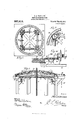
- Figure 1 is a perspective view of the com plete swing constructed according to my invention
- Fig. 2 is a detail plan view of the car raising and lowering mechanism
- Fig. 3 is an enlarged detail plan view of a portion thereof, broken away
- Fig. 4 is an enlarged detail elevation, partly in section
- Fig. 5 is an enlarged perspective view of a portion of the raising and lowering mechanism, partly in section and parts thereof being removed
- Fig. 6 is a plan view of the turret
- Fig. 7 is a side elevation of one of the cars
- Fig. 8 is an enlarged partial elevation of the turret
- Fig. 9 is a detail elevation partly in section illustrating a modified form of mechanism for raising and lowering the cars.
- I provide a stationary upright frame 1 tapering toward its upper end and provided in its length with spaced brace frames 2, on the upper one of which at the top of said frame 1 is mounted a rotating turret comprising an annulus 3 supported by a plurality of rollers 4 mounted upon the upper brace frame 2 to roll thereon.
- the annulus 3 carries a plurality of radial outwardly extending arms 5, each two of said arms being designed to support one of cars A.
- B v through from an engine room or the like B v is a rotating mast 6 connected adjacent its upper end to a circular plate 7 formed integral through the annulus 3 and carrying secure thereto at its extreme upper end a plurality of radially extending brace arms 8 extending downwardly therefrom and connected to the radial arms intermediate their ends to brace the same.
- the cars A are suspended from their respective arms 5 by ropes 9 extending over pulleys mounted in openings in the said arms 5 and in the brace arms 8 and downwardly through openings in the circular plate 7 of the annulus 3.
- the mast 6 is'adapted to be driven by a suitable motor arranged in the engine room B, to ro-- tate the turret carrying the cars A around in a circular path therewith.
- the ropes 9 by which the cars A are suspended extend downwardly within the frame 1 in pairs and are, in operation, wound about drums 10 mounted at right angles to one another upon a supporting frame 11 secured upon and extending around the rotating mast 6..
- the supporting frame 11 may be either in the form of a spider as shown in Fig. 2, or the same may be in the form of a circular ring as shown in Fig. 5, said frame being provided with rollers 12 mounted below the same and adapted to engage upon a track 13 formed within a supplemental stationary frame formed within the mounted frame 1.
- Each of the drums 10 about which the ropes 9 are wound are mounted upon shafts 14 arranged from brackets 15 extending from the frame 11 and provided thereon with a beveled gear 16.
- Each of the shafts 14 carries two of said drums 10, thus winding or unwinding simultaneously upon the two ropes 9 carrying one of the cars A.
- a pinion 17 having a beveled gear 18 formed integral therewith upon its upper face and in engagement with the beveled gear 16 of each of the shafts 14.
- a free moving annular ring 20 having inner and outer rack faces, said inner rack face being engaged by each of the pinions 17 of the drum operating mechanism.
- a single pinion 21 mounted to engage the outer rack face of the annular ring 20 and provided with a depending shaft 22 driven from its lower end from the electric motor or the like within the engine room B at a different speed of rotation from that of the vertical mast 6.
- the cars A are initially disposed near the lower end of the supporting frame or tower 1 so that passengers may enter therein.
- the engine or motor is then started and the mast 6 set rotating.
- the turret is accordingly rotated carrying with it the cars A.
- the shaft 22 may now remain stationary, whereby the ring 20 remains stationary, which results in the rotation of the drums 10 for raising the cars A by winding the cables 9 about said drums.
- the engine or motor for actuating shaft 22 may now be started, and the pinion 21 set in motion to effect the rotation of the ring 20. If this ring is driven at the same speed as the supporting frame 11, it is obvious that the drums 10 will remain stationary and hence the elevation of the cars A stopped.
- the speed at which I cars A are elevated may be regulated and said cars even stopped in their elevation while the mast 6 is being continuously rotated at the same speed. If the shaft 22 is rotated sufiiciently to cause the ring 20 to ro tate faster than the supporting frame 11, the rotation of the drums 10 will be reversed and the cars A lowered. It is obvious that if the ring 20 is being rotated at a slower speed than the rotation of the supporting frame 11, whereby the cars A are being elevated, upon the stopping and reversing of the engine or motor which drives the mast 6, the supporting frame 11 will be rotated in a reverse direction to rotate the drums 10 for lowering the cars A.
- the cars A are elevated when the mast 6 is rotated in one direction, and lowered when the mast is rotated in a reverse direction.
- each of the shafts lat upon which the ropes 9 are wound are provided with worm gears 23 engaged and rotated by a worm 24 mounted upon a shaft 25 carrying a pinion 26 on its end engaging the upper rack face, a stationary annular ring 27 mounted within the stationary frame 1.
- a stationary frame a rotatable turret arranged thereon, a central mast mounted through said frame and connected to said turret to rotate the same, a plurality of ropes trained through said frame and said turret, and a plurality of cars suspended from said turret by said ropes to swing therewith, winding drums for said ropes mounted within said frame, a frame secured upon said mast for supporting said drums and rotating thesame to allow said ropes to move around said mast with their respective cars, and means for rotating said drums to wind or unwind said ropes to raise and lower said cars during their swinging movement, substantially as described.
- a tower structure a turret rotatably mounted upon the same, cars disposed to operate below said turret, means to effect the rotation of said turret, a plurality of drums to rotate with said turet, cables connecting said drums and cars and having engagement with said turret, and means to control the rotation of said drums about their longi tudinal axes, so that said cars may be moved vertically at different speeds independently of the rotation'of said turret.
- a tower structure a turret rotatably mounted upon the same, cars disposed to op erate below said turret, a mast connected with said turret to rotate the same, a supporting structure connected with said mast, a plurality of drums mounted upon said supporting structure, a rotatable ring disposed near said supporting structure, driving connecting means between said ring and drums, means to rotate said ring, and flexi ble means engaging said turret and connected with said drums and cars.
- a tower structure a turret rotatably mounted upon the same, cars disposed to operate below said turret, a mast connected with said turret to rotate the same, a supporting structure connected with said mast for rotation therewith, a plurality of drums mounted upon said supporting structure, a ring disposed near said supporting structure and provided with gear-teeth, gears for connecting said ring and drums, cables engaging said turret and connecting said cars and drums, and means to rotate said ring.
- a tower structure a turret rotatably mounted upon the same, cars disposed to operate below said turret, a mast connected with said turret to rotate the same, a supporting structure connected with said mast for rotation therewith, a plurality of drums mounted upon said supporting structure, a ring disposed near said supporting structure and provided with gearteeth, gears for connecting said ring and drums, and cables engaging said turret and connecting said cars and drums.
- a tower structure a turret rotatably mounted upon the same, cars disposed to operate below said turret, a mast connected with said turret to rotate the same, a supporting structure connected with said mast for rotation therewith, drums rotatably mounted upon said supporting structure, and cables engaging said turret and connected with said cars and drums.
Landscapes
- Jib Cranes (AREA)
Description
f J. A. WHITLOCK. CIRCULAR PLEASURE SWING.
APPLICATION FILED SEPT. 15, 1910.
987,41 9,, Patented Mar 21, 1911.
3 SHEETB-SHBET 1.
,g Q g 0 5/ JD JY/ 34 l u e/Wto'z m J52 l1 Jl/law mwm WV I Honour n-rz-z Noam: PETERS c0., wAsHlNu'rcN, n, c.
J. A. WHITLOGK.
CIRCULAR PLEASURE SWING.
APPLICATION FILED saw. 15. 1910.
987,419, Patented Mar.21,1911.
3 SHEETS-SHEET 2.
avwonto'c THE NORRIS FE-TERS co.. WASHINGTON, a. c.
I J; A. WHITLOGK.
OIRGULAR PLEASURE SWING.
APPLIOATION FILED SEPT. 15, 1910.
Patented M21121, 1911.
3 SHEETS-SHEET 3.
0unuouooooo0 Q/Vim use:
JULIUS ALOYSIUS WHITLOCK, OF NEWARK, NEW JERSEY.
CIRCULAR PLEASURE-S\VING.
To all whom it may concern:
Be it known that I, JULIUS A. W'rrrrLoox, a citizen of the United States, residing at Newark, in the county of Essex and State of New Jersey, have invented certain new and useful Improvements in Circular Pleasure-Swings, of which the following is a specification.
My invention relates to a circular pleas ure swing and particularly contemplates the provision of a novel structure comprising broadly a stationary structure having a rotating turret carrying a plurality of cars suspended therefrom and rotatable therewith, together with means carried within the stationary structure for raising and lowering said cars during their rotation.
My invention further and specifically resides in the following features of construction, arrangement and operation as will be hereinafter described with reference to the accompanying drawings, forming a part of this specification, in which like numerals are used to indicate like parts throughout the several figures, and in which,
Figure 1 is a perspective view of the com plete swing constructed according to my invention, Fig. 2 is a detail plan view of the car raising and lowering mechanism, Fig. 3 is an enlarged detail plan view of a portion thereof, broken away, Fig. 4 is an enlarged detail elevation, partly in section, Fig. 5 is an enlarged perspective view of a portion of the raising and lowering mechanism, partly in section and parts thereof being removed, Fig. 6 is a plan view of the turret, Fig. 7 is a side elevation of one of the cars, Fig. 8 is an enlarged partial elevation of the turret, and Fig. 9 is a detail elevation partly in section illustrating a modified form of mechanism for raising and lowering the cars.
In the practical embodiment of my invention, I provide a stationary upright frame 1 tapering toward its upper end and provided in its length with spaced brace frames 2, on the upper one of which at the top of said frame 1 is mounted a rotating turret comprising an annulus 3 supported by a plurality of rollers 4 mounted upon the upper brace frame 2 to roll thereon. The annulus 3 carries a plurality of radial outwardly extending arms 5, each two of said arms being designed to support one of cars A. Mounted centrally within the stationary frame 1 and extending upwardly there- Specification of Letters Patent.
Application filed September 15, 1910.
Patented Mar. 21, 1911. Serial No. 582,168.
through from an engine room or the like B v is a rotating mast 6 connected adjacent its upper end to a circular plate 7 formed integral through the annulus 3 and carrying secure thereto at its extreme upper end a plurality of radially extending brace arms 8 extending downwardly therefrom and connected to the radial arms intermediate their ends to brace the same. The cars A are suspended from their respective arms 5 by ropes 9 extending over pulleys mounted in openings in the said arms 5 and in the brace arms 8 and downwardly through openings in the circular plate 7 of the annulus 3. The mast 6 is'adapted to be driven by a suitable motor arranged in the engine room B, to ro-- tate the turret carrying the cars A around in a circular path therewith. The ropes 9 by which the cars A are suspended extend downwardly within the frame 1 in pairs and are, in operation, wound about drums 10 mounted at right angles to one another upon a supporting frame 11 secured upon and extending around the rotating mast 6..
The supporting frame 11 may be either in the form of a spider as shown in Fig. 2, or the same may be in the form of a circular ring as shown in Fig. 5, said frame being provided with rollers 12 mounted below the same and adapted to engage upon a track 13 formed within a supplemental stationary frame formed within the mounted frame 1. Each of the drums 10 about which the ropes 9 are wound are mounted upon shafts 14 arranged from brackets 15 extending from the frame 11 and provided thereon with a beveled gear 16. Each of the shafts 14 carries two of said drums 10, thus winding or unwinding simultaneously upon the two ropes 9 carrying one of the cars A. Mounted near and below each end of the shafts 14 is a pinion 17 having a beveled gear 18 formed integral therewith upon its upper face and in engagement with the beveled gear 16 of each of the shafts 14. Mounted with rollers engaging upon a track 19 formed on the supplemental frame outside of the drum supporting frame 11 is a free moving annular ring 20 having inner and outer rack faces, said inner rack face being engaged by each of the pinions 17 of the drum operating mechanism. As shown in Figs. 2 and 5 I provide a single pinion 21 mounted to engage the outer rack face of the annular ring 20 and provided with a depending shaft 22 driven from its lower end from the electric motor or the like within the engine room B at a different speed of rotation from that of the vertical mast 6.
In the operation of the apparatus, the cars A are initially disposed near the lower end of the supporting frame or tower 1 so that passengers may enter therein. The engine or motor is then started and the mast 6 set rotating. The turret is accordingly rotated carrying with it the cars A. The shaft 22 may now remain stationary, whereby the ring 20 remains stationary, which results in the rotation of the drums 10 for raising the cars A by winding the cables 9 about said drums. The engine or motor for actuating shaft 22 may now be started, and the pinion 21 set in motion to effect the rotation of the ring 20. If this ring is driven at the same speed as the supporting frame 11, it is obvious that the drums 10 will remain stationary and hence the elevation of the cars A stopped. It is thus seen that by proper rotation of the shaft 22-, the speed at which I cars A are elevated may be regulated and said cars even stopped in their elevation while the mast 6 is being continuously rotated at the same speed. If the shaft 22 is rotated sufiiciently to cause the ring 20 to ro tate faster than the supporting frame 11, the rotation of the drums 10 will be reversed and the cars A lowered. It is obvious that if the ring 20 is being rotated at a slower speed than the rotation of the supporting frame 11, whereby the cars A are being elevated, upon the stopping and reversing of the engine or motor which drives the mast 6, the supporting frame 11 will be rotated in a reverse direction to rotate the drums 10 for lowering the cars A. Special attention is called to the fact that the vertical movement of the cars A may be regulated during the rotation of the turret and mast 6, and such regulation is entirely independent of such rotation, thatis to say, the cars may be raised, lowered or stopped without changing the speed of rotation of the mast 6.
In the modified form of the invention, as shown in Fig. 9, the cars A are elevated when the mast 6 is rotated in one direction, and lowered when the mast is rotated in a reverse direction.
In place of the mechanism illustrated in Figs. 2 to 5, for operating the drums 10, I may provide the mechanism shown in Fig. 9, in which each of the shafts lat upon which the ropes 9 are wound are provided with worm gears 23 engaged and rotated by a worm 24 mounted upon a shaft 25 carrying a pinion 26 on its end engaging the upper rack face, a stationary annular ring 27 mounted within the stationary frame 1.
Having thus described my invention, I claim:
1. In a circular pleasure swing of the character described, the combination of a stationary frame, a rotatable turret arranged thereon, a central mast mounted through said frame and connected to said turret to rotate the same, a plurality of ropes trained through said frame and said turret, and a plurality of cars suspended from said turret by said ropes to swing therewith, winding drums for said ropes mounted within said frame, a frame secured upon said mast for supporting said drums and rotating thesame to allow said ropes to move around said mast with their respective cars, and means for rotating said drums to wind or unwind said ropes to raise and lower said cars during their swinging movement, substantially as described.
2. In a circular pleasure swing of the character described, the combination of a stationary upright frame, a rotatable turret arranged at the top thereof, a central mast mounted through said frame and connected to said turret to rotate the same, a plurality of ropes loosely trained through said frame and said turret and extending downwardly about said mast, a plurality of cars sus pended from said turret by. said ropes to swing therewith, separable winding drums for said ropes holding each of said cars, a supporting frame secured upon said mast within said stationary frame for supporting said drums and revolving the same thereabout to allow said ropes to move with their respective cars and means for rotating said drums to wind or unwind said ropes to raise and lower said cars during their swinging movement, substantially as described.
3. In apparatus of the character described, a tower structure,a turret rotatably mounted upon the same, cars disposed to operate below said turret, means to effect the rotation of said turret, a plurality of drums to rotate with said turet, cables connecting said drums and cars and having engagement with said turret, and means to control the rotation of said drums about their longi tudinal axes, so that said cars may be moved vertically at different speeds independently of the rotation'of said turret.
l. In apparatus of the character described, a tower structure, a turret rotatably mounted upon the same, cars disposed to op erate below said turret, a mast connected with said turret to rotate the same, a supporting structure connected with said mast, a plurality of drums mounted upon said supporting structure, a rotatable ring disposed near said supporting structure, driving connecting means between said ring and drums, means to rotate said ring, and flexi ble means engaging said turret and connected with said drums and cars.
5. In apparatus of the character described, a tower structure, a turret rotatably mounted upon the same, cars disposed to operate below said turret, a mast connected with said turret to rotate the same, a supporting structure connected with said mast for rotation therewith, a plurality of drums mounted upon said supporting structure, a ring disposed near said supporting structure and provided with gear-teeth, gears for connecting said ring and drums, cables engaging said turret and connecting said cars and drums, and means to rotate said ring.
6. In apparatus of the character described, a tower structure, a turret rotatably mounted upon the same, cars disposed to operate below said turret, a mast connected with said turret to rotate the same, a supporting structure connected with said mast for rotation therewith, a plurality of drums mounted upon said supporting structure, a ring disposed near said supporting structure and provided with gearteeth, gears for connecting said ring and drums, and cables engaging said turret and connecting said cars and drums.
7. In apparatus of the character clescribed, a tower structure, a turret rotatably mounted upon the same, cars disposed to operate below said turret, a mast connected with said turret to rotate the same, a supporting structure connected with said mast for rotation therewith, drums rotatably mounted upon said supporting structure, and cables engaging said turret and connected with said cars and drums.
JULIUS ALOYSIUS WHITLOCK.
In the presence of FREDERICK GERMANN, J12, ETHEL B. RIED.
Copies of this patent may be obtained for five cents each, by addressing the Commissioner of Patents, Washington, D. G.
Priority Applications (1)
| Application Number | Priority Date | Filing Date | Title |
|---|---|---|---|
| US58216810A US987419A (en) | 1910-09-15 | 1910-09-15 | Circular pleasure-swing. |
Applications Claiming Priority (1)
| Application Number | Priority Date | Filing Date | Title |
|---|---|---|---|
| US58216810A US987419A (en) | 1910-09-15 | 1910-09-15 | Circular pleasure-swing. |
Publications (1)
| Publication Number | Publication Date |
|---|---|
| US987419A true US987419A (en) | 1911-03-21 |
Family
ID=3055758
Family Applications (1)
| Application Number | Title | Priority Date | Filing Date |
|---|---|---|---|
| US58216810A Expired - Lifetime US987419A (en) | 1910-09-15 | 1910-09-15 | Circular pleasure-swing. |
Country Status (1)
| Country | Link |
|---|---|
| US (1) | US987419A (en) |
-
1910
- 1910-09-15 US US58216810A patent/US987419A/en not_active Expired - Lifetime
Similar Documents
| Publication | Publication Date | Title |
|---|---|---|
| US1004174A (en) | Amusement device. | |
| US987419A (en) | Circular pleasure-swing. | |
| US1050567A (en) | Rotary passenger-carrier. | |
| US1008148A (en) | Wind-propelled turbine-motor. | |
| US129339A (en) | Improvement in elevators | |
| US850973A (en) | Quadruplex cycle. | |
| US890558A (en) | Amusement device. | |
| US848061A (en) | Amusement apparatus. | |
| US563894A (en) | Pleasure-wheel | |
| US836016A (en) | Roundabout. | |
| US870378A (en) | Amusement apparatus. | |
| US793471A (en) | Amusement device. | |
| US1033830A (en) | Weight-motor. | |
| US860447A (en) | Flying-machine. | |
| US974738A (en) | Portable extension-ladder. | |
| US623667A (en) | James c | |
| US903004A (en) | Aquatic merry-go-round. | |
| US730521A (en) | Pleasure-tower. | |
| US827214A (en) | Observation-tower. | |
| US797347A (en) | Carousel. | |
| US428196A (en) | youngl | |
| US529916A (en) | Propeller | |
| US573577A (en) | Carousel | |
| US405744A (en) | Machine for making wire rope | |
| US849221A (en) | Automatic fire-escape machine. |