US9870601B2 - System and method for displaying panoramic image using single look-up table - Google Patents
System and method for displaying panoramic image using single look-up table Download PDFInfo
- Publication number
- US9870601B2 US9870601B2 US15/089,993 US201615089993A US9870601B2 US 9870601 B2 US9870601 B2 US 9870601B2 US 201615089993 A US201615089993 A US 201615089993A US 9870601 B2 US9870601 B2 US 9870601B2
- Authority
- US
- United States
- Prior art keywords
- image
- output
- coordinate system
- pixel coordinate
- domain pixel
- Prior art date
- Legal status (The legal status is an assumption and is not a legal conclusion. Google has not performed a legal analysis and makes no representation as to the accuracy of the status listed.)
- Expired - Fee Related, expires
Links
Images


Classifications
-
- G—PHYSICS
- G06—COMPUTING; CALCULATING OR COUNTING
- G06T—IMAGE DATA PROCESSING OR GENERATION, IN GENERAL
- G06T3/00—Geometric image transformation in the plane of the image
- G06T3/40—Scaling the whole image or part thereof
- G06T3/4038—Scaling the whole image or part thereof for image mosaicing, i.e. plane images composed of plane sub-images
-
- G—PHYSICS
- G06—COMPUTING; CALCULATING OR COUNTING
- G06T—IMAGE DATA PROCESSING OR GENERATION, IN GENERAL
- G06T7/00—Image analysis
- G06T7/30—Determination of transform parameters for the alignment of images, i.e. image registration
- G06T7/33—Determination of transform parameters for the alignment of images, i.e. image registration using feature-based methods
-
- G—PHYSICS
- G06—COMPUTING; CALCULATING OR COUNTING
- G06T—IMAGE DATA PROCESSING OR GENERATION, IN GENERAL
- G06T7/00—Image analysis
- G06T7/30—Determination of transform parameters for the alignment of images, i.e. image registration
- G06T7/38—Registration of image sequences
-
- G—PHYSICS
- G06—COMPUTING; CALCULATING OR COUNTING
- G06T—IMAGE DATA PROCESSING OR GENERATION, IN GENERAL
- G06T2207/00—Indexing scheme for image analysis or image enhancement
- G06T2207/10—Image acquisition modality
- G06T2207/10016—Video; Image sequence
Definitions
- Embodiments relate to an apparatus for outputting a look-up table (LUT) that maps an input domain pixel coordinate system of an input image to an output domain pixel coordinate system of an output image, and an apparatus and a method for displaying a panoramic image using an output LUT.
- LUT look-up table
- a method of displaying a panoramic image may spatially stitch input images obtained by capturing a target space which is divided into areas using a plurality of cameras and may thus provide a broad angle of view greater than an angle of human view.
- geometric correction may need to be performed on the input images obtained through the cameras to generate a seamless panoramic image.
- a panoramic image may not be readily generated in real time due to a time used for large-scale image processing.
- a geometrical change may occur in a panoramic image during the displaying.
- geometric correction may also be necessary to display a seamless panoramic image through the monitors or the beam projectors.
- An aspect provides an apparatus and a method that may simultaneously process geometric transformation occurring in a process of generating a panoramic image by stitching input images and geometric transformation occurring in a process of displaying the panoramic image through a display device.
- Another aspect also provides an apparatus and a method that may minimize an image processing operation used to display a panoramic image.
- a method of generating a look-up table including determining first geometric correction information to transform an input domain pixel coordinate system of an input image to a panorama domain pixel coordinate system of a panoramic image in which a neighboring input image is connected to the input image, determining second geometric correction information to transform an output domain pixel coordinate system of an output image of the panoramic image output through a plurality of display devices to the panorama domain pixel coordinate system of the panoramic image, determining third geometric correction information to transform the output domain pixel coordinate system of the output image to the input domain pixel coordinate system of the input image based on the first geometric correction information and the second geometric correction information, and generating an LUT that maps the output domain pixel coordinate system of the output image to the input domain pixel coordinate system of the input image based on the third geometric correction information.
- LUT look-up table
- the determining of the third geometric correction information may include determining the third geometric correction information by combining inversely transformed first geometric correction information and the second geometric correction information.
- the determining of the second geometric correction information may include setting the output domain pixel coordinate system of the output image to be the panorama domain pixel coordinate system of the panoramic image, in response to the display devices corresponding to a multi-panel environment.
- the generating of the LUT may include determining an input domain pixel coordinate system of an input image corresponding to an output domain pixel coordinate system of an output image using at least one of Bezier correction, a homography matrix among cameras capturing the input image, a homography matrix between output domain pixel coordinates the output image and panorama domain pixel coordinates of a panoramic image, and rotational transformation, and generating the LUT by mapping the determined input domain pixel coordinate system of the input image to the output domain pixel coordinate system of the output image.
- a method of outputting a panoramic image including applying, to an input image, a first blending mask determined based on an overlapping area between the input image and another input image in a panoramic image in which the input image is connected to the another input image, transforming, to an output image, the input image to which the first blending mask is applied using an LUT that maps an input domain pixel coordinate system of the input image to an output domain pixel coordinate system of an output image output through a plurality of display devices, applying, to the output image, a second blending mask determined based on an overlapping area in the panoramic image output through the display devices, and outputting the output image to which the second blending mask is applied.
- the method may further include applying a color correction parameter to the input image to which the first blending mask is applied.
- the transforming may include transforming, to the output image, the input image to which the color correction parameter is applied using the LUT.
- the LUT may be generated based on third geometric correction information to transform the output domain pixel coordinate system of the output image to the input domain pixel coordinate system of the input image.
- the third geometric correction information may be generated based on first geometric correction information to transform the input domain pixel coordinate system of the input image to a panorama domain pixel coordinate system of the panoramic image and on second geometric correction information to transform the output domain pixel coordinate system of the output image to the panorama domain pixel coordinate system of the panoramic image.
- the second geometric correction information may be used to correct the output domain pixel coordinate system of the output image to be identical to the panorama domain pixel coordinate system of the panoramic image.
- the LUT may be generated by mapping, to the output domain pixel coordinate system of the output image, an input domain pixel coordinate system of an input image determined using at least one of Bezier correction, a homography matrix among cameras capturing the input image, a homography matrix between output domain pixel coordinates of the output image and panorama domain pixel coordinates of the panoramic image, and rotational transformation.
- an apparatus for generating an LUT including a processor configured to determine third geometric correction information to transform an output domain pixel coordinate system of an output image to an input domain pixel coordinate system of an input image based on first geometric correction information to transform the input domain pixel coordinate system of the input image to a panorama domain pixel coordinate system of a panoramic image in which a neighboring input image is connected to the input image and on second geometric correction information to transform the output domain pixel coordinate system of the output image of the panoramic image output through a plurality of display devices to the panorama domain pixel coordinate system of the panoramic image, and generate an LUT that maps the output domain pixel coordinate system of the output image to the input domain pixel coordinate system of the input image based on the third geometric correction information.
- the processor may determine the third geometric correction information by combining inversely transformed first geometric correction information and the second geometric correction information.
- the processor may determine the second geometric correction information to set the output domain pixel coordinate system of the output image to be the panorama domain pixel coordinate system of the panoramic image.
- the processor may generate the LUT by determining an input domain pixel coordinate system of an input image corresponding to an output domain pixel coordinate system of an output image using at least one of Bezier correction, a homography matrix among cameras capturing the input image, a homography matrix between output domain pixel coordinates of the output image and panorama domain pixel coordinates of the panoramic image, and rotational transformation, and by mapping the determined input domain pixel coordinate system of the input image to the output domain pixel coordinate system of the output image.
- an apparatus for outputting a panoramic image including a processor configured to apply, to an input image, a first blending mask determined based on an overlapping area between the input image and another input image in a panoramic image in which the input image is connected to the another input image, transform, to an output image, the input image to which the first blending mask is applied using an LUT that maps an input domain pixel coordinate system of the input image to an output domain pixel coordinate system of an output image output through a plurality of display devices, and apply, to the output image, a second blending mask determined based on an overlapping area in the panoramic image output through the display devices, and a transmitter configured to transmit, to the display devices, the output image to which the second blending mask is applied and allow the display devices to display the output image.
- the processor may apply a color correction parameter to the input image to which the first blending mask is applied, and transform, to the output image, the input image to which the color correction parameter is applied using the LUT.
- the LUT may be generated based on third geometric correction information to transform the output domain pixel coordinate system of the output image to the input domain pixel coordinate system of the input image.
- the third geometric correction information may be generated based on first geometric correction information to transform the input domain pixel coordinate system of the input image to a panorama domain pixel coordinate system of the panoramic image and on second geometric correction information to transform the output domain pixel coordinate system of the output image to the panorama domain pixel coordinate system of the panoramic image.
- the second geometric correction information may be used to correct the output domain pixel coordinate system of the output image to be identical to the panorama domain pixel coordinate system of the panoramic image.
- the LUT may be generated by mapping, to the output domain pixel coordinate system of the output image, an input domain pixel coordinate system of an input image determined using at least one of Bezier correction, a homography matrix among cameras capturing the input image, a homography matrix between output domain pixel coordinates of the output image and panorama domain pixel coordinates of the panoramic image, and rotational transformation.
- FIG. 1 is a diagram illustrating a system for outputting a panoramic image according to an embodiment
- FIG. 2 is a diagram illustrating an apparatus for generating a look-up table (LUT) according to an embodiment
- FIG. 3 is a diagram illustrating an apparatus for outputting a panoramic image according to an embodiment
- FIG. 4 illustrates an example of geometric correction information according to an embodiment
- FIG. 5 illustrates an example of a process of outputting a panoramic image according to an embodiment
- FIG. 6 illustrates an example of a process of applying a first blending mask to an input image according to an embodiment
- FIG. 7 illustrates an example of an output image corresponding to an input image to which a first blending mask is applied according to an embodiment
- FIGS. 8A and 8B illustrate examples of a method of outputting a panoramic image using an LUT according to an embodiment
- FIG. 9 illustrates examples of a panoramic image output according to an embodiment
- FIG. 10 is a flowchart illustrating a method of generating an LUT according to an embodiment.
- FIG. 11 is a flowchart illustrating a method of outputting a panoramic image according to an embodiment.
- a method of generating a look-up table (LUT) (hereinafter simply referred to as an LUT generating method) and a method of outputting a panoramic image (hereinafter simply referred to as a panoramic image outputting method) may be performed by an apparatus for generating an LUT (hereinafter simply referred to as an LUT generating apparatus) and by an apparatus for outputting a panoramic image (hereinafter simply referred to as a panoramic image outputting apparatus), respectively, of a system for outputting a panoramic image (hereinafter simply referred to as a panoramic image outputting system).
- LUT look-up table
- a panoramic image outputting method may be performed by an apparatus for generating an LUT (hereinafter simply referred to as an LUT generating apparatus) and by an apparatus for outputting a panoramic image (hereinafter simply referred to as a panoramic image outputting apparatus), respectively, of a system for outputting a panoramic image (hereinafter simply referred to as a panoramic image outputting system).
- FIG. 1 is a diagram illustrating a panoramic image outputting system according to an embodiment.
- the panoramic image outputting system includes a plurality of cameras 110 including, for example, a first camera 111 , a second camera 112 , and a third camera 113 , a panoramic image outputting apparatus 120 , a display device 130 , a still camera 150 , and an LUT generating apparatus 160 .
- the panoramic image outputting system may dispose the cameras 110 including the first camera 111 , the second camera 112 , and the third camera 113 to be in a radial form based on a central capturing point of the cameras 110 to capture a broad angle of view.
- the panoramic image outputting system may capture the first input image and the second input image to share an overlapping area of an object and a background in the first input image and the second input image.
- the panoramic image outputting apparatus 120 of the panoramic image outputting system may geometrically transform the second input image based on a homography, which is a relationship between the first input image and the second input image, to stitch the geometrically transformed second input image and the first input image.
- the panoramic image outputting apparatus 120 may geometrically transform a third input image based on a homography, which is a relationship between the second input image and the third input image, to stitch the geometrically transformed third input image and the second input image.
- the panoramic image outputting apparatus 120 may output or display, through the display device 130 , a panoramic image in which the first input image, the second input image, and the third input image are stitched together.
- the display device 130 may include a plurality of beam projectors, for example, a first beam projector 131 , a second beam projector 132 , and a third beam projector 133 .
- the display device 130 may include a plurality of monitors.
- the display device 130 may output the panoramic image to a screen 140 as illustrated in FIG. 1 .
- an overlapping area 143 may occur between a first output image 141 output through the first beam projector 131 and a second output image 142 output through the second beam projector 132 .
- an overlapping area 145 may occur between the second output image 142 output through the second beam projector 132 and a third output image 144 output through the third beam projector 133 .
- the still camera 150 may capture the output images displayed on the screen 140 and transfer the captured output images to the LUT generating apparatus 160 .
- the LUT generating apparatus 160 may detect geometric transformation occurring in a process of outputting the panoramic image by receiving, from the still camera 150 , an output image of the panoramic image output to the screen 140 or a monitor.
- the LUT generating apparatus 160 may generate an LUT that maps an output domain pixel coordinate system of an output image to an input domain pixel coordinate system of an input image based on geometric transformation occurring in the process of generating the panoramic image by stitching the first input image, the second input image, and the third input image, and geometric transformation occurring in the process of outputting the panoramic image through the display device 130 .
- the LUT is mapping information associated with coordinate transformation.
- the panoramic image outputting apparatus 120 may transform the output domain pixel coordinate system of the output image to the input domain pixel coordinate system of the input image using the LUT generated by the LUT generating apparatus 160 , and request the display device 130 for output.
- the LUT generating apparatus 160 may simultaneously process the geometric transformation occurring in the process of generating the panoramic image by stitching the input images and the geometric transformation occurring in the process of outputting the panoramic image through the display device 130 , by generating the LUT that maps the output domain pixel coordinate system of the output image to the input domain pixel coordinate system of the input image.
- the panoramic image outputting apparatus 120 may minimize an image processing operation used to output the panoramic image by outputting the panoramic image using the LUT generated by the LUT generating apparatus 160 .
- FIG. 2 is a diagram illustrating the LUT generating apparatus 160 of FIG. 1 .
- the LUT generating apparatus 160 includes a receiver 210 , a processor 220 , and a transmitter 230 .
- the receiver 210 may receive, from the cameras 110 of FIG. 1 , input images obtained by the cameras 110 .
- the input images are images having an overlapping area between an input image and a neighboring input image.
- the input images may include an input image C 1 obtained by a first camera through an input image C x obtained by an x-th camera.
- the receiver 210 may receive, from the still camera 150 of FIG. 1 , an output image captured by the still camera.
- the processor 220 may determine first geometric correction information to transform an input domain pixel coordinate system of an input image to a panorama domain pixel coordinate system of a panoramic image.
- the panoramic image may be an image obtained by connecting the input image to another neighboring input image.
- the first geometric correction information may be a transform function T C x used to transform an input domain pixel coordinate system (x i C ,y i C ) of the input image C x to a panorama domain pixel coordinate system (x i g ,y i g ) of the panoramic image.
- H Ci denotes a homography matrix among cameras capturing input images.
- a rotational transformation function “ ⁇ i ” refers to a function to map each of the cameras capturing the input images to a cylindrical screen having a radius equal to a focal distance of a camera. That is, the processor 220 may transform the input domain pixel coordinate system (x i C ,y i C ) of the input image C x to the panorama domain pixel coordinate system (x i g ,y i g ) of the panoramic image by applying rotational transformation and homography transformation to the input domain pixel coordinate system (x i C ,y i C ) of the input image C x .
- the processor 220 may inversely transform the first geometric correction information. For example, the processor 220 may inversely transform the transform function T C x to calculate a transform function T C x ⁇ 1 .
- the processor 220 may calculate a blending mask B C x and a color correction parameter of the input image.
- the blending mask refers to information for controlling a brightness of the input image based on an overlapping area between the input image and another input image.
- the processor 220 may determine second geometric correction information to transform an output domain pixel coordinate system of the output image to the panorama domain pixel coordinate system of the panoramic image.
- the output image may be an image including geometric transformation occurring in a process of capturing a result of outputting the panoramic image through the display device 130 of FIG. 1 using the still camera 150 and outputting the panoramic image through the display device 130 .
- the panoramic image outputting apparatus 120 of FIG. 1 may output the panoramic image including a preset pattern through the display device 130 .
- the processor 220 may compare the preset pattern to a pattern included in the output image, and measure a geometrical change occurring in the process of outputting the panoramic image through the display device 130 .
- the output image may include an output image D 1 output through a first display device through an output image D x output through an x-th display device.
- the second geometric correction information may be a transform function T D x to transform an output domain pixel coordinate system (x k D ,y k D ) of the output image Dx to the panorama domain pixel coordinate system (x i g ,y i g ) of the panoramic image.
- the transform function T D x may be represented as Equation 2 using an inverse matrix H Dk ⁇ 1 of H Dk .
- ( x i g ,y i g ) H Dk ⁇ 1 ( x k D ,y K D ) [Equation 2]
- H Dk denotes a homography matrix between output domain pixel coordinates of a k-th output image and panorama domain pixel coordinates of a panoramic image.
- the processor 220 may transform the output domain pixel coordinate system (x k D ,y k D ) of the output image D x to the panorama domain pixel coordinate system (x i g ,y i g ) of the panoramic image by applying the homography transformation to the output domain pixel coordinate system (x k D ,y k D ) of the output image D x .
- the transform function T D x may be represented as Equation 3 using the inverse matrix H Dk ⁇ 1 of the homography matrix H Dk and an inverse function ⁇ k ⁇ 1 of a function ⁇ k .
- ( x i g ,y i g ) H Dk ⁇ 1 ⁇ k ⁇ 1 ( x k D ,y K D ) [Equation 3]
- Equation 3 “ ⁇ k ” denotes a function to calculate a Bezier correction for a k-th output image.
- a Bezier surface of the output image may be of a type of a polynomial surface using a Bernstein polynomial to generate a two-dimensional (2D) surface using separate control points.
- a location of each control point may be used to determine a form and a curvature of the Bezier surface.
- a complete quadrilateral surface may be a second degree Bezier surface having nine control points.
- the nine control points may include four corner control points, four edge control points, and one center control point.
- the surface may be deformed depending on the movement.
- a surface point closer to a control point may receive a more intensified force.
- the second degree Bezier surface on a second-order (u,v) plane may include B(u) and B(v), which are two separate parametric curves orthogonal to each other, and may be defined as a (2+1)(2+1) control point.
- Each Bezier parameter value of the output image may be determined between 0 and 1.
- the Bezier parameter value of the output image may be determined based on Equation 4.
- Equation 4 “k ij ” denotes a set of control points.
- B 2 p (u) indicating a Bezier curve on a u parametric axis and B 2 q (v) indicating a Bezier curve on a v parametric axis may be determined based on Equation 4.
- ⁇ k which is the function to calculate the Bezier correction for the k-th output image, may be used to correct the k-th output image projected to the cylindrical screen to appear as being projected to a flat surface.
- the processor 220 may transform the output domain pixel coordinate system (x k D ,y k D ) of the output image D x to the panoramic domain pixel coordinate system (x i g ,y i g ) of the panoramic image by applying the Bezier correction and the homography transformation to the output domain pixel coordinate system (x k D ,y k D ) of the output image D x .
- a location to which each beam projector outputs the panoramic image may not be fixed.
- areas of the output images may overlap, and thus the display device 130 may display the output images having the overlapping areas on the screen 140 .
- the overlapping areas may have a contour, a color, a brightness, and the like of an object, which are differently expressed from those in other areas.
- the panoramic image outputting apparatus 120 may prevent the overlapping areas of the output images from being differently expressed from other areas by geometrically transforming the panoramic image.
- an output image output from the display device 130 may be the geometrically transformed panoramic image, and thus the second geometric correction information may be a transform function to transform the panorama domain pixel coordinate system of the panoramic image to a pixel coordinate system of a domain of the geometrically transformed panoramic image.
- the overlapping of the output images may be unnecessary because the multi-panel environment is formed in a side-by-side structure. Since the overlapping does not occur by the output images, the panoramic image outputting apparatus 120 may not need to geometrically transform the panoramic image.
- the panorama domain pixel coordinate system of the panoramic image which is a result of transforming the output image D x using the transform function T D x , may be identical to the output domain pixel coordinate system of the output image D x .
- the second geometric correction information may be information to set the output domain pixel coordinate system of the output image to be the panorama domain pixel coordinate system of the panoramic image.
- the processor 220 may determine a blending mask B D x of the output image D x .
- the processor 220 may determine the blending mask B D x to be 1.
- the processor 220 may determine third geometric correction information to transform the output domain pixel coordinate system of the output image to the input domain pixel coordinate system of the input image based on the first geometric correction information and the second geometric correction information.
- the processor 220 may determine the third geometric correction information by combining inversely transformed first geometric correction information and the second geometric correction information.
- the third geometric correction information may be a transform function T D x C x in which a transform function T C x ⁇ 1 obtained by inversely transforming the transform function T C x and the transform function T D k .
- Equation 5 the transform function T D x C x may be represented as Equation 5.
- C i,k T D x C x ( D i,k ) [Equation 5]
- Equation 5 “C i,k ” denotes an i-th input image C x , and “D i,k ” denotes a k-th output image D x .
- Equation 5 may be represented as Equation 6 applying complex rendering and stitching transformation to input domain pixel coordinates (x i,k C ,y i,k C ) of the i-th input image C i,k and output domain pixel coordinates (x k D ,y k D ) of the k-th output image D i,k .
- ( x i,k C ,y i,k C ) ⁇ i ⁇ 1 H Ci ⁇ 1 H Dk ⁇ 1 ⁇ k ⁇ 1 ( x k D ,y K D ) [Equation 6]
- H Ci ⁇ 1 denotes an inverse matrix of H Ci in Equation 1
- ⁇ i ⁇ 1 denotes an inverse function of the rotational transformation function ⁇ i in Equation 1.
- the processor 220 may determine the input domain pixel coordinates (x i,k C ,y i,k C ) of the i-th input image C i,k corresponding to (x k D ,y k D ) by applying the Bezier correction, the homographic transformation, and the rotational transformation to the output domain pixel coordinates (x k D ,y k D ) of the k-th output image D i,k .
- the processor 220 may calculate the panorama domain pixel coordinate system (x i,k P ,y i,k P ) of the panoramic image by performing the homographic transformation on the result of the Beizer correction. For example, the processor 220 may calculate the panorama domain pixel coordinate system (x i,k P ,y i,k P ) of the panoramic image using x k DH ,y k DH ) as represented in Equation 8.
- the processor 220 may match a display domain coordinate system (x i,k D ,y i,k D ) to the input domain pixel coordinate system (x i,k C ,y i,k C ) of the input image C i,k without generating a panoramic image using H Ci ⁇ 1 and ⁇ i ⁇ 1 .
- the display domain coordinate system (x i,k D ,y i,k D ) may indicate coordinates included in the k-th output image D x among coordinates included in the i-th input image C x .
- x i,k D ,y i,k D and x k D ,y k D may be identical to or differ from each other based on the i-th input image C x corresponding to x i,k D ,y i,k D .
- the processor 220 may calculate corrected domain pixel coordinates (x i,k C′ ,y i,k C′ ) of the input image C i,k by performing the homographic transformation on the panorama domain pixel coordinate system (x i,k P ,y i,k P ) of the panoramic image.
- the processor 220 may calculate the corrected domain pixel coordinates (x i,k c′ ,y i,k c′ ) of the input image C i,k using the panorama domain pixel coordinate system (x i,k P ,y i,k P ) of the panoramic image as represented in Equation 9.
- Equation 10 The inverse function ⁇ g ⁇ 1 of the rotational transformation function ⁇ i may be represented as in Equation 10.
- the processor 220 may output the input domain pixel coordinates (x i,k C ,y i,k C ) of the i-th input image C i,k by applying the inverse function ⁇ i ⁇ 1 of the rotational transformation function ⁇ i to the corrected domain pixel coordinates (x i,k C′ ,y i,k C′ ) to the i-th input image C i,k .
- the processor 220 may generate an LUT that maps the output domain pixel coordinate system of the output image to the input domain pixel coordinate system of the input image based on the third geometric correction information.
- the processor 220 may determine an input domain pixel coordinate system of the input image corresponding to an output domain pixel coordinate system of the output image using the third geometric correction information.
- the processor 220 may generate the LUT, for example, LUT D x C x , as illustrated in Table 1 by mapping the determined input domain pixel coordinate system of the input image to the output domain pixel coordinate system of the output image corresponding to the input domain pixel coordinate system of each input image.
- Source indicates coordinates of an input image C x
- Destination indicates coordinates of an output image D x to be finally displayed.
- a minus coordinate value in the Source indicates a coordinate value of a neighboring input image in a left side of the input image C x
- a coordinate value in the Source greater than a coordinate value in the Destination indicates a coordinate value of a neighboring input image in a right side of the input image C x .
- the processor 220 may determine the panorama domain pixel coordinate system (x i g ,y i g ) of the panoramic image by applying Equation 1 to the input domain pixel coordinates (x i,k C ,y i,k C ) of the i-th input image C i,k , and determine the output domain pixel coordinates (x k D ,y k D ) of the k-th output image D i,k by applying an offset of each panel of the display device 130 to the panorama domain pixel coordinate system (x i g ,y i g ) of the panoramic image.
- the transmitter 230 may transmit the LUT generated by the processor 220 to the panoramic image outputting apparatus 120 .
- FIG. 3 is a diagram illustrating the panoramic image outputting apparatus 120 of FIG. 1 .
- the panoramic image outputting apparatus 120 includes a receiver 310 , a processor 320 , and a transmitter 330 .
- the receiver 310 may receive, from the cameras 110 of FIG. 1 , input images obtained by the cameras 110 .
- the input images may be images including an overlapping area between an input image and a neighboring input image.
- the input images may include an input image C 1 captured by a first camera through an input image C x captured by an x-th camera.
- the receiver 310 may receive, from the LUT generating apparatus 160 of FIG. 1 , an LUT that maps an input domain pixel coordinate system of an input image to an output domain pixel coordinate system of an output image output through a plurality of display devices.
- the receiver 310 may receive, from the LUT generating apparatus 160 , a blending mask B C x of the input image, a color correction parameter of the input image, and a blending mask B D x of the output image.
- the processor 320 may apply a first blending mask to the input image received by the receiver 310 .
- the first blending mask may be the blending mask B C x of the input image calculated by the LUT generating apparatus 160 .
- the processor 320 may apply the color correction parameter to the input image to which the first blending mask is applied.
- the color correction parameter may be a color correction parameter of the input image calculated by the LUT generating apparatus 160 .
- the processor 320 may transform, to the output image, the input image to which the first blending mask is applied using the LUT received by the receiver 310 .
- the processor 320 may apply a second blending mask to the output image.
- the second blending mask may be the blending mask R D x of the output image calculated by the LUT generating apparatus 160 .
- the transmitter 330 may transmit, to the display device 130 of FIG. 1 , the output image to which the second blending mask is applied to allow the display device 130 to output the output image.
- FIG. 4 illustrates an example of geometric correction information according to an embodiment.
- the LUT generating apparatus 160 of FIG. 1 may determine a transform function T C x , which is first geometric correction information, to transform an input domain pixel coordinate system 410 of an input image C x to a panorama domain pixel coordinate system 420 of a panoramic image P.
- a form of an object 400 included in the input image C x may change as the input domain pixel coordinate system 410 is transformed to the panorama domain pixel coordinate system 420 as illustrated in FIG. 4 .
- the processor 220 of FIG. 2 may inversely transform the transform function T C x to calculate a transform function T C x ⁇ 1 .
- the processor 220 may calculate the transform function T C x ⁇ 1 to transform the panorama domain pixel coordinate system 420 of the panoramic image P to the input domain pixel coordinate system 410 of the input image C x .
- the processor 220 may calculate a transform function T D x , which is second geometric correction information, to transform an output domain pixel coordinate system 430 of an output image D x to the panorama domain pixel coordinate system 420 of the panoramic image P.
- the processor 220 may determine third geometric correction information to transform the output domain pixel coordinate system 430 of the output image D x to the input domain pixel coordinate system 410 of the input image C x based on the first geometric correction information and the second geometric correction information.
- the processor 220 may determine a transform function T D x C x , which is the third geometric correction information, by combining the transform function T C x ⁇ 1 and the transform function T D x .
- the transform function T D x C x may be a combination of the transform function T D x to transform the output domain pixel coordinate system 430 of the output image D x to the panorama domain pixel coordinate system 420 of the panoramic image P and the transform function T C x ⁇ 1 to transform the panorama domain pixel coordinate system 420 of the panoramic image P to the input domain pixel coordinate system 410 of the input image C x .
- the transform function T D x C x may be a combination of the transform function T D x to transform the output domain pixel coordinate system 430 of the output image D x to the panorama domain pixel coordinate system 420 of the panoramic image P and the transform function T C x ⁇ 1 to transform the panorama domain pixel coordinate system 420 of the panoramic image P to the input domain pixel coordinate system 410 of the input image C x .
- the transform function T D x C x may directly transform the output domain pixel coordinate system 430 of the output image D x to the input domain pixel coordinate system 410 of the input image C x by omitting a process of transforming the output domain pixel coordinate system 430 of the output image D x to the panorama domain pixel coordinate system 420 of the panoramic image P.
- FIG. 5 illustrates an example of a process of outputting a panoramic image according to an embodiment.
- the LUT generating apparatus 160 of FIG. 1 may perform stitching calibration on input images 150 obtained by a plurality of cameras, and determine first geometric correction information 520 to transform an input domain pixel coordinate system of the input images 510 to a panorama domain pixel coordinate system of a panoramic image.
- the LUT generating apparatus 160 may determine a transform function to transform the input domain pixel coordinate system of the input images 510 to the panorama domain pixel coordinate system of the panoramic image generated by stitching the input images 510 .
- the first geometric correction information 520 may include geometric correction information among the input images 510 and blending information of the input images 510 .
- the LUT generating apparatus 160 may perform rendering calibration on an output image 530 obtained by capturing the panoramic image output through the display device 130 of FIG. 1 using the still camera 150 of FIG. 1 , and determine second geometric correction information 540 to transform an output domain pixel coordinate system of the output image 530 to the panorama domain pixel coordinate system of the panoramic image.
- the output image 530 may be an image including a geometrical change occurring in a process of the still camera 150 capturing a result of outputting the panoramic image including a preset pattern to the display device 130 and outputting the panoramic image through the display device 130 .
- the LUT generating apparatus 160 may determine a transform function to transform the output domain pixel coordinate system of the output image 530 to the panorama domain pixel coordinate system of the panoramic image including the preset pattern.
- the second geometric correction information 540 may include geometric correction information in the output image 530 and blending information of the output image 530 .
- the LUT generating apparatus 160 may generate third geometric correction information to transform the output domain pixel coordinate system of the output image 530 to the input domain pixel coordinate system of the input images 510 based on the first geometric correction information 520 and the second geometric correction information 540 .
- the LUT generating apparatus 160 may generate an LUT that maps the input domain pixel coordinate system of the input images 510 to the output domain pixel coordinate system of the output image 530 based on the third geometric correction information.
- the panoramic image outputting apparatus 120 of FIG. 1 may output a panoramic image 550 in which the input domain pixel coordinate system of the input images 510 is transformed by applying the LUT to the input images 510 .
- the input domain pixel coordinate system of the input images 510 may be a geometrically transformed coordinate system illustrated as the input domain pixel coordinate system 410 in FIG. 4 .
- the domain pixel coordinate system of the geometrically transformed input images 510 may be transformed to be an original form captured by a camera as illustrated as the output domain pixel coordinate system 430 in FIG. 4 due to a geometric transformation occurring in the outputting process of the display device 130
- FIG. 6 illustrates an example of a process of applying a first blending mask to an input image according to an embodiment.
- the first camera 111 and the second camera 112 of FIG. 1 may obtain a first input image 610 and a second input image 620 , respectively.
- the LUT generating apparatus 160 of FIG. 1 may calculate a blending mask 630 of the first input image 610 and a blending mask 640 of the second input image 620 .
- the blending mask 630 may be calculated with a left direction closer to a user from the curved screen being wider than a central direction remote from the user.
- the blending mask 630 may be calculated with a brightness of a right area overlapping the second input image 620 being lower than a brightness of other areas.
- the blending mask 640 may be calculated with a right direction closer to the user being wider than the central direction remote from the user.
- the blending mask 640 may be calculated with a brightness of a left area overlapping the first input image 610 being lower than a brightness of other areas.
- the panoramic image outputting apparatus 120 of FIG. 1 may apply the blending mask 630 and the blending mask 640 to the first input image 610 and the second input image 620 , respectively.
- a brightness of a right area overlapping the second input image 620 of a first input image 650 obtained by applying the blending mask 630 may be lower than a brightness of other areas of the first input image 650 .
- a brightness of a left area overlapping the first input image 610 of a second input image 660 obtained by applying the blending mask 640 may be lower than a brightness of other areas of the second input image 660 .
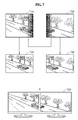
- FIG. 7 illustrates an example of an output image corresponding to an input image to which a first blending mask is applied according to an embodiment.
- the panoramic image outputting apparatus 120 of FIG. 1 may stitch a first input image 710 obtained by applying the blending mask 630 of FIG. 6 and a second input image 720 obtained by applying the blending mask 640 of FIG. 6 to output a first output image 730 and a second output image 740 , respectively.
- the first output image 730 may include a greater right area than the first input image 710 through stitching of a left area of the second input image 720 to a right area of the first input image 710 .
- the second output image 740 may include a greater left area than the second input image 720 through stitching of the left area of the second input image 720 to the right area of the first input image 710 .
- the first beam projector and the second beam projector may display the first output image 730 and the second output image 740 to allow the right area of the first output image 730 and the left area of the second output image 740 to overlap each other.
- the display device 130 may not display output images without overlapping the output images.
- the panoramic image outputting apparatus 120 may output a first output image 750 in which the right area of the first input image 710 is deleted based on the blending mask 630 and the second input image 720 , and a second output image 760 in which the left area of the second input image 720 is deleted based on the blending mask 640 and the first input image 710 .
- the first monitor and the second monitor of the display device 130 may output the first output image 750 and the second output image 760 as illustrated in FIG. 7 .
- FIGS. 8A and 8B illustrate examples of a panoramic image outputting method using an LUT according to an embodiment.
- FIG. 8A illustrates Case 1 in which a single display device outputs a panoramic image generated from a first input image C 1 , a second input image C 2 , and a third input image C 3 to display an output image D 1 .
- the LUT generating apparatus 160 of FIG. 1 may determine a transform function T D 1 C 1 based on a transform function T C 1 to transform an input domain pixel coordinate system of the first input image C 1 to a panorama domain pixel coordinate system of the panoramic image and on a transform function T D 1 to transform an output domain pixel coordinate system of the output image D 1 to the panorama domain pixel coordinate system of the panoramic image.
- the LUT generating apparatus 160 may determine a transform function T D 1 C 2 based on a transform function T C 2 to transform an input domain pixel coordinate system of the second input image C 2 to the panorama domain pixel coordinate system of the panoramic image and on the transform function T D 2 to transform the output domain pixel coordinate system of the output image D 1 to the panorama domain pixel coordinate system of the panoramic image.
- the LUT generating apparatus 160 may determine a transform function T D 1 C 3 based on a transform function T C s to transform an input domain pixel coordinate system of the third input image C 3 to the panorama domain pixel coordinate system of the panoramic image and on the transform function T D 1 to transform the output domain pixel coordinate system of the output image D 1 to the panorama domain pixel coordinate system of the panoramic image.
- the LUT generating apparatus 160 may generate a corresponding LUT based on each of the transform function T D 1 C 1 , the transform function T D 1 C 2 , and the transform function T D 1 C 3 .
- the panoramic image outputting apparatus 120 of FIG. 1 may output the output image D 1 by applying the corresponding LUTs to the first input image C 1 , the second input image C 2 , and the third input image C 3 based on the transform function T D 1 C 1 , the transform function T D 1 C 2 , and the transform function T D 1 C 1 , respectively.
- the first input image C 1 , the second input image C 2 , and the third input image C 3 may be geometrically transformed based on a geometric transformation occurring in a process of stitching the input images to be the panoramic image and in a process of displaying the panoramic image as the output image D 1 .
- the panoramic image obtained by stitching the original input images may be displayed as the output image D 1 in a form without the geometrical transformation.
- FIG. 8B illustrates Case 2 in which a first display device and a second display device output a panoramic image generated from a first input image C 1 , a second input image C 2 , and a third input image C 3 to display an output image D 1 .
- the LUT generating apparatus 160 may determine a transform function T D 1 C 1 based on a transform function T C 2 to transform an input domain pixel coordinate system of the first input image C 1 to a panorama domain pixel coordinate system of the panoramic image and on a transform function T D 1 to transform an output domain pixel coordinate system of the output image D 1 to the panorama domain pixel coordinate system of the panoramic image.
- the LUT generating apparatus 160 may generate an LUT LUT D 1 C 1 based on the transform function T D 1 C 1 .
- the LUT generating apparatus 160 may determine a transform function T D 1 C 2 based on a transform function T C s to transform an input domain pixel coordinate system of the second input image C 2 to the panorama domain pixel coordinate system of the panoramic image.
- the LUT generating apparatus 160 may generate an LUT LUT D 1 C 2 based on the transform function T D 1 C 2 .
- the LUT generating apparatus 160 may determine a transform function T D 2 C 2 based on the transform function T C 2 and on a transform function T C 2 to transform an output domain pixel coordinate system of the output image D 2 to the panorama domain pixel coordinate system of the panoramic image.
- the LUT generating apparatus 160 may generate an LUT LUT D 2 C 2 based on the transform function LUT D 2 C 2 .
- the LUT generating apparatus 160 may determine a transform function LUT D 2 C 3 based on a transform function T C s to transform an output domain pixel coordinate system of the third input image C 3 to the panorama domain pixel coordinate system of the panoramic image and on the transform function T D 2 .
- the LUT generating apparatus 160 may generate an LUT LUT D 2 C s based on the transform function T D 2 C s .
- the panoramic image outputting apparatus 120 may output the output image D 1 by applying the LUT LUT D 1 C 2 and the LUT LUT D 1 C 2 to the first input image C 1 and the second input image C 2 .
- the panoramic image outputting apparatus 120 may geometrically transform a right area of the first input image C 1 and a left area of the second input image C 2 by applying the LUT LUT D 1 C 2 .
- the panoramic image outputting apparatus 120 may then output the output image D 1 by adding the geometrically transformed left area of the second input image C 2 to the geometrically transformed right area of the first input image C 1 .
- the panoramic image outputting apparatus 120 may output the output image D 2 by applying the LUT D 2 C 2 and the LUT D 2 C 3 to the second input image C 2 and the third input image C 3 .
- the panoramic image outputting apparatus 120 may apply the LUT LUT D 2 C 2 to a remaining area of the second input image C 2 from which the left area added to the output image D 1 is excluded.
- the panoramic image outputting apparatus 120 may output the output image D 2 by adding a left area of a third input image C 3 geometrically transformed by applying the LUT LUT D 2 C 3 to a right side of the remaining area.
- FIG. 9 illustrates examples of a panoramic image output according to an embodiment.
- a first input image 910 , a second input image 920 , and a third input image 930 are stitched to generate a panoramic image, and a display device corresponding to a multi-projector environment including a first beam projector 901 , a second beam projector 902 , and a third beam projector 903 outputs an output image of the panoramic image.
- Case 1 of FIG. 9 illustrates an example of an output image 940 output by an existing panoramic image outputting apparatus.
- the existing panoramic image outputting apparatus may not perform stitching calibration on input images and rendering calibration based on an output image.
- the output image 940 output by the existing panoramic image outputting apparatus may include an overlapping area 941 between an image output by the first beam projector 901 and an image output by the second beam projector 902 and an overlapping area 942 between the image output by the second beam projector 902 and an image output by the third beam projector 903 .
- Case 2 of FIG. 9 illustrates an example of an output image 950 output using an LUT by the panoramic image outputting apparatus 120 of FIG. 1 .
- the panoramic image outputting apparatus 120 may display the output image 950 which is a seamless image without a section in which images overlap by performing geometric transformation by applying, to the first input image 910 , the second input image 920 , and the third input image 930 , the LUT that maps an output domain pixel coordinate system of the output image 950 to an input domain pixel coordinate system of the input images and by.
- FIG. 10 is a flowchart illustrating an LUT generating method according to an embodiment.
- the processor 220 of FIG. 2 determines first geometric correction information to transform an input domain pixel coordinate system of an input image to a panorama domain pixel coordinate system of a panoramic image.
- the first geometric correction information is a transform function T C x to transform an input domain pixel coordinate system of an input image C x to the panorama domain pixel coordinate system of the panoramic image.
- the processor 220 inversely transforms the first geometric correction information. For example, the processor 220 may calculate a transform function T C x ⁇ 1 by inversely transforming the transform function T C x .
- the processor 220 determines second geometric correction information to transform an output domain pixel coordinate system of an output image to the panorama domain pixel coordinate system of the panoramic image.
- the second geometric correction information is a transform function T D x to transform an output domain pixel coordinate system of an output image D x to the panorama domain pixel coordinate system of the panoramic image.
- the processor 220 determines third geometric correction information to transform the output domain pixel coordinate system of the output image to the input domain pixel coordinate system of the input image based on the first geometric correction information and the second geometric correction information. For example, the processor 220 may determine a transform function T D x C x , which is the third geometric correction information, by combining the transform function T C x ⁇ 1 obtained by inversely transforming the transform function T C x and the transform function T D x .
- the processor 220 generates an LUT that maps the output domain pixel coordinate system of the output image to the input domain pixel coordinate system of the input image based on the third geometric correction information.
- the processor 220 may generate the LUT by determining an input domain pixel coordinate system x C ,y C of an input image corresponding to an output domain pixel coordinate system x D ,y D of an output image based on at least one of a homographic transform function between the output image and a neighboring output image of the output image, a function to determine a Bezier parameter of an output domain pixel coordinate system of the output image, a homographic transform function between the input image and a neighboring input image of the input image, and a function to correct a zoom or a focal point based on geometric transformation.
- FIG. 11 is a flowchart illustrating a panoramic image outputting method according to an embodiment.
- the processor 320 of FIG. 3 applies a first blending mask to an input image.
- the first blending mask is a blending mask B C x of an input image calculated by the LUT generating apparatus 160 of FIG. 1 .
- the processor 320 applies a color correction parameter to the input image to which the first blending mask is applied.
- the color correction parameter is a color correction parameter of the input image calculated by the LUT generating apparatus 160 .
- the processor 320 transforms the input image to which the first blending mask is applied in operation 1110 to an output image using an LUT generated by the LUT generating apparatus 160 .
- the processor 320 applies a second blending mask to the output image.
- the second blending mask is a blending mask B D x of an output image calculated by the LUT generating apparatus 160 .
- the transmitter 330 of FIG. 3 transmits, to the display device 130 of FIG. 1 , the output image to which the second blending mask is applied by the processor 320 to allow the display device 130 to display the output image.
- generating an LUT that maps an output domain pixel coordinate system of an output image to an input domain pixel coordinate system of an input image may enable simultaneous processing of geometric transformation occurring in a process of generating a panoramic image by stitching input images and geometric transformation occurring in a process of displaying the panoramic image through a display device.
- outputting a panoramic image using an LUT that maps an output domain pixel coordinate system of an output image to an input domain pixel coordinate system of an input image may enable minimization of an image processing operation used to display the panoramic image.
Abstract
Description
(x i g ,y i g)=Hc i(γi)(x i C ,y i C)) [Equation 1]
(x i g ,y i g)=H Dk −1(x k D ,y K D) [Equation 2]
(x i g ,y i g)=H Dk −1βk −1(x k D ,y K D) [Equation 3]
C i,k =T D
(x i,k C ,y i,k C)=γi −1 H Ci −1 H Dk −1βk −1(x k D ,y K D) [Equation 6]
(x k DH ,y k DH)=βk −1(x k D ,y k D) [Equation 7]
| TABLE 1 | ||||
| Source x* | Source y* | Destination x+ | Destination y+ | |
| −10 | −1 | 0 | 0 | |
| 50 | −15 | 50 | 0 | |
| 122 | −2 | 100 | 0 | |
| −15 | 45 | 0 | 50 | |
| 50 | 45 | 50 | 50 | |
| 134 | 45 | 100 | 50 | |
| −8 | 120 | 0 | 100 | |
| 50 | 170 | 50 | 100 | |
| 124 | 115 | 100 | 100 | |
Claims (14)
Applications Claiming Priority (2)
| Application Number | Priority Date | Filing Date | Title |
|---|---|---|---|
| KR1020150047735A KR102328020B1 (en) | 2015-04-03 | 2015-04-03 | System and method for displaying panorama image using single look-up table |
| KR10-2015-0047735 | 2015-04-03 |
Publications (2)
| Publication Number | Publication Date |
|---|---|
| US20160292821A1 US20160292821A1 (en) | 2016-10-06 |
| US9870601B2 true US9870601B2 (en) | 2018-01-16 |
Family
ID=57016223
Family Applications (1)
| Application Number | Title | Priority Date | Filing Date |
|---|---|---|---|
| US15/089,993 Expired - Fee Related US9870601B2 (en) | 2015-04-03 | 2016-04-04 | System and method for displaying panoramic image using single look-up table |
Country Status (2)
| Country | Link |
|---|---|
| US (1) | US9870601B2 (en) |
| KR (1) | KR102328020B1 (en) |
Families Citing this family (22)
| Publication number | Priority date | Publication date | Assignee | Title |
|---|---|---|---|---|
| US10075757B2 (en) * | 2014-09-19 | 2018-09-11 | Foundation Partners Group, Llc | Multi-sensory environment room |
| JP6582557B2 (en) * | 2015-05-28 | 2019-10-02 | 株式会社ソシオネクスト | Drawing apparatus, drawing method, and drawing program |
| US9984436B1 (en) * | 2016-03-04 | 2018-05-29 | Scott Zhihao Chen | Method and system for real-time equirectangular projection |
| KR101704362B1 (en) * | 2016-11-18 | 2017-02-08 | 최재용 | System for real time making of panoramic video base on lookup table and Method for using the same |
| KR101725024B1 (en) * | 2016-11-18 | 2017-04-07 | 최재용 | System for real time making of 360 degree VR video base on lookup table and Method for using the same |
| US10497094B2 (en) * | 2016-12-28 | 2019-12-03 | Nokia Technologies Oy | Method and apparatus for multi-band blending of a seam in an image derived from multiple cameras |
| CN106651808B (en) * | 2016-12-29 | 2020-05-08 | 北京爱奇艺科技有限公司 | Fisheye diagram conversion method and device |
| JP7052225B2 (en) * | 2017-06-06 | 2022-04-12 | 富士通株式会社 | Information processing equipment, information processing system and information processing method |
| GB2565043B (en) * | 2017-06-22 | 2022-02-23 | Avago Tech Int Sales Pte Lid | Apparatus and method for stitching together multiple images |
| CN107392851A (en) * | 2017-07-04 | 2017-11-24 | 上海小蚁科技有限公司 | Method and apparatus for generating panoramic picture |
| CN107318010B (en) * | 2017-07-05 | 2019-10-11 | 上海小蚁科技有限公司 | Method and apparatus for generating stereoscopic panoramic image |
| KR102336997B1 (en) | 2017-08-16 | 2021-12-08 | 삼성전자 주식회사 | Server, display apparatus and control method thereof |
| KR102198217B1 (en) | 2018-04-11 | 2021-01-04 | 한국전자통신연구원 | Look-up table based stitching image generating apparatus and method |
| KR102383669B1 (en) * | 2018-10-23 | 2022-04-06 | 한국전자통신연구원 | Parallax minimized stitching using HLBP descriptor |
| CN110084743B (en) * | 2019-01-25 | 2023-04-14 | 电子科技大学 | Image splicing and positioning method based on multi-flight-zone initial flight path constraint |
| CN110097498B (en) * | 2019-01-25 | 2023-03-31 | 电子科技大学 | Multi-flight-zone image splicing and positioning method based on unmanned aerial vehicle flight path constraint |
| US10715783B1 (en) * | 2019-03-01 | 2020-07-14 | Adobe Inc. | Stereo-aware panorama conversion for immersive media |
| KR102348429B1 (en) * | 2019-12-23 | 2022-01-10 | 서경대학교 산학협력단 | Image distribution and conversion device for multi-projector image alignment and aligning method using the same |
| WO2021132832A1 (en) * | 2019-12-23 | 2021-07-01 | 서경대학교 산학협력단 | Image distribution and conversion device for multi-projector image registration and image registration method using same |
| KR20220025600A (en) | 2020-08-24 | 2022-03-03 | 삼성전자주식회사 | Method and apparatus for generating image |
| CN112435203B (en) * | 2020-12-14 | 2022-11-22 | 中国人民解放军空军航空大学 | Panoramic camera image geometric correction method without control points |
| US20230009944A1 (en) * | 2021-07-09 | 2023-01-12 | Rockwell Collins, Inc. | Configurable low resource subsample image mask for merging in a distorted image space |
Citations (53)
| Publication number | Priority date | Publication date | Assignee | Title |
|---|---|---|---|---|
| US5130794A (en) | 1990-03-29 | 1992-07-14 | Ritchey Kurtis J | Panoramic display system |
| US5881211A (en) * | 1995-12-11 | 1999-03-09 | Dainippon Screen Mfg. Co., Ltd. | Data conversion table changing |
| US6058208A (en) * | 1994-10-26 | 2000-05-02 | Matsushita Electric Industrial Co., Ltd. | Color correction device and color correction method |
| US6075905A (en) * | 1996-07-17 | 2000-06-13 | Sarnoff Corporation | Method and apparatus for mosaic image construction |
| US6078701A (en) * | 1997-08-01 | 2000-06-20 | Sarnoff Corporation | Method and apparatus for performing local to global multiframe alignment to construct mosaic images |
| US6173087B1 (en) * | 1996-11-13 | 2001-01-09 | Sarnoff Corporation | Multi-view image registration with application to mosaicing and lens distortion correction |
| US6359617B1 (en) * | 1998-09-25 | 2002-03-19 | Apple Computer, Inc. | Blending arbitrary overlaying images into panoramas |
| US20020041717A1 (en) * | 2000-08-30 | 2002-04-11 | Ricoh Company, Ltd. | Image processing method and apparatus and computer-readable storage medium using improved distortion correction |
| US6434280B1 (en) * | 1997-11-10 | 2002-08-13 | Gentech Corporation | System and method for generating super-resolution-enhanced mosaic images |
| US6434265B1 (en) * | 1998-09-25 | 2002-08-13 | Apple Computers, Inc. | Aligning rectilinear images in 3D through projective registration and calibration |
| WO2003027766A2 (en) | 2001-09-27 | 2003-04-03 | Eyesee360, Inc. | System and method for panoramic imaging |
| US20030133020A1 (en) * | 2001-12-29 | 2003-07-17 | Lg Electronics Inc. | Apparatus and method for generating mosaic images |
| US20030164826A1 (en) * | 2002-03-04 | 2003-09-04 | Lavelle Michael G. | Reading or writing a non-super sampled image into a super sampled buffer |
| US6788828B2 (en) * | 1996-05-28 | 2004-09-07 | Canon Kabushiki Kaisha | Adaptive image combination according to image sensing condition |
| US20050275911A1 (en) * | 2003-09-18 | 2005-12-15 | Fuji Photo Film Co., Ltd. | Image processing method and device enabling faithful reproduction of appearance and further preferred color reproduction of appearance, image output device and digital camera using the same, and image processing program for executing the image processing method and recording medium on which the program is recorded |
| US7006706B2 (en) * | 2002-04-12 | 2006-02-28 | Hewlett-Packard Development Company, L.P. | Imaging apparatuses, mosaic image compositing methods, video stitching methods and edgemap generation methods |
| US20060050074A1 (en) * | 2004-09-09 | 2006-03-09 | Silicon Optix Inc. | System and method for representing a general two dimensional spatial transformation |
| US7046401B2 (en) | 2001-06-01 | 2006-05-16 | Hewlett-Packard Development Company, L.P. | Camera-based document scanning system using multiple-pass mosaicking |
| US20070019884A1 (en) * | 2002-11-14 | 2007-01-25 | Microsoft Corporation | Modeling reflections within an image sequence |
| US7317558B2 (en) * | 2002-03-28 | 2008-01-08 | Sanyo Electric Co., Ltd. | System and method for image processing of multiple images |
| US7414595B1 (en) * | 2003-12-07 | 2008-08-19 | Advanced Simulation Displays Co. | Virtual mosaic wide field of view display system |
| US20080247667A1 (en) * | 2007-04-05 | 2008-10-09 | Hailin Jin | Laying Out Multiple Images |
| US20090066726A1 (en) * | 2007-09-10 | 2009-03-12 | Toyota Jidosha Kabushiki Kaisha | Composite image-generating device and computer-readable medium storing program for causing computer to function as composite image-generating device |
| WO2009055913A1 (en) | 2007-10-30 | 2009-05-07 | Cedara Software Corp. | System and method for image stitching |
| US7532766B2 (en) * | 2001-07-12 | 2009-05-12 | Do Labs | Method and system for producing formatted data related to geometric distortions |
| US20100033553A1 (en) | 2008-08-08 | 2010-02-11 | Zoran Corporation | In-camera panorama image stitching assistance |
| US20100039562A1 (en) * | 2008-04-09 | 2010-02-18 | University Of Kentucky Research Foundation (Ukrf) | Source and output device-independent pixel compositor device adapted to incorporate the digital visual interface (DVI) |
| US20100054628A1 (en) * | 2008-08-28 | 2010-03-04 | Zoran Corporation | Robust fast panorama stitching in mobile phones or cameras |
| US20100150406A1 (en) * | 2008-12-12 | 2010-06-17 | Jing Xiao | Virtual Masking Using Rigid Parametric Modeling |
| US7840067B2 (en) | 2003-10-24 | 2010-11-23 | Arcsoft, Inc. | Color matching and color correction for images forming a panoramic image |
| US7843465B1 (en) * | 2007-05-31 | 2010-11-30 | Zoran Corporation | Method and apparatus for mapping a multi-dimensional signal from one space to another space |
| US7881559B2 (en) * | 2006-09-04 | 2011-02-01 | Samsung Electronics Co., Ltd. | Method for taking panorama mosaic photograph with a portable terminal |
| US20110200271A1 (en) * | 2010-02-16 | 2011-08-18 | Mohammed Shoaib | Method and apparatus for high-speed and low-complexity piecewise geometric transformation of signals |
| US8041144B2 (en) * | 2006-10-17 | 2011-10-18 | Samsung Electronics Co., Ltd. | Apparatus and method for improving visibility of an image in a high illuminance environment |
| US8045796B2 (en) * | 2006-08-31 | 2011-10-25 | Sony Corporation | Image processing device and image processing method performing color conversion processing using a lookup table |
| US8073259B1 (en) * | 2007-08-22 | 2011-12-06 | Adobe Systems Incorporated | Method and apparatus for image feature matching in automatic image stitching |
| WO2012056437A1 (en) | 2010-10-29 | 2012-05-03 | École Polytechnique Fédérale De Lausanne (Epfl) | Omnidirectional sensor array system |
| US8194993B1 (en) * | 2008-08-29 | 2012-06-05 | Adobe Systems Incorporated | Method and apparatus for matching image metadata to a profile database to determine image processing parameters |
| US20120149432A1 (en) | 2008-05-19 | 2012-06-14 | Peter Lablans | Systems and Methods for Concurrently Playing Multiple Images from a Storage Medium |
| US20120169842A1 (en) * | 2010-12-16 | 2012-07-05 | Chuang Daniel B | Imaging systems and methods for immersive surveillance |
| US8275217B2 (en) * | 2006-08-31 | 2012-09-25 | Fraunhofer-Gesellschaft Zur Foerderung Der Angewandten Forschung E.V. | Apparatus and method for combining several sub-images for any imaging surface areas |
| US8325247B2 (en) | 2007-07-20 | 2012-12-04 | Techwell Japan K.K. | Image processing apparatus and camera system |
| US8351740B2 (en) * | 2007-12-11 | 2013-01-08 | Canon Kabushiki Kaisha | Correlatability analysis for sparse alignment |
| US20130194292A1 (en) * | 2012-01-31 | 2013-08-01 | Electronics And Telecommunications Research Institute | Apparatus and method for correcting color of image projection device |
| US8630031B1 (en) * | 2006-06-27 | 2014-01-14 | Marvell International Ltd. | Color adjustment for a scanned image |
| US20140071228A1 (en) * | 2012-09-12 | 2014-03-13 | National University of Sciences & Technology(NUST) | Color correction apparatus for panorama video stitching and method for selecting reference image using the same |
| US20140240452A1 (en) | 2013-02-27 | 2014-08-28 | Electronics And Telecommunications Research Institute | Apparatus and method for creating panorama |
| US8896662B2 (en) | 2002-01-23 | 2014-11-25 | Scallop Imaging, Llc | Method of creating a virtual window |
| US9098910B2 (en) * | 2008-09-29 | 2015-08-04 | Mobotix Ag | Method for generating video data stream |
| US9210310B2 (en) * | 2013-10-30 | 2015-12-08 | Lite-On Technology Corporation | Image capturing module |
| US9307216B2 (en) * | 2013-05-14 | 2016-04-05 | Funai Electric Co., Ltd. | Video display apparatus using adjustment images |
| US20170093571A1 (en) * | 2015-09-24 | 2017-03-30 | Intel Corporation | Double affine mapped s-box hardware accelerator |
| US9613408B2 (en) * | 2014-09-25 | 2017-04-04 | Intel Corporation | High dynamic range image composition using multiple images |
Family Cites Families (3)
| Publication number | Priority date | Publication date | Assignee | Title |
|---|---|---|---|---|
| JP2001333303A (en) | 2000-05-23 | 2001-11-30 | Sharp Corp | Omnidirectional vision system |
| JP2005005816A (en) | 2003-06-09 | 2005-01-06 | Sharp Corp | Wide angle camera and wide angle camera system |
| US8600194B2 (en) * | 2011-05-17 | 2013-12-03 | Apple Inc. | Positional sensor-assisted image registration for panoramic photography |
-
2015
- 2015-04-03 KR KR1020150047735A patent/KR102328020B1/en active IP Right Grant
-
2016
- 2016-04-04 US US15/089,993 patent/US9870601B2/en not_active Expired - Fee Related
Patent Citations (53)
| Publication number | Priority date | Publication date | Assignee | Title |
|---|---|---|---|---|
| US5130794A (en) | 1990-03-29 | 1992-07-14 | Ritchey Kurtis J | Panoramic display system |
| US6058208A (en) * | 1994-10-26 | 2000-05-02 | Matsushita Electric Industrial Co., Ltd. | Color correction device and color correction method |
| US5881211A (en) * | 1995-12-11 | 1999-03-09 | Dainippon Screen Mfg. Co., Ltd. | Data conversion table changing |
| US6788828B2 (en) * | 1996-05-28 | 2004-09-07 | Canon Kabushiki Kaisha | Adaptive image combination according to image sensing condition |
| US6075905A (en) * | 1996-07-17 | 2000-06-13 | Sarnoff Corporation | Method and apparatus for mosaic image construction |
| US6173087B1 (en) * | 1996-11-13 | 2001-01-09 | Sarnoff Corporation | Multi-view image registration with application to mosaicing and lens distortion correction |
| US6078701A (en) * | 1997-08-01 | 2000-06-20 | Sarnoff Corporation | Method and apparatus for performing local to global multiframe alignment to construct mosaic images |
| US6434280B1 (en) * | 1997-11-10 | 2002-08-13 | Gentech Corporation | System and method for generating super-resolution-enhanced mosaic images |
| US6434265B1 (en) * | 1998-09-25 | 2002-08-13 | Apple Computers, Inc. | Aligning rectilinear images in 3D through projective registration and calibration |
| US6359617B1 (en) * | 1998-09-25 | 2002-03-19 | Apple Computer, Inc. | Blending arbitrary overlaying images into panoramas |
| US20020041717A1 (en) * | 2000-08-30 | 2002-04-11 | Ricoh Company, Ltd. | Image processing method and apparatus and computer-readable storage medium using improved distortion correction |
| US7046401B2 (en) | 2001-06-01 | 2006-05-16 | Hewlett-Packard Development Company, L.P. | Camera-based document scanning system using multiple-pass mosaicking |
| US7532766B2 (en) * | 2001-07-12 | 2009-05-12 | Do Labs | Method and system for producing formatted data related to geometric distortions |
| WO2003027766A2 (en) | 2001-09-27 | 2003-04-03 | Eyesee360, Inc. | System and method for panoramic imaging |
| US20030133020A1 (en) * | 2001-12-29 | 2003-07-17 | Lg Electronics Inc. | Apparatus and method for generating mosaic images |
| US8896662B2 (en) | 2002-01-23 | 2014-11-25 | Scallop Imaging, Llc | Method of creating a virtual window |
| US20030164826A1 (en) * | 2002-03-04 | 2003-09-04 | Lavelle Michael G. | Reading or writing a non-super sampled image into a super sampled buffer |
| US7317558B2 (en) * | 2002-03-28 | 2008-01-08 | Sanyo Electric Co., Ltd. | System and method for image processing of multiple images |
| US7006706B2 (en) * | 2002-04-12 | 2006-02-28 | Hewlett-Packard Development Company, L.P. | Imaging apparatuses, mosaic image compositing methods, video stitching methods and edgemap generation methods |
| US20070019884A1 (en) * | 2002-11-14 | 2007-01-25 | Microsoft Corporation | Modeling reflections within an image sequence |
| US20050275911A1 (en) * | 2003-09-18 | 2005-12-15 | Fuji Photo Film Co., Ltd. | Image processing method and device enabling faithful reproduction of appearance and further preferred color reproduction of appearance, image output device and digital camera using the same, and image processing program for executing the image processing method and recording medium on which the program is recorded |
| US7840067B2 (en) | 2003-10-24 | 2010-11-23 | Arcsoft, Inc. | Color matching and color correction for images forming a panoramic image |
| US7414595B1 (en) * | 2003-12-07 | 2008-08-19 | Advanced Simulation Displays Co. | Virtual mosaic wide field of view display system |
| US20060050074A1 (en) * | 2004-09-09 | 2006-03-09 | Silicon Optix Inc. | System and method for representing a general two dimensional spatial transformation |
| US8630031B1 (en) * | 2006-06-27 | 2014-01-14 | Marvell International Ltd. | Color adjustment for a scanned image |
| US8275217B2 (en) * | 2006-08-31 | 2012-09-25 | Fraunhofer-Gesellschaft Zur Foerderung Der Angewandten Forschung E.V. | Apparatus and method for combining several sub-images for any imaging surface areas |
| US8045796B2 (en) * | 2006-08-31 | 2011-10-25 | Sony Corporation | Image processing device and image processing method performing color conversion processing using a lookup table |
| US7881559B2 (en) * | 2006-09-04 | 2011-02-01 | Samsung Electronics Co., Ltd. | Method for taking panorama mosaic photograph with a portable terminal |
| US8041144B2 (en) * | 2006-10-17 | 2011-10-18 | Samsung Electronics Co., Ltd. | Apparatus and method for improving visibility of an image in a high illuminance environment |
| US20080247667A1 (en) * | 2007-04-05 | 2008-10-09 | Hailin Jin | Laying Out Multiple Images |
| US7843465B1 (en) * | 2007-05-31 | 2010-11-30 | Zoran Corporation | Method and apparatus for mapping a multi-dimensional signal from one space to another space |
| US8325247B2 (en) | 2007-07-20 | 2012-12-04 | Techwell Japan K.K. | Image processing apparatus and camera system |
| US8073259B1 (en) * | 2007-08-22 | 2011-12-06 | Adobe Systems Incorporated | Method and apparatus for image feature matching in automatic image stitching |
| US20090066726A1 (en) * | 2007-09-10 | 2009-03-12 | Toyota Jidosha Kabushiki Kaisha | Composite image-generating device and computer-readable medium storing program for causing computer to function as composite image-generating device |
| WO2009055913A1 (en) | 2007-10-30 | 2009-05-07 | Cedara Software Corp. | System and method for image stitching |
| US8351740B2 (en) * | 2007-12-11 | 2013-01-08 | Canon Kabushiki Kaisha | Correlatability analysis for sparse alignment |
| US20100039562A1 (en) * | 2008-04-09 | 2010-02-18 | University Of Kentucky Research Foundation (Ukrf) | Source and output device-independent pixel compositor device adapted to incorporate the digital visual interface (DVI) |
| US20120149432A1 (en) | 2008-05-19 | 2012-06-14 | Peter Lablans | Systems and Methods for Concurrently Playing Multiple Images from a Storage Medium |
| US20100033553A1 (en) | 2008-08-08 | 2010-02-11 | Zoran Corporation | In-camera panorama image stitching assistance |
| US20100054628A1 (en) * | 2008-08-28 | 2010-03-04 | Zoran Corporation | Robust fast panorama stitching in mobile phones or cameras |
| US8194993B1 (en) * | 2008-08-29 | 2012-06-05 | Adobe Systems Incorporated | Method and apparatus for matching image metadata to a profile database to determine image processing parameters |
| US9098910B2 (en) * | 2008-09-29 | 2015-08-04 | Mobotix Ag | Method for generating video data stream |
| US20100150406A1 (en) * | 2008-12-12 | 2010-06-17 | Jing Xiao | Virtual Masking Using Rigid Parametric Modeling |
| US20110200271A1 (en) * | 2010-02-16 | 2011-08-18 | Mohammed Shoaib | Method and apparatus for high-speed and low-complexity piecewise geometric transformation of signals |
| WO2012056437A1 (en) | 2010-10-29 | 2012-05-03 | École Polytechnique Fédérale De Lausanne (Epfl) | Omnidirectional sensor array system |
| US20120169842A1 (en) * | 2010-12-16 | 2012-07-05 | Chuang Daniel B | Imaging systems and methods for immersive surveillance |
| US20130194292A1 (en) * | 2012-01-31 | 2013-08-01 | Electronics And Telecommunications Research Institute | Apparatus and method for correcting color of image projection device |
| US20140071228A1 (en) * | 2012-09-12 | 2014-03-13 | National University of Sciences & Technology(NUST) | Color correction apparatus for panorama video stitching and method for selecting reference image using the same |
| US20140240452A1 (en) | 2013-02-27 | 2014-08-28 | Electronics And Telecommunications Research Institute | Apparatus and method for creating panorama |
| US9307216B2 (en) * | 2013-05-14 | 2016-04-05 | Funai Electric Co., Ltd. | Video display apparatus using adjustment images |
| US9210310B2 (en) * | 2013-10-30 | 2015-12-08 | Lite-On Technology Corporation | Image capturing module |
| US9613408B2 (en) * | 2014-09-25 | 2017-04-04 | Intel Corporation | High dynamic range image composition using multiple images |
| US20170093571A1 (en) * | 2015-09-24 | 2017-03-30 | Intel Corporation | Double affine mapped s-box hardware accelerator |
Non-Patent Citations (3)
| Title |
|---|
| "Generating Panoramic Views by Stitching Multiple Fisheye Images," Altera Corporation, May 2009, pp. 1-9. |
| J. Javier Yebes et al., "Surrounding View for Enhancing Safety on Vehicles," Proceedings of the 2012 IEEE Intelligent Vehicles Symposium Workshops, 2012, pp. 1-6. |
| Phillipe Colantoni et al., "Analysis of Multispectral Images of Paintings," 14th European Signal Processing Conference (EUSIPCO 2006), Sep. 4-8, 2006, pp. 1-5, Florence, Italy. EURASIP. |
Also Published As
| Publication number | Publication date |
|---|---|
| KR102328020B1 (en) | 2021-11-17 |
| KR20160118868A (en) | 2016-10-12 |
| US20160292821A1 (en) | 2016-10-06 |
Similar Documents
| Publication | Publication Date | Title |
|---|---|---|
| US9870601B2 (en) | System and method for displaying panoramic image using single look-up table | |
| EP3565739B1 (en) | Rear-stitched view panorama for rear-view visualization | |
| JP3925521B2 (en) | Keystone correction using part of the screen edge | |
| US7854518B2 (en) | Mesh for rendering an image frame | |
| JP2022528659A (en) | Projector keystone correction methods, devices, systems and readable storage media | |
| US9533618B2 (en) | Method, apparatus and system for processing a display from a surround view camera solution | |
| US6695451B1 (en) | Multi-projection image display device | |
| US7907792B2 (en) | Blend maps for rendering an image frame | |
| US9900505B2 (en) | Panoramic video from unstructured camera arrays with globally consistent parallax removal | |
| US7800628B2 (en) | System and method for generating scale maps | |
| US9137504B2 (en) | System and method for projecting multiple image streams | |
| US20030067587A1 (en) | Multi-projection image display device | |
| TWI242374B (en) | Image processing system, projector, program, information storing medium, and image processing method | |
| EP3163535A1 (en) | Wide-area image acquisition method and device | |
| JP2019008286A (en) | Projection system and display image correction method | |
| US20070291184A1 (en) | System and method for displaying images | |
| KR20160034847A (en) | System and method for calibrating a display system using a short throw camera | |
| WO2005002240A1 (en) | Method for calculating display characteristic correction data, program for calculating display characteristic correction data, and device for calculating display characteristic correction data | |
| JP2004274354A (en) | System and method for processing image, projector, program and information storage medium | |
| JP2009152798A (en) | Image signal processing apparatus, image signal processing method, image projecting system, image projecting method, and program | |
| JP2011139368A (en) | Control apparatus and control method for capturing device | |
| TWI676855B (en) | Projector calibration method and projection system using the same | |
| US9473709B2 (en) | Image blending system and method for image blending | |
| US20020009699A1 (en) | Data receiving device and image forming apparatus using same | |
| JP2008211355A (en) | Projector, program, and information storage medium |
Legal Events
| Date | Code | Title | Description |
|---|---|---|---|
| AS | Assignment |
Owner name: NATIONAL UNIVERSITY OF SCIENCES & TECHNOLOGY, PAKI Free format text: ASSIGNMENT OF ASSIGNORS INTEREST;ASSIGNORS:CHO, YONG JU;SEOK, JOO MYOUNG;AHN, SANG WOO;AND OTHERS;SIGNING DATES FROM 20160307 TO 20160325;REEL/FRAME:038185/0513 Owner name: ELECTRONICS AND TELECOMMUNICATIONS RESEARCH INSTIT Free format text: ASSIGNMENT OF ASSIGNORS INTEREST;ASSIGNORS:CHO, YONG JU;SEOK, JOO MYOUNG;AHN, SANG WOO;AND OTHERS;SIGNING DATES FROM 20160307 TO 20160325;REEL/FRAME:038185/0513 |
|
| STCF | Information on status: patent grant |
Free format text: PATENTED CASE |
|
| FEPP | Fee payment procedure |
Free format text: PETITION RELATED TO MAINTENANCE FEES GRANTED (ORIGINAL EVENT CODE: PTGR); ENTITY STATUS OF PATENT OWNER: SMALL ENTITY |
|
| CC | Certificate of correction | ||
| FEPP | Fee payment procedure |
Free format text: MAINTENANCE FEE REMINDER MAILED (ORIGINAL EVENT CODE: REM.); ENTITY STATUS OF PATENT OWNER: SMALL ENTITY |
|
| LAPS | Lapse for failure to pay maintenance fees |
Free format text: PATENT EXPIRED FOR FAILURE TO PAY MAINTENANCE FEES (ORIGINAL EVENT CODE: EXP.); ENTITY STATUS OF PATENT OWNER: SMALL ENTITY |
|
| STCH | Information on status: patent discontinuation |
Free format text: PATENT EXPIRED DUE TO NONPAYMENT OF MAINTENANCE FEES UNDER 37 CFR 1.362 |
|
| FP | Lapsed due to failure to pay maintenance fee |
Effective date: 20220116 |