US9870438B2 - Computerized method for producing a production plant model - Google Patents
Computerized method for producing a production plant model Download PDFInfo
- Publication number
- US9870438B2 US9870438B2 US14/653,913 US201314653913A US9870438B2 US 9870438 B2 US9870438 B2 US 9870438B2 US 201314653913 A US201314653913 A US 201314653913A US 9870438 B2 US9870438 B2 US 9870438B2
- Authority
- US
- United States
- Prior art keywords
- module
- container
- model
- assigned
- grid field
- Prior art date
- Legal status (The legal status is an assumption and is not a legal conclusion. Google has not performed a legal analysis and makes no representation as to the accuracy of the status listed.)
- Active, expires
Links
Images


Classifications
-
- G06F17/5004—
-
- G—PHYSICS
- G06—COMPUTING OR CALCULATING; COUNTING
- G06F—ELECTRIC DIGITAL DATA PROCESSING
- G06F30/00—Computer-aided design [CAD]
- G06F30/10—Geometric CAD
- G06F30/13—Architectural design, e.g. computer-aided architectural design [CAAD] related to design of buildings, bridges, landscapes, production plants or roads
-
- B—PERFORMING OPERATIONS; TRANSPORTING
- B01—PHYSICAL OR CHEMICAL PROCESSES OR APPARATUS IN GENERAL
- B01J—CHEMICAL OR PHYSICAL PROCESSES, e.g. CATALYSIS OR COLLOID CHEMISTRY; THEIR RELEVANT APPARATUS
- B01J19/00—Chemical, physical or physico-chemical processes in general; Their relevant apparatus
-
- G—PHYSICS
- G05—CONTROLLING; REGULATING
- G05B—CONTROL OR REGULATING SYSTEMS IN GENERAL; FUNCTIONAL ELEMENTS OF SUCH SYSTEMS; MONITORING OR TESTING ARRANGEMENTS FOR SUCH SYSTEMS OR ELEMENTS
- G05B19/00—Program-control systems
- G05B19/02—Program-control systems electric
- G05B19/418—Total factory control, i.e. centrally controlling a plurality of machines, e.g. direct or distributed numerical control [DNC], flexible manufacturing systems [FMS], integrated manufacturing systems [IMS] or computer integrated manufacturing [CIM]
- G05B19/41885—Total factory control, i.e. centrally controlling a plurality of machines, e.g. direct or distributed numerical control [DNC], flexible manufacturing systems [FMS], integrated manufacturing systems [IMS] or computer integrated manufacturing [CIM] characterised by modeling, simulation of the manufacturing system
-
- B—PERFORMING OPERATIONS; TRANSPORTING
- B01—PHYSICAL OR CHEMICAL PROCESSES OR APPARATUS IN GENERAL
- B01J—CHEMICAL OR PHYSICAL PROCESSES, e.g. CATALYSIS OR COLLOID CHEMISTRY; THEIR RELEVANT APPARATUS
- B01J2219/00—Chemical, physical or physico-chemical processes in general; Their relevant apparatus
- B01J2219/00002—Chemical plants
- B01J2219/00018—Construction aspects
- B01J2219/0002—Plants assembled from modules joined together
-
- B—PERFORMING OPERATIONS; TRANSPORTING
- B01—PHYSICAL OR CHEMICAL PROCESSES OR APPARATUS IN GENERAL
- B01J—CHEMICAL OR PHYSICAL PROCESSES, e.g. CATALYSIS OR COLLOID CHEMISTRY; THEIR RELEVANT APPARATUS
- B01J2219/00—Chemical, physical or physico-chemical processes in general; Their relevant apparatus
- B01J2219/00049—Controlling or regulating processes
- B01J2219/00243—Mathematical modelling
-
- G—PHYSICS
- G05—CONTROLLING; REGULATING
- G05B—CONTROL OR REGULATING SYSTEMS IN GENERAL; FUNCTIONAL ELEMENTS OF SUCH SYSTEMS; MONITORING OR TESTING ARRANGEMENTS FOR SUCH SYSTEMS OR ELEMENTS
- G05B2219/00—Program-control systems
- G05B2219/30—Nc systems
- G05B2219/32—Operator till task planning
- G05B2219/32085—Layout of factory, facility, cell, production system planning
-
- Y—GENERAL TAGGING OF NEW TECHNOLOGICAL DEVELOPMENTS; GENERAL TAGGING OF CROSS-SECTIONAL TECHNOLOGIES SPANNING OVER SEVERAL SECTIONS OF THE IPC; TECHNICAL SUBJECTS COVERED BY FORMER USPC CROSS-REFERENCE ART COLLECTIONS [XRACs] AND DIGESTS
- Y02—TECHNOLOGIES OR APPLICATIONS FOR MITIGATION OR ADAPTATION AGAINST CLIMATE CHANGE
- Y02P—CLIMATE CHANGE MITIGATION TECHNOLOGIES IN THE PRODUCTION OR PROCESSING OF GOODS
- Y02P90/00—Enabling technologies with a potential contribution to greenhouse gas [GHG] emissions mitigation
- Y02P90/02—Total factory control, e.g. smart factories, flexible manufacturing systems [FMS] or integrated manufacturing systems [IMS]
-
- Y02P90/24—
-
- Y02P90/26—
Definitions
- the present invention relates to a computerized method for producing a two-dimensional plant model of a modular production plant for producing a chemical product.
- the object of the invention is to provide a novel plant concept which can be used to considerably reduce the amount of effort associated with the production of different chemical products in comparison with the conventional procedure.
- Patent claim 1 proposes a computerized method for producing a two-dimensional plant model of a modular production plant for producing a chemical product, wherein the production plant has at least two process modules, which can be connected to one another for production purposes, and at least one process container in which the process modules can be at least partially accommodated as intended,
- the production plant may also have two or more process containers which can be connected to one another for production purposes.
- the process containers are preferably units which can be transported as a whole, can be transported to a desired production site at which an accordingly equipped production plant is intended to be erected, and can be transported away from this site after the desired production has been concluded. This makes it possible to easily reuse individual process containers at different production sites in a manner that reduces production costs.
- a process container may have a housing which enables simple transport of the process container and in which process modules suitable for carrying out an entire process or a particular process section are arranged and connected to one another for production purposes.
- a process container may have, for example, functionalities for heating, cooling, mixing, separating, controlling the pressure, ventilating and/or venting which make it possible to carry out a chemical reaction and control reaction conditions.
- a process container may also be set up to independently carry out an entire process or a particular process section of production. In this case, independently means that the process section is carried out using the process container without the process section or a part of the latter having to be controlled and/or regulated by a device remote from the process container.
- At a production site at least one process container can be connected, preferably via standardized couplings, to a permanently installed communication network and/or to a supply network which can be used to supply the process container with material and/or energy and/or into which materials can be delivered, with the result that at least one chemical batch reaction and/or continuous production can be carried out in a substantially autonomous manner using the process container.
- the supply network may have a compressed air line for supplying compressed air, a feed water line for supplying water, an electrical line for supplying electrical energy, a materials line for supplying starting materials and/or auxiliary materials and/or for discharging products, byproducts and/or waste materials, a cooling line for supplying cold or for dissipating heat and/or a heating line for supplying heat or for removing cold.
- Various wired or wireless communication networks come into consideration as the communication network. Standardized information interchange between the process containers connected to the communication network and/or with superordinate or subordinate devices can be carried out via the communication network.
- the process modules which can be connected to one another for production purposes can be at least partially arranged in a process container as intended.
- the entire arrangement of individual process modules for each process container is minimized in terms of its spatial space requirement and the material needed to arrange it as intended, with the result that, in particular, a maximum number of process modules can be arranged in a process container, thus increasing the variability with which a process container is fitted with process modules.
- the same consequently applies to the variability of the processes or process sections which can be carried out using a process container.
- the container model and the module models are divided into grid fields of the same size.
- the grid fields are preferably square.
- the grid fields may be circular.
- a rectangular or elliptical configuration of the grid fields is possible, but the ability to arrange the process modules relative to the process container is restricted as a result in comparison with a square or circular configuration of the grid fields.
- other polygonal or oval grid fields which are congruent with respect to one another can also be used.
- the module properties and the occupancy properties are boundary conditions with respect to the arrangement of the individual process modules relative to one another and relative to the process container. In the production plant, parts of the process modules are therefore optimally assigned to those sections of the base area of the container and its environment of a predefinable size which correspond to the grid fields of the container model.
- a functional device can be a material and/or energy store which can be connected to a local supply network.
- the occupancy properties of the container model are preferably selected from a group comprising at least the properties “cannot be occupied”, “can be occupied only by an operations room”, “can be occupied only by a functional device”, “preferably not occupied”, “preferably occupied by an operations room” and “preferably occupied by a functional device”.
- each grid field of the container model is assigned one of the properties “inside the container” or “outside the container”. This constitutes a further criterion when arranging the process modules relative to the process container. If a grid field of the container model has the property “inside the container”, this grid field is completely inside the base area of the actual process container. In contrast, if a grid field of the container module has the property “outside the container”, this grid field is completely outside the base area of the actual process container but completely inside the base area of the actual environment of a limited, predefinable size.
- Grid fields of a process module which are assigned a functional device of the respective process module are preferably arranged in grid fields of the container model which have the property “inside the container”.
- each grid field of the container model is assigned an absolute integer coordinate pair (x abs , y abs ), wherein the origin of the underlying absolute coordinate system is arranged inside the base area of the process container.
- Each grid field of a module model is advantageously assigned an integer relative coordinate pair (x rel , y rel ), wherein the origin of the underlying relative coordinate system is arranged inside the base area of the process module. This also makes it possible to easily individualize the grid fields of a module model, which simplifies the assignment of properties to the individual grid fields of the respective module model.
- each module model is assigned a position in the absolute coordinate system, which position is defined by the position of the origin of the respective relative coordinate system inside the absolute coordinate system.
- the ability to arrange a module model relative to the container model constitutes a first degree of freedom of the arrangement of the process modules relative to the process container, which arrangement is to be optimized.
- Each module model is preferably assigned an orientation relative to the absolute coordinate system. If the container model and the module models are subdivided into square grid fields, for example, a module model can be oriented at the relative angles 0°, 90°, 180° or 270° relative to the absolute coordinate system. This relative orientability between module models and container model constitutes a second degree of freedom of the arrangement of the process modules relative to the process container, which arrangement is to be optimized.
- connection variants between grid fields of different module models which are each assigned a functional device, are determined, wherein each connection variant is weighted with a value from a predefinable range of values, in particular from the range of values ⁇ 100, . . . , 100 ⁇ .
- the connection variants are determined, for example, taking into account material and technical connections or relationships between the individual process modules to be arranged relative to a process container. Material relationships may result from given material streams and waste streams. Technical relationships may be due to distance requirements between devices of process modules, which devices are not compatible with one another.
- Connection variants weighted with a negative value preferably result in the distance between grid fields associated with these connection variants being maximized, and connection variants weighted with a positive value result in the distance between grid fields associated with these connection variants being minimized.
- the distance may be maximized, for example, between technical devices which are not compatible with one another. Minimization of the distance may be used, for example, to reduce the length of pipelines between technical devices of process modules.
- connection variant which is weighted with the smallest positive value is selected.
- the module models are also arranged in the container model taking into account at least one of the further conditions selected from the following group:
- the module models are preferably arranged in the container model taking into account all of these further conditions.
- the module models are also arranged in the container model taking into account at least one of the further conditions selected from the following group:
- the module models are preferably also arranged in the container model taking into account all of these further conditions.
- the module models are also arranged in the container model taking into account at least one of the further conditions selected from the following group:
- module models are arranged in the container model assigned to the process container taking into account the arrangement of module models in a further container model assigned to a further process container, wherein the further process container is arranged above, below or beside the process container.
- This refinement substantiates further boundary conditions for arranging process modules relative to a process container.
- the entire arrangement of process modules in a production plant comprising at least two process containers can be accordingly optimized.
- Another advantageous refinement provides for a square standardized transport container, in particular according to DIN ISO 668, to be used as the process container. This makes it possible to easily transport process containers fitted with process modules to the respective production sites using conventional standardized transport means.
- the container model, the module models and the respective relative positions between the module models and the container model are displayed by a display device. This enables a simple control possibility for persons dealing with the planning of a corresponding production plant.
- a method for optimizing an arrangement of at least two process modules of a modular production plant in a process container wherein the module properties, occupancy properties and conditions mentioned above can be used in different combinations with one another for this optimization.
- One aim of this optimization is to provide an arrangement of process modules which is as space-saving as possible, in which case optimization functions are preferably formulated and used for this purpose. If an accordingly optimized arrangement of process modules does not comply with a predefinable maximum number of the conditions mentioned above, the optimized arrangement is provided with a corresponding quality value in order to be able to compare different arrangements with one another after corresponding optimizations, for example.
- FIG. 1 shows an illustration of an exemplary embodiment for the occupancy of the grid fields of a container model by occupancy properties
- FIG. 2 shows an illustration of the assignment of the container model shown in FIG. 1 using absolute coordinate pairs
- FIG. 3 shows an illustration of an exemplary embodiment for the occupancy of the grid fields of a module model by module properties
- FIG. 4 shows an illustration of the container model with three module models arranged therein, and
- FIG. 5 shows an illustration of the container model shown in FIG. 4 after optimization of the arrangement of the three module models relative to one another and relative to the container model.
- FIG. 1 shows an illustration of an exemplary embodiment for the occupancy of the grid fields 1 of a two-dimensional container model 2 by occupancy properties.
- the container model 2 was generated for the base area 3 (illustrated in a framed manner) of a process container (not illustrated in any more detail) and the base area 4 of a container environment which partially surrounds the process container and has a predefinable size.
- the container model 2 has been divided into square grid fields 1 of the same size.
- the base area 3 of the process container comprises 4 ⁇ 10 grid fields 1 .
- the occupancy properties are selected from a group comprising the properties “cannot be occupied” (black), “can be occupied only by an operations room” (gray), “can be occupied only by a functional device” (white), “preferably not occupied” (black with hatching), “preferably occupied by an operations room” (gray with hatching) and “preferably occupied by a functional device” (white with hatching).
- functional devices of process modules are preferably arranged inside the process container, whereas operations rooms assigned to process modules may also be arranged outside the process container.
- FIG. 2 shows an illustration of the assignment of the container model 2 shown in FIG. 1 using absolute coordinate pairs (x abs , y abs ).
- the origin of the underlying absolute coordinate system is arranged inside the base area 3 of the process container and is marked using the absolute coordinate pair (0, 0).
- Each grid field 1 of the container model 2 is also assigned one of the properties “inside the container” (with hatching) or “outside the container” (white).
- FIG. 3 shows an illustration of an exemplary embodiment for the occupancy of the grid fields 4 of a module model 5 , produced for the base area of a process module (not illustrated in any more detail), by module properties.
- the module model 5 divided into square grid fields 4 of the same size, wherein the dimensioning of the grid fields 4 of the module model 5 corresponds to that of the grid fields 1 of the container model 2 shown in FIGS. 1 and 2 .
- Each grid field 4 of the module model 5 is assigned a relative coordinate pair (x rel , y rel ), wherein the origin of the underlying relative coordinate system is arranged inside the base area of the process module and is marked with the relative coordinate pair (0, 0).
- Each grid field 4 of the module model 5 is assigned a module property concerning the occupancy of the respective grid field 4 by a functional device of the respective process module, which functional device is arranged above that section of the base area of the respective process module which corresponds to this grid field 4 , or by an operations room which is allocated to the process module and is arranged above that section of the base area of the respective process module which corresponds to this grid field 4 .
- the module properties concerning the occupancy of the respective grid field 4 by a functional device of the respective process module, which functional device is arranged above that section of the base area of the respective process module which corresponds to this grid field 4 are selected from a group which the functional properties “material input” (relative coordinate pair (1, 2)) and “process assembly” (relative coordinate pairs (0, 2), (0, 1), (1, 1), (0, 0) and (1, 0)).
- the module property “process equipment” can be additionally assigned to the grid field 4 having the relative coordinate pair (1, 2).
- the grid fields 4 having the relative coordinate pairs ( ⁇ 1, 2), ( ⁇ 1, 1), ( ⁇ 1, 0), (0, ⁇ 1) and (1, ⁇ 1) are accordingly occupied by the module property “operations room”.
- the grid fields 4 having the relative coordinate pairs (2, 1), (2, 0) and (2, ⁇ 1) are occupied by the module property “material output”.
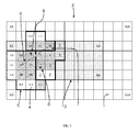
- FIG. 4 shows an illustration of the container model 2 with three module models 5 arranged therein.
- Each module model 5 is assigned a position in the absolute coordinate system, which position is defined by the position of the origin of the respective relative coordinate system inside the absolute coordinate system.
- the process module 5 illustrated on the left has, for example, that position in the absolute coordinate system which is marked by the absolute coordinate pair (1, 0).
- each module model 5 is assigned an orientation relative to the absolute coordinate system. Since the container model 2 and the module models 5 are subdivided into square grid fields 1 and 4 , respectively, a module model 5 can be oriented at the relative angles 0°, 90°, 180° or 270° relative to the absolute coordinate system.
- the process module 5 illustrated on the left is oriented at the relative angle 0° relative to the absolute coordinate system.
- the middle process module 5 is arranged at the position having the absolute coordinate pair (7, 0) and is oriented at the relative angle 270° relative to the absolute coordinate system.
- the process module 5 illustrated on the right is arranged at the position having the absolute coordinate pair (9, 4) and is oriented at the relative angle 0° relative to the absolute coordinate system.
- connection variants between grid fields 4 of different module models 5 which are each assigned a functional device, are determined, wherein each connection variant is weighted with a value from a predefinable range of values, in particular from the range of values ⁇ 100, . . . , 100 ⁇ .
- a predefinable range of values in particular from the range of values ⁇ 100, . . . , 100 ⁇ .
- those grid fields 4 of the module model 5 illustrated on the left which are occupied by the property “material output” can be connected to that grid field 4 of the module model 5 illustrated in the middle which is occupied by the property “material input”.
- These material connections between the module model 5 illustrated on the left and the module model 5 illustrated in the middle are marked with numeral 1 in FIG. 4 .
- These connection variants are indicated by arrows 6 in FIG. 4 .
- connection variant according to which the grid field 4 having the relative coordinate pairs (2, 0) of the module model 5 illustrated on the left is connected to the grid field 4 having the relative coordinate pairs (0, 1) of the module model 5 illustrated in the middle, is weighted with the value 50.
- the two other connection variants indicated by an arrow 6 are each weighted with the value 100.
- connection variants between grid fields 4 of the module model 5 illustrated in the middle which are occupied by the property “material output” and that grid field of the module model 5 illustrated on the right which is occupied by the module property “material input” are marked with numeral 2 in FIG. 4 and are indicated by arrows 7 .
- the connection variant, according to which the grid field 4 having the relative coordinate pairs (2, ⁇ 1) of the module model 5 illustrated in the middle is connected to the grid field 4 having the relative coordinate pairs (0, 0) of the module model 5 illustrated on the right, is weighted with the value 100.
- the other connection variant indicated by an arrow 7 is weighted with the value 50.
- a connection variant between the grid fields 4 of the module model 5 illustrated on the left which are occupied by the property “material output” and that grid field of the module model 5 illustrated on the right which is occupied by the module property “material input” is marked with numeral 3 in FIG. 4 and is indicated by the arrow 8 .
- This connection variant according to which the grid field 4 having the relative coordinate pairs (1, 2) of the module model 5 illustrated on the left is connected to the grid field 4 having the relative coordinate pairs (0, 0) of the module model 5 illustrated on the right, is weighted with the value 50.
- a connection variant between the grid fields 4 of the module model 5 illustrated on the left which are occupied by the property “process equipment” and that grid field of the module model 5 illustrated on the right which is occupied by the module property “material input” is marked with numeral 4 in FIG. 4 and is indicated by the arrow 9 .
- This connection variant according to which the grid field 4 having the relative coordinate pairs (0, 1) of the module model 5 illustrated on the left is connected to the grid field 4 having the relative coordinate pairs (0, 0) of the module model 5 illustrated on the right, is weighted with the value ⁇ 100.
- This connection variant therefore relates to a repelling relationship between the module model illustrated on the left and the module model illustrated on the right.
- connection variants are likewise determined and weighted accordingly. For reasons of clarity, however, further connection variants are not illustrated in FIG. 4 .
- connection variants marked with numerals 1 and 2 for example, that connection variant which is weighted with the smallest positive value is preferably selected.
- FIG. 5 shows an illustration of the container model 2 shown in FIG. 4 after optimization of the arrangement of the three module models 5 relative to one another and relative to the container model 2 .
- those grid fields 4 of the module models 5 which are assigned a functional device of the respective process module are all situated inside the base area 3 of the process container (not illustrated in any more detail).
- Each module model 5 is assigned an optimized position in the absolute coordinate system, which position is defined by the position of the origin of the respective relative coordinate system inside the absolute coordinate system.
- the optimized position of the process module 5 illustrated on the left corresponds to the starting position of this module model 5 , as shown in FIG. 4 , before the optimization is carried out.
- the middle process module 5 is arranged at the optimized position having the absolute coordinate pair (4, 1) and is oriented at the relative angle 270° relative to the absolute coordinate system.
- the process module 5 illustrated on the right is arranged at the optimized position having the absolute coordinate pair (4, 3) and is oriented at the relative angle 180° relative to the absolute coordinate system.
- This optimized arrangement of the module models 5 in the container model 2 is displayed by a display device (not illustrated in any more detail).
Landscapes
- Engineering & Computer Science (AREA)
- Physics & Mathematics (AREA)
- Chemical & Material Sciences (AREA)
- Manufacturing & Machinery (AREA)
- General Physics & Mathematics (AREA)
- General Engineering & Computer Science (AREA)
- Automation & Control Theory (AREA)
- Organic Chemistry (AREA)
- Chemical Kinetics & Catalysis (AREA)
- Quality & Reliability (AREA)
- Geometry (AREA)
- Theoretical Computer Science (AREA)
- Computer Hardware Design (AREA)
- Architecture (AREA)
- Structural Engineering (AREA)
- Computational Mathematics (AREA)
- Mathematical Analysis (AREA)
- Mathematical Optimization (AREA)
- Pure & Applied Mathematics (AREA)
- Evolutionary Computation (AREA)
- Civil Engineering (AREA)
- Management, Administration, Business Operations System, And Electronic Commerce (AREA)
- General Factory Administration (AREA)
Abstract
Description
-
- wherein, for each process container, a common two-dimensional container model of its base area and of the base area of a container environment at least partially surrounding the process container and of a predefinable size is generated,
- wherein, for each process module, a two-dimensional module model of its base area is generated,
- wherein the container model and the module models are divided into grid fields which are of the same size and are preferably square,
- wherein each grid field of a module model is assigned a module property concerning the occupancy of the respective grid field by a functional device of the respective process module, which functional device is arranged above that section of the base area of the respective process module which corresponds to this grid field, by an operations room which is allocated to the process module and is arranged above that section of the base area of the respective process module which corresponds to this grid field, or by a material output of the process module, which output is arranged above that section of the base area of the respective process module which corresponds to this grid field,
- wherein each grid field of the container model is assigned an occupancy property concerning the possibility or impossibility of the respective grid field being occupied by a module property,
- wherein the module models are arranged in the container model taking into account the module properties and the occupancy properties.
-
- a grid field of a module model assigned a functional device of the respective process module must not occupy a grid field of the container model which has already been occupied by a grid field of a further module model assigned a functional device of the respective further process module;
- a grid field of a module model assigned an operations room allocated to the respective process module must not occupy a grid field of the container model which has already been occupied by a grid field of a further module model assigned a functional device of the respective further process module;
- a grid field of a module model assigned a functional device of the respective process module must not occupy a grid field of the container model assigned the occupancy property “cannot be occupied” or “can be occupied only by an operations room”;
- a grid field of a module model assigned an operations room allocated to the respective process module must not occupy a grid field of the container model assigned the occupancy property “cannot be occupied” or “can be occupied only by a functional device”.
-
- a grid field of a module model assigned an operations room allocated to the respective process module should be arranged in a grid field of the container model which has already been occupied by a grid field of a further module model assigned an operations room allocated to the respective further process module;
- a grid field of a module model assigned a functional device of the respective process module should be arranged in a grid field of the container model assigned the occupancy property “can be occupied only by a functional device” or “preferably occupied by a functional device”;
- a grid field of a module model assigned an operations room allocated to the respective process module should be arranged in a grid field of the container model assigned the occupancy property “can be occupied only by an operations room” or “preferably occupied by an operations room”;
- a grid field of a module model assigned a functional device of the respective process module should be arranged in a grid field of the container model which has already been occupied by a grid field of a further module model assigned a material output of the respective further process module;
- a grid field of a module model assigned a material output of the respective process module should be arranged in a grid field of the container model which has already been occupied by a grid field of a further module model assigned a functional device of the respective further process module.
-
- the process modules should be able to be introduced into the process container via a longitudinal side of the latter;
- operations rooms and maintenance rooms for the process modules should be accessible after the process modules have been arranged as intended;
- the process modules should be able to be individually removed from the process container and installed in the latter without other process modules having to be removed for this purpose;
- process streams between process modules arranged as intended should not intersect third process modules.
Claims (18)
Applications Claiming Priority (4)
| Application Number | Priority Date | Filing Date | Title |
|---|---|---|---|
| DE102012112775.1A DE102012112775A1 (en) | 2012-12-20 | 2012-12-20 | Computer-implemented method for manufacturing a production plant model |
| DE102012112775 | 2012-12-20 | ||
| DE102012112775.1 | 2012-12-20 | ||
| PCT/EP2013/077050 WO2014095972A1 (en) | 2012-12-20 | 2013-12-18 | Computerized method for producing a production plant model |
Publications (2)
| Publication Number | Publication Date |
|---|---|
| US20150347636A1 US20150347636A1 (en) | 2015-12-03 |
| US9870438B2 true US9870438B2 (en) | 2018-01-16 |
Family
ID=49943332
Family Applications (1)
| Application Number | Title | Priority Date | Filing Date |
|---|---|---|---|
| US14/653,913 Active 2035-01-18 US9870438B2 (en) | 2012-12-20 | 2013-12-18 | Computerized method for producing a production plant model |
Country Status (8)
| Country | Link |
|---|---|
| US (1) | US9870438B2 (en) |
| EP (1) | EP2936261B1 (en) |
| CN (1) | CN105009009B (en) |
| DE (1) | DE102012112775A1 (en) |
| DK (1) | DK2936261T3 (en) |
| ES (1) | ES2857049T3 (en) |
| PL (1) | PL2936261T3 (en) |
| WO (1) | WO2014095972A1 (en) |
Families Citing this family (1)
| Publication number | Priority date | Publication date | Assignee | Title |
|---|---|---|---|---|
| CN120577477B (en) * | 2025-06-04 | 2025-11-04 | 北京雪迪龙科技股份有限公司 | Gas monitoring and analyzing system with multiple intelligent sensors working cooperatively |
Citations (9)
| Publication number | Priority date | Publication date | Assignee | Title |
|---|---|---|---|---|
| US6470301B1 (en) | 1999-10-08 | 2002-10-22 | Dassault Systemes | Optimization tool for assembly workcell layout |
| US20030069668A1 (en) * | 2001-10-09 | 2003-04-10 | Zurn William Harrison | Modular, robotic road repair machine |
| US7386154B2 (en) * | 2002-03-29 | 2008-06-10 | Universita Degli Studi Di Trieste | Method to identify the mechanical properties of a material |
| US20100047557A1 (en) * | 2007-01-15 | 2010-02-25 | Fraunhofer-Gesellschaft Zur Foerderung Der Angewandten Forschung E.V. | Ceramic and/or powder-metallurgical composite shaped body and method for the production thereof |
| DE212009000008U1 (en) | 2008-09-10 | 2010-09-02 | Evonik Degussa Gmbh | Universal infrastructure for chemical processes |
| US20110227926A1 (en) * | 2010-03-19 | 2011-09-22 | Yokogawa Electric Corporation | Method and apparatus for generating a material flow diagram for an industrial plant |
| US20120019612A1 (en) * | 2008-06-12 | 2012-01-26 | Spandan Choudury | non virtual 3d video/photo generator rendering relative physical proportions of image in display medium (and hence also of the display medium itself) the same as the relative proportions at the original real life location |
| US20150227820A1 (en) * | 2014-02-13 | 2015-08-13 | Oce-Technologies B.V. | System for displaying printer information |
| US9441936B2 (en) * | 2014-07-29 | 2016-09-13 | Plethora Corporation | System and method for automated object measurement |
Family Cites Families (3)
| Publication number | Priority date | Publication date | Assignee | Title |
|---|---|---|---|---|
| JP4381743B2 (en) * | 2003-07-16 | 2009-12-09 | 独立行政法人理化学研究所 | Method and program for generating volume data from boundary representation data |
| KR100753537B1 (en) * | 2006-06-09 | 2007-08-30 | 주식회사 아이너스기술 | Reverse engineering method using mesh data as features |
| DE202009000008U1 (en) * | 2009-01-08 | 2009-03-12 | Bachl, Armin | Holding device for bound reading material |
-
2012
- 2012-12-20 DE DE102012112775.1A patent/DE102012112775A1/en not_active Withdrawn
-
2013
- 2013-12-18 DK DK13818719.0T patent/DK2936261T3/en active
- 2013-12-18 WO PCT/EP2013/077050 patent/WO2014095972A1/en not_active Ceased
- 2013-12-18 EP EP13818719.0A patent/EP2936261B1/en active Active
- 2013-12-18 ES ES13818719T patent/ES2857049T3/en active Active
- 2013-12-18 PL PL13818719T patent/PL2936261T3/en unknown
- 2013-12-18 US US14/653,913 patent/US9870438B2/en active Active
- 2013-12-18 CN CN201380067171.XA patent/CN105009009B/en active Active
Patent Citations (10)
| Publication number | Priority date | Publication date | Assignee | Title |
|---|---|---|---|---|
| US6470301B1 (en) | 1999-10-08 | 2002-10-22 | Dassault Systemes | Optimization tool for assembly workcell layout |
| US20030069668A1 (en) * | 2001-10-09 | 2003-04-10 | Zurn William Harrison | Modular, robotic road repair machine |
| US7386154B2 (en) * | 2002-03-29 | 2008-06-10 | Universita Degli Studi Di Trieste | Method to identify the mechanical properties of a material |
| US20100047557A1 (en) * | 2007-01-15 | 2010-02-25 | Fraunhofer-Gesellschaft Zur Foerderung Der Angewandten Forschung E.V. | Ceramic and/or powder-metallurgical composite shaped body and method for the production thereof |
| US20120019612A1 (en) * | 2008-06-12 | 2012-01-26 | Spandan Choudury | non virtual 3d video/photo generator rendering relative physical proportions of image in display medium (and hence also of the display medium itself) the same as the relative proportions at the original real life location |
| DE212009000008U1 (en) | 2008-09-10 | 2010-09-02 | Evonik Degussa Gmbh | Universal infrastructure for chemical processes |
| US20110163462A1 (en) | 2008-09-10 | 2011-07-07 | Evonik Degussa Gmbh | Universal Infrastructure for Chemical Processes |
| US20110227926A1 (en) * | 2010-03-19 | 2011-09-22 | Yokogawa Electric Corporation | Method and apparatus for generating a material flow diagram for an industrial plant |
| US20150227820A1 (en) * | 2014-02-13 | 2015-08-13 | Oce-Technologies B.V. | System for displaying printer information |
| US9441936B2 (en) * | 2014-07-29 | 2016-09-13 | Plethora Corporation | System and method for automated object measurement |
Non-Patent Citations (5)
| Title |
|---|
| Erdwiens et al.; "Fundamentals for computer-aided layout planning"; Chem. Ing. Tech. 67 (1995) No. 7, p. 853-861-English translation provided. |
| Erdwiens et al.; "Fundamentals for computer-aided layout planning"; Chem. Ing. Tech. 67 (1995) No. 7, p. 853-861—English translation provided. |
| International Search Report from corresponding application PCT/EP2013/077050 dated Apr. 16, 2014. |
| Ritthoff et al.; "Feature-based learning of placement rules as part of the layout planning for chemical plants"; University of Dortmund, Series Computational Intelligence Collaborative Research Center 531; Technical Report, Sep. 2004-English translation provided. |
| Ritthoff et al.; "Feature-based learning of placement rules as part of the layout planning for chemical plants"; University of Dortmund, Series Computational Intelligence Collaborative Research Center 531; Technical Report, Sep. 2004—English translation provided. |
Also Published As
| Publication number | Publication date |
|---|---|
| PL2936261T3 (en) | 2021-06-28 |
| DK2936261T3 (en) | 2021-04-12 |
| WO2014095972A1 (en) | 2014-06-26 |
| EP2936261B1 (en) | 2021-01-20 |
| DE102012112775A1 (en) | 2014-07-10 |
| CN105009009B (en) | 2019-03-22 |
| EP2936261A1 (en) | 2015-10-28 |
| CN105009009A (en) | 2015-10-28 |
| US20150347636A1 (en) | 2015-12-03 |
| ES2857049T3 (en) | 2021-09-28 |
Similar Documents
| Publication | Publication Date | Title |
|---|---|---|
| US10108184B2 (en) | Production installation for a chemical or pharmaceutical product | |
| CN103547122B (en) | data center cooling system and method | |
| US20200256582A1 (en) | Poe controlled light fixtures with incorporated poe controlled variable conditioned air vents | |
| AU2009291162B2 (en) | Universal infrastructure for chemical processes | |
| US20150354201A1 (en) | Method and system for using an industrial site | |
| KR20180062076A (en) | Independent module-type personalization plant cultivating device and plant factory system based on independent module-type personalization plant cultivating device | |
| US20200347627A1 (en) | Self-contained treatment unit for haemodialysis treatments | |
| US9870438B2 (en) | Computerized method for producing a production plant model | |
| US20200163247A1 (en) | Modular and Flexible Data Center and Method of Operation | |
| CN103807986A (en) | Variable-air-volume ventilating system | |
| US20100304656A1 (en) | Integrated aerator for storage and drying silos | |
| RU2598355C2 (en) | Modular data processing centre | |
| CN110469162A (en) | Clean room overall structure and workshop operation method for medicine production | |
| CN102820243B (en) | Semiconductor wafer production device | |
| US20130074974A1 (en) | Ductwork stiffener | |
| CN101240917A (en) | Device for cooling and warming a space in a building | |
| CN111617725B (en) | Processing unit and use of multiple processing units | |
| KR20140005036A (en) | Module type plant factory | |
| CN203984871U (en) | A kind of container data center | |
| KR101256335B1 (en) | A centralized remote control plant growing block and a farm migrant style plant growing system using this block | |
| RU121904U1 (en) | BOILER EQUIPMENT SYSTEM, AND ALSO COMPONENT AND CONSTRUCTION ELEMENTS OF SUCH SYSTEM | |
| CN209749287U (en) | Integrated container plant factory based on air duct air supply | |
| CN102200773A (en) | Method and system for controlling wireless network of bituminous mixing plant | |
| US20080214099A1 (en) | Air Conditioning System | |
| US20250283618A1 (en) | Service Network System for an Operating Theatre |
Legal Events
| Date | Code | Title | Description |
|---|---|---|---|
| AS | Assignment |
Owner name: BAYER TECHNOLOGY SERVICES GMBH, GERMANY Free format text: ASSIGNMENT OF ASSIGNORS INTEREST;ASSIGNORS:FRYE, LARS, DR;KRASBERG, NICOLAI;GUENTHER, DIETMAR;SIGNING DATES FROM 20150522 TO 20150731;REEL/FRAME:036630/0497 |
|
| AS | Assignment |
Owner name: BAYER AKTIENGESELLSCHAFT, GERMANY Free format text: MERGER AND CHANGE OF NAME;ASSIGNORS:BAYER TECHNOLOGY SERVICES GMBH;BAYER AKTIENGESELLSCHAFT;REEL/FRAME:040110/0165 Effective date: 20160701 |
|
| STCF | Information on status: patent grant |
Free format text: PATENTED CASE |
|
| MAFP | Maintenance fee payment |
Free format text: PAYMENT OF MAINTENANCE FEE, 4TH YEAR, LARGE ENTITY (ORIGINAL EVENT CODE: M1551); ENTITY STATUS OF PATENT OWNER: LARGE ENTITY Year of fee payment: 4 |
|
| AS | Assignment |
Owner name: SUZHOU SKYWELL HEALTHCARE INFORMATION CO., LTD, CHINA Free format text: ASSIGNMENT OF ASSIGNORS INTEREST;ASSIGNOR:BAYER AKTIENGESELLSCHAFT;REEL/FRAME:059526/0739 Effective date: 20211001 |
|
| FEPP | Fee payment procedure |
Free format text: ENTITY STATUS SET TO SMALL (ORIGINAL EVENT CODE: SMAL); ENTITY STATUS OF PATENT OWNER: SMALL ENTITY |
|
| MAFP | Maintenance fee payment |
Free format text: PAYMENT OF MAINTENANCE FEE, 8TH YR, SMALL ENTITY (ORIGINAL EVENT CODE: M2552); ENTITY STATUS OF PATENT OWNER: SMALL ENTITY Year of fee payment: 8 |